PROTEOR 1P50 - R Guide

NOTICE D'ASSEMBLAGE ET DE REGLAGE POUR 1P50 - R (2/21 ’ 6/21 )
ASSEMBLY AND ADJUSTMENT INSTRUCTIONS FOR 1P50 - R (7/21 ’ 11/21)
ZUSAMMENBAU– UND JUSTIERANLEITUNG FÜR 1P50 - R (12/21 ’ 16/21)
INSTRUCCIONES DE MONTAJE Y DE UTILIZACION PARA 1P50 - R (17/21 ’ 21/21)
1P50-R
1P5099-R-1113 1/21
PROTEOR S A
6 rue de la Redoute - 21850 Saint-Apollinaire - France
Tél. 33 (0) 3 80 78 42 10 - Fax 33 (0) 3 80 78 42 15
ht.orthopedie@proteor.com - www.proteor.com

NOTICE D'ASSEMBLAGE ET DE REGLAGE POUR 1P50 - R
CONNEXION AVEC AUTRES MODULES DE PROTHESE :
En partie supérieure, connexion avec tout module au standard PROTEOR pour liaison sur genou, et en partie inférieure, connexion
avec un Pied SACH ou un Pied DYNASTEP de la gamme PROTEOR.
UTILISATION :
Convient à tout type d’activité. Pour patients d’un poids maximum de 100 kg.
I : CONTENU DU CONDITIONNEMENT (Fig.1)
A Châssis carbone
B Bloc hydraulique
C Bielle
D Articulation haute
E Articulation basse
F Vis tête cylindrique
à six pans creux (x 4)
G Entretoises (x 4)
G1 Rondelle plate
G2 Rondelle Grower
H1 Vis tête cylindrique
à six pans creux
M10x30
H2 Vis tête cylindrique
à six pans creux
M10x45
H3 Vis tête cylindrique
à six pans creux
M10x60
K Outil de remontage de bielle
Z Outil d’immobilisation en rotation
ATTENTION :
1) Pendant les opérations de coupes et d'assemblage, ne jamais modifier la position du bouton vert du bloc
hydraulique.
2) L'utilisation du bloc de coupe référence 1P5070 est IMPERATIVE pour la mise à longueur du châssis et de la
bielle. PROTEOR décline toute responsabilité en cas de mauvaise découpe du châssis.
3) Le bloc hydraulique est scellé. Tout scellement ôté annule la garantie (ne pas démonter ni lubrifier)
II : VERIFICATION DE LA VISSERIE DE PIED
Pieds références 1A111, 1A112, 1A118, 1A128 et 1A21 : (Fig.2)
- Rondelle Grower G2
- Vis H2 (M10x45)
1P5099-R-1113 2/21
Fig. 2
Fig. 1
E
K

Pieds 1A101 : (Fig.3)
- Rondelle Grower G2
- Vis H1 (M10x30)
Cas du pied Dynastep 1A101 monté sur le châssis qui aurait été mis à longueur
pour un pied 1A21 ou 1A118 : (Fig.4)
- Rondelle Grower G2
- Vis H3 (M10x60)
- Bloc bois de compensation référence 1D70/1D71
a)- Mesure de la cote X (articulation de genou / talon) (Fig.5c)
Pour ce faire, réaliser un montage à blanc des pièces suivantes :
A : Châssis complet avec bloc hydraulique
C : Bielle (non connectée à l'oeilleton P)
E : Articulation basse
J : Pied
- Veiller à bien mettre en butée le bas du châssis contre
l'articulation basse (voir point de contact repéré par
*
sur la figure 5).
- Installer l'outil d'immobilisation en rotation Z. La tige
filetée Z2 sera passée au travers du trou de l'axe
de la tête de bielle C.
- Mettre sous le talon une cale L correspondant à la
hauteur de la cambrure des chaussures
habituellement utilisées par le patient.
- Maintenir l'ensemble vertical et mesurer la cote X
indiquée ci-contre.
1P5099-R-1113 3/21
Fig. 5c
Fig. 3
Fig. 4
III : MISE A LONGUEUR DU CHASSIS ET DE LA
BIELLE
ATTENTION: Vérifier lors de l'installation que
le piston
M
est bien en position neutre. Pour
en être certain, exercer avec le pouce une forte
pression à l'extrémité de la bielle
C
afin de
faire reculer le piston
M
(Fig.5a),puis relâcher
la pression afin de laisser revenir le piston M
en position neutre (Fig.5b).
M C
Fig. 5a
Fig. 5b

- Avec une scie à métaux équipée d'une lame pour acier, couper la bielle C (Fig.6) en suivant la face S du bloc de coupe (fig.6), puis couper
le châssis A en suivant la face T du bloc de coupe.
- A l'aide d'un foret ø 7 mm, percer les 4 trous de liaison en utilisant les trous-guides R du bloc de coupe (fig.6).
- Sortir l'ensemble {châssis / bloc hydraulique / bielle} du bloc de coupe et ébavurer.
IV : ASSEMBLAGE
a)- Installation de l'articulation de cheville
Désolidariser l'oeilleton de l'ensemble articulaire (Fig.7)
- Dévisser la vis N.
- Chasser l'axe O.
- Retirer l’œilleton P.
Installer l'œilleton sur la bielle arrière (Fig.8)
ATTENTION! : Laisser en place l'outil d'immobilisation en rotation Z
- Visser
- Ne pas serrer le contre-écrou V.
b) - Détermination de la longueur à couper Y (Fig.5b)
Mesurer sur le patient la hauteur genou/sol de ce dernier.
Cette mesure doit être réalisée pied non chaussé. Au niveau du genou, on considèrera comme origine de la mesure
l'axe articulaire physiologique du genou :
GENOU / SOL, MESURE SUR PATIENT = W
Calculer la longueur à couper Y
Cette cote est le résultat de la formule suivante : Y = X - W + 4mm
c) - Coupe châssis, bielle et réalisation des trous de liaison (Fig.6)
ATTENTION ! : Ne pas toucher au réglage du bouton vert du bloc hydraulique. Laisser en place l’outil d’immobilisation
en rotation Z
-Installer l'ensemble {châssis A / bloc hydraulique B / bielle C} dans le bloc de coupe comme indiqué figure 6, en prenant soin de régler la
cote Y.
-Serrer les vis d'immobilisation du châssis et de la bielle.
1P5099-R-1113 4/21
Fig. 6
A
Etau
Bloc de coupe
1P5070
B Z C
Y
T
S
R
Fig. 7
O
N
P
V
Bielle
arrière C
Fig. 8
Châssis
A

1P5099-R-1113 5/21
Installer l'articulation de cheville sur le châssis (Fig.9)
1) Glisser l'articulation E dans le châssis A.
2) Positionner les entretoises G dans les trous du châssis.
3) Visser les vis F après les avoir enduites de colle frein filet moyen référence XC047.
Couple de serrage conseillé : 11 Nm
Solidariser la bielle et l'articulation de cheville (Fig.10 a/b/c/d/e/f)
1) Insérer l'ensemble {bielle C+ œilleton P} dans la chape arrière de l'articulation E. (fig.10a)
2) Utiliser l’outil Kafin d’aligner l’alésage de l’articulation Eavec celui de l’œilleton P(fig.10b)
3) Enfiler l’axe Osur le petit diamètre de l’outil K(fig.10c)
4) Pousser l’axe O afin de le mettre en place tout en prenant la précaution de faire coïncider
un des trous * avec le trou taraudé de l’articulation E (fig.10d)
5) Retirer l’outil K(fig.10e)
6) Visser la vis Naprès l'avoir enduite de colle frein filet moyen référence XC047. (fig.10f)
b) - Assemblage du pied (fig.11)
ATTENTION : Ne pas encore serrer le contre-écrou de l'œilleton. Laisser l'outil Z en place.
G F
2
1
3
23
F G E
A
Fig. 9
Couple de serrage
conseillé : 22 Nm
Fig. 11
1D70
1D71
1A101 1A101
1A111 1A112
1A118 1A128
1A21
G2
G2
G2
M10x30
(H1)
M10x45
(H2)
M10x60
(H3)
ATTENTION : Ne pas encore serrer le contre-écrou de l'œilleton.
E
C
P
Fig. 10a
K
Fig. 10b Fig. 10c
O K
O
*
Fig. 10d
K
Fig. 10e
N
Fig. 10f

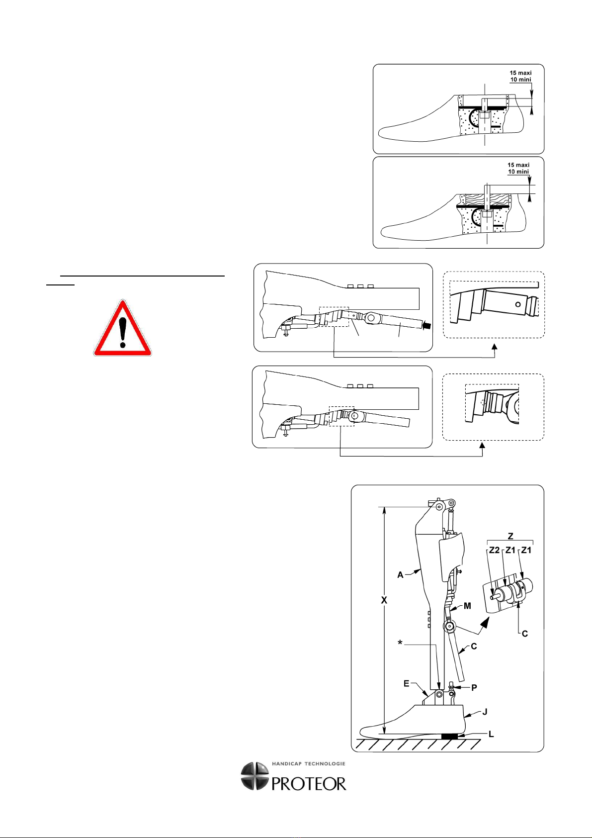
V : VERIFICATIONS: (Fig.12)
a/ Après installation de l'emboîture, vérifier qu'en flexion cette emboîture vienne toucher
l'arceau A1 du châssis avant que le bloc hydraulique B ne vienne toucher le bord interne
A2 du châssis.
b/ Les têtes taraudées Z1 seront en appui sur les bords du châssis A.
c/ Serrer le contre-écrou V.
d/ Démonter l'outil d'immobilisation en rotation Z.
VI : REGLAGES (Fig. 13, 14 et 15)
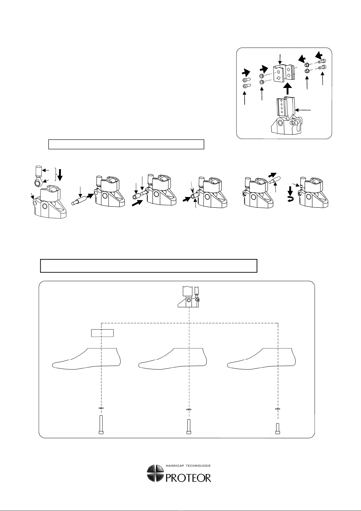
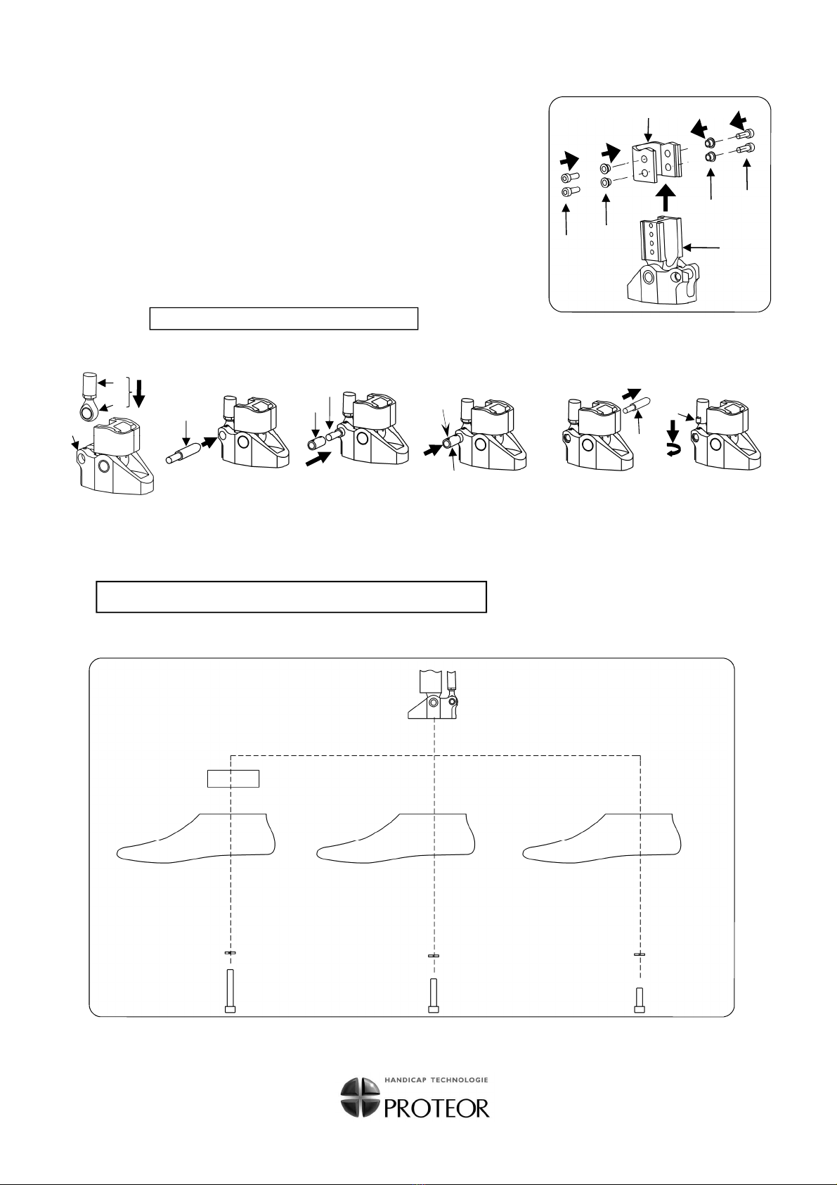
Mise à l'aplomb de l'unité hydra-cadence
a/ Maintenir l'unité hydra-cadence dans une position verticale
et marquer au crayon en avant du centre articulaire de la
cheville un repère situé à 12 mm. (fig.13)
b/ Utiliser le bouton B4 de réglage de hauteur du talon pour
modifier l'emplacement du centre articulaire de genou
(fig.15).
Le centre articulaire de genou doit passer par une ligne verticale
venant se situer au repère antérieur de 12 mm en avant de
l'articulation de cheville (fig.13)..
c/ La prothèse étant toujours placée sur une surface horizontale,
vérifier à l'aide d'un niveau que la face supérieure soit
parfaitement horizontale. Si nécessaire, modifier le réglage
par le piston de genou B1 (fig.14)
Pour ce faire :
- Desserrer l'écrou B2.
- Faire tourner le piston B1 en utilisant les clés spéciales
références 5F01 et 5F04.
- Le réglage désiré étant obtenu, resserrer l'écrou B2.
IMPORTANT
:
Après ce réglage, à l'aide d'une petite pierre à affûter,
supprimer la bavure sur les petits trous situés au niveau
supérieur de la tige de piston B1.
d/ Réglage de la cadence (fig.14).
Pour régler la vitesse de la cadence, agir sur le
bouton à base rouge B3.
Fermer complètement en tournant dans le sens des
aiguilles d'une montre, puis ouvrir en tournant la clé
de 3 tours 1/2 ou 7 demi-tours. Ne jamais aller au-
delà de cette limite sous peine de détériorer le joint
de caoutchouc.
Le réglage se fera dans cette limite, ce qui aura pour but de
réduire ou d'augmenter le passage du fluide, provoquant
une résistance ou non.
e/ Réglage de la hauteur de talon (fig.15)
Pour modifier la hauteur de talon sans changer l'aplomb de
la prothèse (exemple : changement de chaussure), agir sur
le bouton vert B4 .
1P5099-R-1113 6/21
Fig. 13
Fig. 15
B4
B2
Fig. 14
B3
B1
CORRECT
A1
A2
B
INCORRECT
!
!
!
!
Fig. 12
Z
(Z1/Z2)
B2
B1
A1
B
V
B3

ASSEMBLY AND ADJUSTMENT INSTRUCTIONS FOR 1P50 - R
CONNECTION WITH OTHER PROSTHETIC MODULES :
Connection in upper part with any Proteor standard module for knee linking, and in lower part with any SACH or DYNASTEP foot
from PROTEOR range.
USE :
For patients up to 100 kg, and for any activity level.
I : PACK CONTENTS (Fig.1)
A Carbon frame
B Hydraulic unit
C Rod
D Upper joint
E Lower joint
F Hexagonal hollow screw
with cylindrical head (x 4)
G Spacers (x 4)
G1 Plain washer
G2 Spring Grower
H1 Hexagonal hollow screw
with cylindrical head
M10x30
H2 Hexagonal hollow screw
with cylindrical head
M10x45
H3 Hexagonal hollow screw
with cylindrical head
M10x60
KToll for rod reinstallation
Z
Tool for locking in rotation
CAUTION :
1) When cutting and assembling, never modify the position of the green knob of the hydraulic unit.
2) The cutting block ref. 1 P 5070 must IMPERATIVELY be used for adjusting the length of the frame and that
of the rod. PROTEOR cannot be held liable if the Hydracadence frame is incorrectly cut.
3) The hydraulic unit is sealed up. Removing the seal voids the warranty (do not dismantle or lubricate).
II : CHECK THE SCREW FITTINGS FOR THE FOOT
Feet references 1A111, 1A112, 1A118, 1A128 and 1A21 : (Fig.2)
- Spring Grower G2
-Screw H2 (M10x45)
1P5099-R-1113 7/21
Fig. 2
Fig. 1
E
K
PROTEOR S A
6 rue de la Redoute - 21850 Saint-Apollinaire - France
Tél. 33 (0) 3 80 78 42 10 - Fax 33 (0) 3 80 78 42 15
ht.orthopedie@proteor.com - www.proteor.com

a) - Fit the prosthesis to measure dimension X (fig.5c)
X = knee joint / heel
As indicated in figure 5, fit the following parts :
A Complete frame with hydraulic unit
C Rod (not connected with the eyelet P)
E Lower joint
J Foot
- Be care that the lower part of the frame be stopped by
the lower joint (see the contact point indicated by
*
on fig.5).
- Fit tool Z for locking in rotation.
Z2 threaded shank will get through the C rod head axis hole.
- Place under the heel a wedge L corresponding to the
height of the shoes instep usually worn by the patient.
- Keep the assembly vertical and measure distance XX as indicated in
fig.5.
Feet reference 1A101 : (Fig.3)
- Spring grower G2
- Screw H1 (M10x30)
Dynastep Foot 1A101 when fitted with the frame been sawn to the length
relevant to feet 1A21 or 1A118 : (Fig.4)
- Spring grower G2
- Screw H3 (M10x60)
- Wooden group 1D70/1D71
III : LENGTH ADJUSTMENT OF THE FRAME
AND THE ROD
CAUTION :Check when fitting that the piston M
is in the neutral position. To make sure, press
the end of rod C with your thumb to move back
piston M (Fig.5a), then release the pressure to
allow piston M to return to the neutral position
(Fig.5b)
1P5099-R-1113 8/21
Fig. 4
Fig. 3
Fig. 5c
M C
Fig. 5a
Fig. 5b

- Use a hacksaw with a blade for cutting steel to cut rod C (Fig.6) along surface Sof the cutting block (fig.6), then cut frame Aalong surface
Tof the cutting block.
- With a ø 7 mm drill, bore 4 connection holes using the guide holes R of the cutting block (Fig.6).
- Remove the { frame A / hydraulic unit B / rod C} assembly from the cutting block and burrs.
IV : ASSEMBLING
a) - Fitting the ankle joint
Detach the eyelet from the joint assembly (Fig.7)
- Undo screw N
- Drive out pin O
- Remove eyelet P
Fit the eyelet to the rear rod (Fig.8)
CAUTION! : Keep in place the tool for locking in rotation.
- Screw
- Do not tighten lock nut V.
b) - Calculating length Y to be cut (Fig.5b)
Measure on the patient his knee/ground distance.
This measurement must be made without shoes. For the knee, the measure will be considered as beginning at the physiological
joint axis.
KNEE / GROUND MEASURED ON A PATIENT = W
- Calculate length Y to be cut
This value is the result of the following formula : Y = X - W + 4mm
c) - Frame and rod cutting, connection holes (Fig.6)
CAUTION ! : Do not adjust the green knob of the hydraulic unit. Keep in place the tool for locking in rotation.
-Fit the {frame A / hydraulic unit B/ rod C}assembly in the cutting block as shown in Fig.6, taking care to adjust distance Y.
-Tighten the frame and rod locking screws.
1P5099-R-1113 9/21
V
Frame
A
Rear rod C
Fig. 8
O
N
P
Fig. 7
Fig. 6
A
Bench-vice
Cutting block
1P5070
B Z C
Y
T
S
R

1P5099-R-1113 10/21
b) - Feet assembling (Fig.11)
CAUTION : Do not tighten the eyelet lock nut yet. Keep tool Z in place.
G F
2
1
3
23
F G E
A
Fig. 9
Advised thightening
torque value : 22 Nm
Fig. 11
1D70
1D71
1A101 1A101
1A111 1A112
1A118 1A128
1A21
G2
G2
G2
M10x30
(H1)
M10x45
(H2)
M10x60
(H3)
Fit the ankle joint onto the frame (Fig.9)
1) Slide joint E into frame A
2) Position spacers Gin the frame holes
3) Thighten screws F after having coated them with average strength adhesive ref.XC047.
Advised thightening torque value : 11 Nm
Fit the rod and the ankle joint together (Fig.10 a/b/c/d/e/f)
1) Fit the {rod C / eyelet P} assembly into the rear shackle of joint E (fig.10a)
2) Use tool Kto line up boring of joint Ewith that of eyelet P(fig.10b)
3) Slip pin Oon the part of tool Kwith small diameter (fig.10c)
4) Push pin Oto fit it and make sure that one of the holes * is lined up with the tapped hole of
joint E (fig.10d)
5) Remove tool K(fig.10e)
6) Tighten screw Nafter having coated it with average strength adhesive ref. XC047 (fig.10f).
CAUTION :Do not tighten the eyelet lock nut yet.
E
C
P
Fig. 10a
K
Fig. 10b Fig. 10c
O K
O
*
Fig. 10d
K
Fig. 10e
N
Fig. 10f

1P5099-R-1113 11/21
V : CHECKING (See fig.12)
a) After fitting the socket, check that in flexion this socket comes into contact with hoop A1 of
the frame before the hydraulic unit B comes up against the inside A2 of the frame.
b) Z1 tapped heads will be supported by frame A edges.
c) Tighten the lock nut V.
d) Dismantel tool Z for locking in rotation.
VI ADJUSTMENT (fig.13, 14 and 15)
Getting the perpendicularity of the hydracadence unit.
a) Keep the hydracadence unit vertical and make a mark with
a pencil at 12 mm in front of the articular center of the ankle
(fig.13).
b) Use the heel height adjustment knob B4 to modify the
place of the articular center of the knee (fig.15).
The articular center of the knee must be on the vertical line
crossing at the mark situated 12 mm in front of the ankle joint. (fig.13).
c) The prosthesis being still on an horizontal area, check with a level
that the upper face is perfectly horizontal. If necessary, modify the
adjustment with the knee piston B1 (fig.14).
To do so :
- Loosen nut B2.
- Turn piston B1 with the special wrenches reference
5F01 and 5F04.
- When adjusted as required, retighten nut B2.
IMPORTANT
After this adjustment, remove the smear on the small holes
located at the upper level of piston rod B1.
d) Pace adjustment (Fig.14)
To adjust the pace, use the red based knob B3.
Turn clockwise to lock completely, then give 3 and a half wrench
turns or 7 half-turns to open. Never exceed this limit because it
could damage the rubber gasket.
This is the limits of the adjustment. This adjustment will decrease
or increase the entry of the fluid, creating resistance or not.
e) Heel height adjustment (Fig.15)
To change the height of the heel without altering the
perpendicular setting of the prosthesis (e.g. change of footwear),
use the green knob B4.
Fig. 13
B2
Fig. 14
B3
B1
Fig. 15
B4
Fig. 12
B2
B1
A1
B
B3
Z
(Z1/Z2)
V
GOOD
A1
A2
B
WRONG
!
!
!
!

ZUSAMMENBAU- UND JUSTIERANLEITUNG FÜR 1P50 - R
VERBINDUNG MIT ANDEREN PROTHESENMODULE :
Für den oberen Teil mit jedem von Proteor genormten Knieverbindung und für den Unterteil S.A.C.H. oder DYNASTEP Fuß von
PROTEOR.
VERWENDUNG :
Patienten bis zu 100 kg ; jede Aktivität.
I : INHALT DER VERPACKUNG (Abb.1)
AKarbonrahmen
BHydraulische Einheit
CPleuelstange
DKniegelenk
EKnöchelgelenk
FSechskantschrauben mit
zylindrischem Kopf (x 4)
GQuerstücke (x 4)
G1 Unterlegscheibe
G2 Federring
H1 Sechskantschrauben
mit zylindrischem Kopf
M10x30
H2 Sechskantschrauben
mit zylindrischem Kopf
M10x45
H3 Sechskantschrauben
mit zylindrischem Kopf
M10x60
KWerkzeug zum Wiedereinsetzen der
Pleuelstange
Z Werkzeug zur Rotationsfestsetzung
WICHTIG :
1) Beim Schneiden und Zusammenbauen, die Lage des grünen Knopfs der hydraulischen Einheit nie ändern.
2) Es ist unbedingt nötig den Schnittblock 1P5070 zu verwenden, um die Länge des Rahmens und der
Pleuelstange zu bestimmen. Proteor ist nicht verantwortlich in Falle eines falschen Schnitts des Rahmens.
3) Die Hydraulische Einheit ist versiegelt. Die Garantie erlischt, wenn das Siegel entfernt ist (bitte nicht
zerlegen oder schmieren).
II : ÜBERPRÜFUNG DER FUßVERSCHRAUBUNG
Füße 1A111, 1A112, 1A118, 1A128 und 1A21 : (Abb.2)
- Federring G2
- Schraube H2 (M10x45)
1P5099-R-1113 12/21
Abb. 2
Abb. 1
E
K
PROTEOR S A
6 rue de la Redoute - 21850 Saint-Apollinaire - France
Tél. 33 (0) 3 80 78 42 10 - Fax 33 (0) 3 80 78 42 15
ht.orthopedie@proteor.com - www.proteor.com

a) - Die Prothese zusammenbauen um die Höhe X zu messen
(Kniegelenk/Ferse). (Abb.5c)
- Die folgenden Teile, wie gezeigt nebenstehend, zusammenbauen :
A Kompletter Rahmen mit der hydraulischen Einheit
C Pleuelstange (mit der Öse Pnicht verbunden)
E Knöchelgelenk
J Fuß
- Achtung : der untere Teil des Rahmens muß gegen das untere Gelenk
angehalten sein (Sehen Sie den Berührungspunkt
*
nebenstehend).
- Das Werkzeug Z zur Rotationsfestsetzung einsetzen. Die Gewindestiel Z2
in dem Loch der Achse des Pleuelkopfs setzen.
- Unter der Ferse einen Absatz L setzen, die der Absatzhöhe des Schuhes
des Patienten entspricht.
- Von Mitte Kniedrehpunkt bis Boden die Höhe X ermitteln. Dabei sollte der
Prothesenaufbau lotgerecht erfolgen.
Füße 1A101 : (Abb.3)
- Federring G2
- Schraube H1 (M10x30)
Fuß Dynastep 1A101, montiert mit einem Rahmen, der an der Länge für Fuß 1A21
oder 1A118 abgesägt ist : (Abb.4)
- Federring G2
- Schraube H3 (M10x60)
- Fußbefestigungsblock 1D70/1D71
III : BESTIMMUNG DER LÄNGE DES RAHMENS
UND DER PLEUELSTANGE
ACHTUNG Beim Einsetzen sollen Sie über-
prüfen, daß der Kolben M in der neutralen Lage
ist. Zu diesem Ziel, einen starken Druck auf das
Ende der Pleuelstange C mit dem Daumen
ausüben um den Kolben M zurückzusetzen
(Abb.5a). Dann den Druck entspannen und den
Kolben indie neutrale Lage zurückkommen
lassen (Abb.5b)
1P5099-R-1113 13/21
Abb. 3
Abb. 4
Abb. 5c
M C
Abb. 5a
Abb. 5b

- Mit der Metallsäge die Pleuelstange C längs der Oberfläche S des Schnittblocks absägen (Abb. 6). Dann den Rahmen A längs der Ober-
fläche T des Schnittblocks absägen
- Mit einem 7 mm Ø Bohrer und gemäß der Zeichenlöcher R des Schnittblocks, die 4 Verbindungslöcher bohren (Abb. 6).
- Die zusammengesetzten Rahmen A / hydraulische Einheit B / Pleuelstange Caus dem Schnittblock nehmen und entgraten.
IV : ZUSAMMENBAU
a) - Zusammenbau des Knöchelgelenkes
Die Öse aus der Gelenkskonstruktion ausbauen (Abb.7)
- die Schraube Nherausdrehen
- die Achse Oaustreiben
- die Öse Pabnehmen
Die Öse auf der hinteren Pleuelstange einsetzen. (Abb.8)
ACHTUNG ! : Das Werkzeug zur Rotationsfestsetzung im Platz halten.
- anschrauben
- die Gegenmutter V nicht hineindrehen.
b) - Bestimmung der zu schneidenden Länge Y (Abb.5b)
- Das Knie-Boden-Maß beim Amputierten ohne Schuhe ermitteln.
KNIE - BODEN - MAß = W
Rechnung der zu schneidenden Länge Y : Y = X - W + 4mm
c) - Schnitt des Rahmens und der Pleuelstange. Durchführung der Verbindungslöcher. (Abb.6)
ACHTUNG ! Die Einstellung des grünen Knopfes der hydraulischen Einheit nicht ändern. Das Werkzeug zur Rotations-
festsetzung im Platz halten.
- Das Maß Y mit Sorgfalt ermitteln und die zusammengesetzten Rahmen A / hydraulische Einheit B / Pleuelstange Cin den Schnittblock
einsetzen (wie gezeigt in Abbildung 6).
- Die Festsetzungsschrauben des Rahmens und der Pleuelstange anziehen.
1P5099-R-1113 14/21
O
N
P
Abb. 7
Abb. 8
V
Rahmen
A
Hintere Pleuestange
C
Abb. 6
A
Klemme
Schnittblock
1P5070
B Z C
Y
T
S
R

1P5099-R-1113 15/21
Das Knöchelgelenk auf dem Rahmen einsetzen (Abb.9)
1) Das Gelenk E in dem Rahmen A schieben.
2) Die Querstücke G in die Rahmenlöcher einsetzen
3) Die Schraube F mit mittel starkem Klebstoff (ref. XC047) überstreichen und dann
hineindrehen.
Empfohlenes Drehmoment : 11 Nm
Die Pleuelstange und das Knöchelgelenk befestigen (Abb.10 a/b/c/d/e/f))
1) Die zusammengesetzten Pleuelstange C und Öse Pin die hintere Aufnahme Edes
Gelenkes einsetzen (Abb.10a)
2) Das Werkzeug Kverwenden, um das Gewindeloch des Gelenkes Edem
Gewindeloch der Öse P anzupassen (Abb.10b)
3) Die Achse O auf dem Teil des Werkzeugs K mit kleinem Durchmesser aufziehen
(Abb.10c)
4) Die Achse O schieben, um sie einzusetzen. Dabei muss ein der Löcher* dem
Gewindeloch des Gelenkes E entsprechen (Abb.10d)
5) Das Werkzeug Kabnehmen (Abb.10e)
6) Die Schraube N mit mittel starkem Klebstoff (ref. XC047) überstreichen, und dann
hineindrehen (Abb.10f).
b) - Zusammenbau des Fußes (Abb.11)
ACHTUNG : Die Gegenmutter der Öse noch nicht hineindrehen. Das Werkzeug Z im Platz halten.
G F
2
1
3
23
F G E
A
Abb. 9
Abb. 11
Empfohlenes
Drehmoment : 22 Nm
1D70
1D71
1A101 1A101
1A111 1A112
1A118 1A128
1A21
G2
G2
G2
M10x30
(H1)
M10x45
(H2)
M10x60
(H3)
ACHTUNG : Die Gegenmutter der Öse noch nicht hineindrehen.
E
C
P
Abb. 10a
K
Abb. 10b Abb. 10c
O K
O
*
Abb. 10d
K
Abb. 10e
N
Abb. 10f

1P5099-R-1113 16/21
V : ÜBERPRÜFUNGEN (Abb.12)
a) Den Prothesenschaft adaptieren. Der Schaft muß in Beugestellung das Teil A1 berühren, bevor
die hydraulische Einheit B den inneren Rand A2 des Rahmens berührt.
b) Die Gewindeköpfe Z1 stützen sich auf den Rahmenränder A
c) Die Gegenmutter V hineindrehen.
d) Das Werkzeug zur Rotationsfeststellung Z entnehmen.
VI : EINSTELLUNGEN (Abb.13, 14 und 15)
Die hydraulische Schwungphasenstreuerung einstellen.
a/ 12mm vor dem Knöchelgelenkzentrum mit einem Bleistift eine
Markierung setzen (Abb.13).
b/ Mit dem Absatzhöhen-Einstellknopf B4 kann die Lage des
Kniegelenkzentrums verändert werden.(Abb.15).
Das Kniegelenkzentrum muß sich in der Lotlinie befinden,
welche 12 mm vor dem Knöchelgelenk liegt. (Abb.13)
c) Die Prothese muß auf einer planen Fläche stehen. Das
Kniepaßteil muß völlig waagrecht stehen. Wenn nötig, die
Einstellung mit dem Kniekolben B1 ändern (Abb.14).
Zu diesem Ziel :
- die Mutter B2 herausdrehen
- den Kolben B1 mit dem Fachschlüssel 5F01 und 5F04 drehen.
- wenn die gewünschte Einstellung erreicht ist, die Mutter
B2 hineindrehen.
WICHTIG :
Nach dieser Einstellung, den Grat auf den kleinen
Löcher des oberen Teils der Kolbenstange B1 mit
einem kleinen Schleifwerkzeug entfernen.
d) Einstellung der Schwungphase (Abb.14)
Mit dem roten Justierknopf B3 wird die Schwungphase
eingestellt. Im Uhrzeigersinn wird die Hydraulik völlig zugedreht.
Mit 3 1/2 Schlüsseldrehungen die Hydraulik öffnen.
Die Umdrehungen nicht überschreiten, sonst könnten die
Dichtungen beschädigt werden.
Der Widerstand wird über diesen Knopf eingestellt.
Das ist die Einstellungsgrenze. Diese Einstellung wird den
Durchzug der Flüssigkeit vermindern oder vergrößern, und
das wird einen Widerstand schaffen.
e) Einstellung der Absatzhöhe (Abb.15)
Über den grünen Justierknopf B4 wird die Absatzhöhe
eingestellt. Die Aufbaurichtlinie wird dabei nicht beeinflußt.
Abb. 13
B2
Abb. 14
B3
B1
Abb. 15
B4
Abb. 12
Z
(Z1/Z2)
B2
B1
A1
B
B3
V
RICHTIG
A1
A2
B
FALSCH
!
!
!
!

INSTRUCCIONES DE MONTAJE Y DE UTILIZACION PARA 1P50 - R
CONEXIONES :
Esta rodilla admite en su parte superior los dispositivos de conexión PROTEOR de rodilla (1K03, 1K30, 1K160…) y en su parte
inferior los pies de tipo SACH y DYNASTEP de la línea PROTEOR
USO :
Se destina a pacientes cuyo peso carga incluida no exceda 100 kg
IMPORTANTE :
1) Durante las operaciones montaje no modificar la posición del botón verde del cilindro hidráulico.
2) La utilización del Bloque de corte ref. 1P5070 es INDISPENSABLE para la adaptación personalizada de la
estructura y de la biela. PROTEOR rechaza toda responsabilidad en caso de un corte incorrecto de la
estructura.
3) El cilindro hidráulico esta sellado. Romper el sello anula la garantía del producto (no desensamblar ni
lubricar).
II : UTILIZACION DE LOS TORNILLOS PARA CADA TIPO DE PIE
Pies 1A111, 1A112, 1A118, 1A128 et 1A21 : (Dib.2)
- Arandela Grower G2
- Tornillo H2 (M10x45)
I : CONTENIDO (Dib.1)
A Estructura de carbono
B Cilindro hidráulico
C Biela
D Articulación superior
E Articulación inferior
F Tornillos cabeza cilíndrica
hexágono interior (x 4)
G Riostras (x 4)
G1 Arandela llana
G2 Arandela Grower
H1 Tornillo cabeza cilíndrica
hexágono interior (x 4)
M10x30
H2 Tornillo cabeza cilíndrica
hexágono interior (x 4)
M10x45
H3 Tornillo cabeza cilíndrica
hexágono interior (x 4)
M10x60
K Herramienta para montaje de biela
Z Herramienta de bloqueo de la rotación
1P5099-R-1113 17/21
Dib. 2
Dib.1
E
K
Instalar la tuerca con la
parte cónica hacia la
varilla roscada
Instalar la tuerca con la
parte cónica hacia
abajo
PROTEOR S A
6 rue de la Redoute - 21850 Saint-Apollinaire - France
Tél. 33 (0) 3 80 78 42 10 - Fax 33 (0) 3 80 78 42 15
ht.orthopedie@proteor.com - www.proteor.com

a) - Tomar la medida X (Dib.5c)
MEDIDA DEL MONTAJE NUEVO (articulación superior - talón) = X
Realice como lo indica el dibujo 5, un montaje sin ajustar las piezas :
A Estructura con cilindro hidráulico
C Biela (separada del ojete P)
E Articulación inferior
J Pie
- Observe que la parte baja de la estructura esté en contacto con la articulación
inferior (
*
en Dib.5c)
- Instale la herramienta de bloqueo de la rotación Z. La varilla roscada Z2 atra-
viesa el agujero del eje de articulación de la biela C
- Realce el pie según la altura del zapato de su paciente L
- Mantenga el conjunto verticalmente y tome la medida X
Pie 1A101 : (Dib.3)
- Arandela Grower G2
- Tornillo H1 (M10x30)
Pie Dynastep 1A101 en el caso de une estructura que ha sido previa-
mente cortada para utilización con pie 1A21 ó 1A118 : (Dib.4)
- Arandela Grower G2
- Tornillo H3 (M10x60)
- Compensación de madera de 1D70/1D71
III : ADAPTACION DE LA ESTRUCTURA Y DE LA
BIELA
PRECAUCION : Verifique que el pistón M se en-
cuentra en posición neutra. Para esto, ejercer con
el pulgar una fuerte presión en la extremidad de
la biela C con el fin de hacer retroceder el pistón
M (Dib.5a) , y después liberar la presión para que
el pistón regrese a su posición neutra (Dib.5b)
1P5099-R-1113 18/21
Dib. 5c
Dib. 4
Dib. 3
M C
Dib. 5a
Dib. 5b

1P5099-R-1113 19/21
- Con una sierra de mano para corte de metales equipada con hoja para acero, corte la biela C tomando apoyo en la superficie S del Bloque
de corte (Dib. 6). Después corte la estructura A tomando apoyo en la superficie T del Bloque de corte. (Dib.6).
- Con una broca de ø 7 mm, taladre los 4 agujeros de unión a través de los agujeros guias R del Bloque de corte.
- Retire el conjunto A/ B/ Cdel Bloque de corte y retire las rebabas.
IV : MONTAJE
a) - Instalación de la articulación de tobillo
Separar el ojete del conjunto de la articulación (Dib.7)
- Desatornillar N
- Sacar de su alojamiento el eje O
- Retirar el ojete P
Atornillar el ojete en la biela posterior C sin ajustar la contratuerca V (Dib.8)
PRECAUCION ! Mantenga la instalación de la herramienta de bloqueo de la rotación.
b) - Determinar el corte de la estructura Y (Dib.5b)
MEDIDA DE REFERENCIA DEL PACIENTE (rodilla - talón) = W
- Mida sobre el paciente la distancia rodilla - suelo.
Esta medida debe realizarse del lado opuesto al de la amputación, con el pie descalzo.
Como origen de la medida se tomará en consideración el eje articular fisiológico de la rodilla.
- Para el corte utilise la formula siguiente : Y =X - W + 4mm
c) - Corte de la estructura, de la biela, y realización de los agujeros de unión (Dib.6)
PRECAUCION !: No modificar el ajuste del botón verde del cilindro hidraúlico.
Mantenga la instalacion de la herramienta de bloqueo de la rotación.
- Instale el conjunto estructura A / cilindro hidráulico B / biela C en el Bloque de corte 1P5070 (no incluido) como indicado en el dibujo 6,
verificando cuidadosamente la longitud del corte Y. Ajuste los tornillos de inmovilización de la estructura y de la biela.
O
N
P
Dib. 7
Dib. 8
V
Estructura
A
Biela posterior
C
Bloque de corte
1P5070 Tornillo de banco
Dib. 6
A
B Z C
Y
T
S
R
Bloque de corte
1P5070

1P5099-R-1113 20/21
b) - Ensamble del pie (Dib.11)
PRECAUCION : Aun no debe ajustar la contratuerca del ojete.
Mantenga la instalación de la herramienta de bloqueo de la rotación.
Ensamble la articulación inferior con la estructura (Dib.9)
1) Insertar la articulación E en la estructura A
2) Colocar las riostras G en los agujeros de la estructura
3) Atornillar los tornillos F después de haberles aplicado pegamento (ref. XC047).
Par de ajuste recomendado : 11 Nm
Solidarice la biela y la articulación inferior (Dib.10 a/b/c/d/e/f)
1) Introduzca el conjunto C / P en la parte trasera de la articulación E (Dib.10a)
2) Utilice la herramienta K para alinear los ejes de Ey de P(Dib.10b)
3) Inserte el eje Opor el lado angosto de K (Dib.10c)
4) Empuje Ocompletamente en la parte trasera de Everificando que uno de sus agujeros
coincida con el agujero roscado de E(Dib.10d)
5) Retire la herramienta K (Dib.10e)
6) Atornille N después de haberle aplicado pegamento (ref. XC047). (Dib.10f)
G F
2
1
3
23
F G E
A
Dib 9
Dib. 11
Par de ajuste reco-
mendado : 22Nm
1D70
1D71
1A101 1A101
1A111 1A112
1A118 1A128
1A21
G2
G2
G2
M10x30
(H1)
M10x45
(H2)
M10x60
(H3)
PRECAUCION : Aun no debe ajustar la contratuerca del ojete.
E
C
P
Dib. 10a
K
Dib. 10b Dib. 10c
O K
O
*
Dib. 10d
K
Dib. 10e
N
Dib. 10f
Table of contents
Languages:
Other PROTEOR Mobility Aid manuals