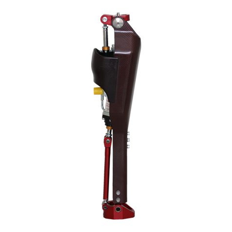
PROTEOR PROFESSIONAL EASY RIDE User manual

EASY RIDE
1P650
PROFESSIONAL
FR Notice d’Utilisation
EN Instruction for use
DE Gebrauchsanweisung
IT Istruzioni per l’uso
ES Instrucciones de uso
T Instruções de utilização
NL Gebruikershandleiding
DA Brugervejledning
NO Brukerveiledning
SV Bruksanvisning
FI Käyttöohjeet
L Instrukcja użytkowania
CS Návod k použití
SK Návod na používanie
HR Upute za uporabu
RU Инструкция по использованию
UK Інструкція з використання
JA 取扱説明書
ZH 使用说明
1
650
99
-
0421

Il est important de lire et d’expliquer la notice destinée au patient en sa présence.
1. ELEMENTS INCLUS
Dési nation Référence Inclus / Vendu séparément
Genou 1P650 Inclus
Pompe à air 1P65012 Inclus
Vis M6x14 (x2) WMBT6014 Inclus
Clé Torx T30 (x2) WKT030 Inclus
Outil de changement d’axe 1P65019 Inclus
Pyramides femelles 1K185 et 1K66 Vendu séparément
Kit d’habillage 1P653 Vendu séparément
2. DESCRIPTION, PROPRIETES ET MECANISME D’ACTION
A. Description
Genou mono-axial multisport à fort impact équipé d’un amortisseur air/huile nouvelle génération et de ses deux connecteurs dont le
supérieur est rotatif.
En fonction de l’activité choisie, le porteur peut modifier facilement la position du genou et ses réglages : GLISSE ou VELO
Il est constitué de deux pyramides mâles en pièces de liaison supérieure et inférieure. Ces pyramides sont destinées à recevoir une
pyramide femelle. Il est possible de remplacer les pyramides mâles fournies pas des pyramides femelles à commander séparément.
B. Propriétés
Référence 1P650
Poids 1200 g
Position GLISSE VELO
Pré-flexion 12° 0°
Flexion maximale 50° 130°
Poids maximum Patient
(Port de char e inclus) 125 kg
Position GLISSE Position VELO
Ce dispositif a été testé dans les conditions de la norme NF EN ISO 10328 pour un niveau de charge P6 (soit 125Kg), pendant 1 million
de cycles. La durée de vie est dépendante de l’activité et de l’utilisation du patient.
3. DESTINATION/INDICATIONS
Ce dispositif médical est fourni aux professionnels de santé (orthoprothésiste) qui formeront le patient à son utilisation. La prescription est
faite par un médecin avec l’orthoprothésiste, qui jugent de l’aptitude du patient à l’utiliser.
Ce dispositif est à usage sur PATIENT UNIQUE. Il ne doit pas être réutilisé sur un autre patient.
EASY RIDE – 1P650
Notice d’utilisation Orthoprothésiste
Lire avant toute utilisation
1P65099
2021-04
2
0
1
6
Hauteur totale : 257 mm
Hauteur de construction : 227
38mm
Hauteur totale :
260
mm
Hauteur de construction : 230 mm

NOTICE D’UTILISATION Page 2 sur 7
Ce dispositif est uniquement destiné à l’appareillage prothétique d’une personne amputée adapté au sport.
Il est préconisé spécifiquement pour des patients très actifs (L4) permettant la pratique de sports tels que le
surf, le snowboard, le vélo, le VTT, le roller, le skate, le paddle.
Ce dispositif n'est pas destiné à la marche.
Poids maximum (port de charge inclus) : 125 kg
Non adapté pour les enfants.
4. BENEFICES CLINIQUES
Le dispositif permet :
•La pratique de nombreuses activités sportives tant estivales (Vélo de route, skateboard, Surf) qu’hivernales (Snowboard)
•Le réglage du niveau d’amortissement en flexion et en extension
•Le réglage de la résistance à la flexion et de la force de rappel en extension par gonflage du système pneumatique
•Une adaptation à différents sports par un changement de position de l’axe de fixation de l’amortisseur.
5. ACCESSOIRES ET COMPATIBILITES
Référence 1P650
Liaison supérieure
Ancre
1K179+1K183
1K173 ou 1K176
1K177 (poids maxi 100Kg)
Connecteurs 1K172 ou 1K207-HD
Liaison inférieure Tube et
connecteur
1G01-HD+1D41HD
1D52-P6
6. MONTAGE ET MISE EN PLACE SUR LE PATIENT
A. Ali nements
Préparation :
Tracer les lignes de charge et du centre articulaire du genou (patient debout, genou
en extension complète).
Position lisse :
Plan Sa ittal :
Monter l’emboîture en flexion afin que la ligne de charge passe par le centre
articulaire de la hanche, à 3 cm environ (dépendant de l’activité) en arrière de l’axe
antérosupérieur du genou et au niveau de l’articulation métatarso-phalangienne du
pied.
Le talon peut décoller du sol.
Plan Frontal :
Monter le genou dans le prolongement de l’emboîture.
Monter le segment jambier en adduction par rapport au genou, en respectant un
angle de 10° environ (dépendant de l’activité).
La ligne de charge passe par le centre articulaire de l’emboîture et au bord médial
du pied (dépendant de l’activité).
Grand
Trochanter
Axe du
tube
Plan
sa ittal
Plan
frontal
Ligne de
charge

NOTICE D’UTILISATION Page 3 sur 7
Position vélo :
Plan Sa ittal :
Monter le genou dans le même axe que l’emboîture.
La ligne de charge doit passer par le centre articulaire de la hanche, le centre de
l’emboîture et à l’arrière de l’axe de rotation du genou.
Elle arrive environ au tiers du pied (suivre les préconisations d’alignement du pied).
Plan Frontal :
Monter le genou dans le même axe que l’emboîture.
La ligne de charge passe par le centre du genou et le centre du pied.
Une rotation interne du segment jambier peut être nécessaire.
Nota : Ces préconisations sont celles issues de tests et d’essais réalisés en laboratoire. Lors de la
mise en situation du patient dans son activité sportive, la modification de ces alignements
théoriques est tout à fait possible à condition de bien respecter les règles de sécurité et les règles
de bon usage du montage de ce type de matériel. Il en va de la sécurité et du confort du patient.
B. Chan ement de position
Le passage de la position GLISSE à la position VELO s’effectue en modifiant l’emplacement de l’axe haut du vérin de la position 1 à la
position 2 de la manière suivante :
•Dévisser les deux vis de part et d’autre de l’axe à l’aide des deux clés Torx T30 fournies.
•Sortir l’axe de son emplacement à l’aide de l’outil de changement d’axe fourni.
•Insérer l’axe dans la position désirée.
•Remettre en place les deux vis avec leurs rondelles et une goutte de frein filet faible XC048, puis les serrer au couple de
6Nm.
Le serrage et le desserrage des vis doit se faire avec une clé dynamométrique munie d’un embout Torx T30.
En cas de déformation de l’empreinte sur la tête de vis, remplacer la vis par une des deux vis fournies.
Les butées de flexion maximum en position VELO sont uniquement présentes pour protéger le vérin, elles ne doivent en aucun cas
être soumises à des contraintes de manière régulière et répétée.
C. Choix de la position et ré la es en fonction de l’activité
Le vérin fourni possède trois commandes de réglage :
•Commande BLEUE (FIRM / MEDIUM /OPEN), correspondant respectivement à une vitesse de compression lente, moyenne
et rapide.
•Commande NOIRE (ADJUSTING TRAIL MODE) correspondant à un réglage fin de la vitesse de compression, utilisable en mode
Position GLISSE
Extension
(Pré-flexion de 12°)
Flexion
(Amplitude de 50°)
Position VELO
Extension
(Aucune Pré-flexion)
Flexion
(Amplitude de 130°)
1
2
Grand
Trochanter
Plan
sa ittal Plan
frontal
Ligne de
charge

NOTICE D’UTILISATION Page 4 sur 7
OPEN uniquement, contient 3 positions : 1, 2 et 3 de souple à ferme.
•Commande ROUGE (REBOUND) correspondant à la vitesse du retour en extension.
D. Ré la e de la pression de l’amortisseur
A l’aide de la pompe fournie, mettre l’amortisseur à la pression désirée.
En cas d’excès de pression, faire baisser celle-ci à l’aide du bouton de purge situé sur la pompe.
Utiliser uniquement la pompe fournie ou une pompe munie d’un manomètre 20 bars et adaptée aux amortisseurs FOX.
Les combinaisons de positions ainsi que les réglages indiqués ci-dessous sont donnés à titre indicatif et sont susceptibles de varier en
fonction des activités et du poids du patient :
Activités sportives :
1. Position axe :
•VELO : vélo de route, VTT rando, VTT descente et motocross
•GLISSE : toutes autres activités
2. Ré la e de la flexion :
•OPEN (commande bleue)
3. Ré la e de l’extension :
•REBOUND au maximum en général et à adapter en fonction du besoin (commande rouge)
4. Pression :
•0 bar : Vélo de route, VTT de rando
•1 à 3 bars : Surf, paddle, ski nautique, wakeboard
•4 à 6 bars : VTT descente, snowboard, ski de piste
•5 à 10 bars : Fitness, sport de raquettes, sports de combat, moto-cross
La pression d’air de l’amortisseur ne doit jamais dépasser 20,6 bars.
Il est impératif de vider l’air de l’amortisseur lors d’un passage en haute altitude (voyage en avion…).
Remettre le capuchon sur la valve après un réglage de la pression d’air.
Déplacements entre activités / franchissement d’obstacles / besoin de sécurité :
1. Réglage de la flexion :
•FIRM (commande bleue)
7. DETECTION DES DYSFONCTIONNEMENTS
Si vous constatez un comportement anormal ou que vous sentez des modifications des caractéristiques du dispositif, ou si celui-ci a reçu
un choc important, consultez votre orthoprothésiste.
8. MISES EN GARDE, CONTRE-INDICATIONS, EFFETS SECONDAIRES
A. Mises en arde
Lors des premières utilisations du genou, il est possible que des traces d’huile apparaissent. Les essuyer à l’aide d’un chiffon
doux.
L’amortisseur, ayant subi une préparation spécifique, ne doit en aucun cas être démonté ou détourné de son utilisation.
Laisser refroidir l’amortisseur après utilisation, risque de brûlures.
En cas de changement de température important de l’amortisseur, son comportement peut varier.
L’amortisseur est livré dégonflé pour éviter tout problème lors de son transport.
Un risque de coincement de doigt ou de pincement des vêtements dans l’articulation du genou existe. Pour éviter tout risque de
blessure du fait du mouvement de l’articulation, bien veiller à ce que personne ne mette les doigts à proximité ou à l’intérieur du
mécanisme.
B. Contre-indications
Ne jamais graisser les axes du genou, cela pourrait entrainer leur détérioration rapide.
En cas de port de charge, le fonctionnement du genou peut être perturbé.
La garantie ne couvre pas les détériorations consécutives à un mauvais usage, à un alignement inadapté, à une utilisation dans un
environnement non adapté, ou toute utilisation inappropriée.
En cas de dysfonctionnement, d’usure prématurée ou de traces de rouille, consulter au plus vite votre orthoprothésiste
Ne jamais laisser ce dispositif près d’une source de chaleur : risque de brûlure et de dégagement toxique.

NOTICE D’UTILISATION Page 5 sur 7
L’utilisation de solvants est proscrite.
C. Effets secondaires
Il n’y a pas d’effets secondaires directement lié au dispositif.
Tout incident grave survenu en lien avec le dispositif doit faire l’objet d’une notification au fabricant et à l’autorité compétente de
l’Etat membre.
9. ENTRETIEN, STOCKAGE, ELIMINATION ET DUREE DE VIE
A. Entretien/ nettoya e
Vérifier régulièrement l’état des vis de butées de flexion
Vérifier régulièrement le serrage des vis M6 (couple de serrage 6Nm).
En cas de dysfonctionnement, d’usure prématurée ou de traces de rouille,
consulter au plus vite votre orthoprothésiste
Vous pouvez nettoyer le genou à l’aide d’une éponge humide
Nettoyer le genou après chaque activité « polluante » (eau, boue, utilisation en
immersion).
Après une immersion dans de l’eau de mer, procéder à un rinçage soigné à l’eau
douce, puis à un séchage complet.
Ne pas utiliser de solvant ou autres produits agressifs pour le nettoyage
Pour l’entretien de l’amortisseur, se référer aux notices du fabricant fournies avec
le genou.
B. Monta e du kit de remplacement d’habilla e
Durant le cycle de vie normale du genou de sport EASY RIDE, il est possible que certaines pièces rencontrent un vieillissement plus
rapide que d’autres suivant l’activité réalisée. PROTEOR fournit les pièces les plus exposées dans un kit d’habillage (1P653) constitué
de : •Coque droite (x1)
•Coque haute (x1)
•Coque Gauche (x1)
•Rondelles M3 (x8)
•Vis M3x8 (x8)
Le montage est réalisé selon les opérations suivantes :
1. Retirer les huit vis M3x8* à l’aide d’une clé Allen taille 2, puis décoller les trois coques (l’utilisation d’un solvant tel que de
l’acétone peut être nécessaire).
2. Nettoyer les résidus de colle sur les surfaces des flasques et de la platine haute.
3. Dégraisser les surfaces à coller à l’aide d’un solvant sec (surfaces aluminium et habillages), puis enduire l’une des deux
surfaces de colle cyanoacrylate (réf. XC053) (un filet parcourant le pourtour de la surface est généralement suffisant).
4. Coller les habillages en position et exercer une pression uniforme au moins 3 minutes
Une fois les deux surfaces en contact, ne pas effectuer de micromouvement, ne pas repositionner les pièces.
5. Mettre en place les huit rondelles avec les huit vis fournies avec du frein filet moyen XC047. Serrer au couple de 0.25Nm
Le serrage des vis doit se faire avec une clé dynamométrique munie d’un embout six pans de 2.
Après collage, le genou doit sécher au moins 24H avant utilisation.
(2x) vis de
butées de
flexion
(10x)
vis M6

NOTICE D’UTILISATION Page 6 sur 7
C. Stocka e
Température d’utilisation et de stockage : -25°C à +40°C
Humidité relative de l’air : aucune restriction
D. Elimination
Les différents éléments de ce dispositif sont des déchets spéciaux : aluminium, axes et vis en acier inoxydable, connecteurs en titane
et bagues en plastique et huile. Ils doivent être traités selon la législation en vigueur.
E. Durée de vie
Une révision du genou doit être faite toutes les 100 heures d’utilisation par votre orthoprothésiste (soit 1 an pour une activité modérée
ou 6 mois pour une activité importante).
10. DESCRIPTION DES SYMBOLES
Fabricant
Risque identifié
Marqua e CE et année de 1ère déclaration
11. INFORMATIONS REGLEMENTAIRES
Ce produit est un dispositif médical marqué CE et certifié conforme au règlement (UE) 2017/745
12. NOM ET ADRESSE DU FABRICANT
PROTEOR SAS
6 rue de la Redoute – 21850 Saint-Apollinaire – France
Tel : +33 3 80 78 42 42 – Fax : +33 3 80 78 42 15
[email protected] – www.proteor.com

NOTICE D’UTILISATION Page 7 sur 7
HISTORIQUE DES MODIFICATIONS
Version Date Rédacteur Modifications
2021-04 30/04/2021 V. Barbour Mise au format MDR

It is important to read and explain the patient information leaflet to the patient.
1. COMPONENTS INCLUDED
Designation ef. Included/Sold separately
Knee 1P650 Included
Air pump 1P65012 Included
M6x14 screw (x2) WMBT6014Z Included
T rx T30 key (x2) WKT030 Included
Pin rem ving t l 1P65019 Included
Female pyramids 1K185 and 1K66 S ld separately
C ver kit 1P653 S ld separately
2. DESC IPTION, P OPE TIES AND MECHANISM OF ACTION
A. Description
A single-axis, multi-sp rt knee that can withstand high impacts, fitted with a state- f-the-art air/ il sh ck abs rber, a distal c nnect r
and a pr ximal c nnect r that can r tate.
The wearer can easily m dify the knee p siti n and settings t adapt it t the type f activity t be perf rmed: SLIDING r BIKING
Male pyramid adapters pr vide its pr ximal and distal c nnecti n. These pyramids are designed t c nnect t a female pyramid. The
male pyramids pr vided can be replaced by female pyramids, which can be rdered separately.
B. Properties
ef. 1P650
Weight 1,200 g
Position SLIDING BIKING
Pre-flexion 12° 0°
Maximum flexion 50° 130°
Maximum patient weight
(Including carried load) 125 kg
SLIDING position BIKING position
This device has underg ne a ne-milli n-cycle test, in acc rdance with the c nditi ns described in standard NF EN ISO 10328 at a P6
l ad level (i.e. 125 kg). The service life depends n the activity perf rmed and n h w ften and h w intensively it is used by the
patient.
3. INTENDED USE S/INDICATIONS
This medical device is supplied t healthcare pr fessi nals (pr sthetists/ rth tists) wh then instruct the patient in h w t use it. The
prescripti n is drawn up by a d ct r. The d ct r w rks with a pr sthetist/ rth tist t assess whether the patient is suited t using the device.
This device sh uld be used n ONE PATIENT ONLY. It must n t be reused n ther patients.
EASY IDE – 1P650
Instructions for use for Prosthetists/Orthotists
Please read before using or working on the device
1P65099
2021-04
2
0
1
6
T tal height: 257 mm
Build height: 227 mm
38
mm
T tal height: 260 mm
Build height: 230 mm
38 mm

INSTRUCTIONS FOR USE Page 2 f 6
This device is exclusively intended t be used as pr sthetic equipment by amputees wishing t engage in
sp rts activities. It is specifically rec mmended f r very active patients (L4) and all ws them t practice
sp rts such as surfing, sn wb arding, cycling, m untain biking, r ller skating, ice skating and
paddleb arding.
This device is not intended to be used for walking.
Maximum weight (including carried l ad): 125 kg
Not suitable for children.
4. CLINICAL BENEFITS
The device all ws:
•The patient t practice many summer and winter sp rts (r ad cycling, skateb arding, surfing, sn wb arding, etc.)
•Adjustment f the degree f sh ck-abs rpti n b th in flexi n and in extensi n
•Adjustment f the resistance t flexi n and f the extensi n assist f rce (by inflating the pneumatic system)
•Cust misati n t different sp rts by changing the p siti n f the pin which secures ne end f the sh ck-abs rber.
5. ACCESSO IES AND COMPATIBILITIES
Ref. 1P650
Pr ximal adapter
Anch r
1K179+ 1K183
1K173 r 1K176
1K177 (max. weight 100 kg)
C nnect rs 1K172 r 1K207-HD
Distal adapter Tube and
c nnect r
1G01-HD+ 1D41HD
1D52-P6
6. ASSEMBLY AND FITTING TO THE PATIENT
A. Aligning
Preparation:
Mark the l ad lines and the centre f the knee j int (with the patient standing and
the knee fully extended).
Sliding position (e.g. for board sports, skiing etc.):
Sagittal plane:
M unt the knee n the s cket with slight flexi n, such that the l ad line thr ugh the
centre f the hip j int is ab ut 3 cm (depending n the activity) t the rear f the
knee's upper fr nt pin and passes thr ugh the metatars phalangeal j int f the
f t.
The heel may lift ff the gr und.
Frontal plane:
M unt the knee in line with the s cket.
M unt the leg secti n with an adducti n angle f ab ut 10° with respect t the
knee (depending n the activity).
The l ad line thr ugh the centre f the hip j int passes thr ugh the medial edge f
the f t (depending n the activity).
Greater
tr chanter
Axis f the
tube
Sagittal
plane
Frontal
plane
L ad line

INSTRUCTIONS FOR USE Page 3 f 6
Biking position:
Sagittal plane:
M unt the knee such that its axis is in line with the axis f the s cket.
The l ad line must pass thr ugh the centre f the hip j int, the centre f the s cket and
t the rear f the axis f r tati n f the knee.
The l ad line passes thr ugh the p steri r f the f t, 1/3rd f its length fr m the back
f the f t (depending n the alignment rec mmendati ns f r the f t).
Frontal plane:
M unt the knee such that its axis is in line with the axis f the s cket.
The l ad line passes thr ugh the centre f the knee and the centre f the f t.
An internal r tati n f the leg segment may be necessary.
Note: These alignment rec mmendati ns draw n the results f lab rat ry tests and trials. When
the patient is practising a sp rt, these the retical alignments can be m dified s l ng as the
setup f the device c mplies with the rules regarding safety and the rules applicable t the
c rrect use f the device n the type f equipment used. The patient's safety and c mf rt
depend n them.
B. Change of position setting
T switch between the SLIDING (f r sp rts perf rmed n a b ard, skis, skates, etc.) and BIKING p siti ns, m ve the pin that secures
the upper end f the sh ck abs rber fr m p siti n 1 t p siti n 2, as f ll ws:
•Unscrew the tw screws at the tw ends f the pin using the tw T rx T30 keys supplied.
•Rem ve the pin using the pin rem ving t l supplied.
•Insert the pin in the desired p siti n.
•Refit the tw screws with their washers, apply a dr p f XC048 l w-strength thread-l cking c mp und, and tighten the
screws t a t rque f 6 Nm.
The screws must be tightened and untightened with a t rque wrench fitted with a T rx T30 bit.
If the screw head bec mes def rmed, replace the screw with ne f the tw spares supplied.
The maximum flexi n st ps in the BIKING p siti n are nly present t pr tect the sh ck-abs rber; they must n t under any
circumstances be subjected t stresses regularly and repeatedly.
SLIDING position
Extension
(Pre-flexi n f 12°)
Flexion
(Amplitude f 50°)
BIKING position
Extension
(N Pre-flexi n)
Flexion
(Amplitude f 130°)
1
2
Greater
tr chanter
Sagittal
plane Frontal
plane
L ad line

INSTRUCTIONS FOR USE Page 4 f 6
C. Selecting the position and settings for different activities
The sh ck-abs rber fitted ffers three setting c ntr ls:
•BLUE control (FIRM / MEDIUM / OPEN) sets the c mpressi n speed t sl w, medium and fast respectively.
•BLACK control (ADJUSTING TRAIL MODE) used t fine tune the c mpressi n speed, in OPEN m de nly, with 3 p siti ns
available: 1, 2 and 3 fr m s ft t firm.
•ED control (REBOUND) sets the extensi n speed.
D. Adjusting shock-absorber pressure
Using the pump pr vided, pressurise the sh ck-abs rber t the required pressure.
If the pressure is t high, reduce it using the air release butt n n the pump.
Only used the pump supplied r a pump fitted with a 20-bar gauge suitable f r FOX sh cks.
The c mbinati ns f p siti ns and settings indicated bel w are pr vided as a guide nly and may vary as a functi n f the activities
perf rmed and the patient's weight:
Sporting activities:
1. Pin position:
•BIKING: r ad cycling, cr ss c untry MTB, d wnhill MTB and m t cr ss
•SLIDING: all ther activities ( n a b ard, skis, skates, etc.)
2. Flexion settings:
•OPEN (blue c ntr l)
3. Extension settings:
•REBOUND generally set t maximum and adjusted as required (red c ntr l)
4. Pressure:
•0 bar: R ad cycling, cr ss c untry MTB
•1 t 3 bars: Surfing, paddleb arding, waterskiing, wakeb arding
•4 t 6 bars: D wnhill MTB, sn wb arding, piste skiing
•5 t 10 bars: Fitness training, racket sp rts, c mbat sp rts, m t cr ss
The air pressure in the sh ck-abs rber must never exceed 20.6 bars.
It is essential t release all the air fr m the sh ck-abs rber when travelling at high altitude (e.g. in an aer plane).
efit the cap t the valve after adjusting the air pressure.
Moving between activities/getting past obstacles/need for safety:
1. Flexi n setting:
•FIRM (blue c ntr l)
7. DETECTING ANY MALFUNCTIONING
If y u n tice that the device is behaving abn rmally r if its characteristics feel different, r if it has been badly kn cked, c nsult y ur
pr sthetist/ rth tist.
8. WA NINGS, CONT AINDICATIONS, SIDE EFFECTS
A. Warnings
When using the knee again after a peri d f inactivity, traces f il may appear. Wipe them away with a s ft cl th.
The sh ck-abs rber has been prepared specifically f r use as part f the knee and must n t under any circumstances be
disassembled r used f r any ther purp se.
Leave the sh ck-abs rber t c l d wn after use; be aware that it may be h t en ugh t burn skin.
If the temperature f the sh ck-abs rber changes significantly its behavi ur may vary.
The sh ck-abs rber is unpressurised when delivered t eliminate any pr blems while in transit.
It is p ssible t trap a finger r pinch cl thing in the knee j int. T av id the any injury caused by the m vement f the j int, make
sure that n - ne’s hand r fingers is near the mechanism.
B. Contraindications
Never lubricate the knee pins; this can cause them t degrade rapidly.
If a l ad is being carried, the perati n f the knee may be disrupted.
The warranty d es n t c ver damage r degradati n caused by misuse, unsuitable alignment, use in an unsuitable envir nment
r any ther inappr priate use.

INSTRUCTIONS FOR USE Page 5 f 6
If a malfuncti n ccurs r if premature wear r traces f rust are detected, c nsult y ur pr sthetist/ rth tist as s n as p ssible
Never leave this device near a s urce f heat since it might burn r release t xic fumes.
The use f s lvents is pr hibited.
C. Side effects
There are n side effects directly ass ciated with the device.
Any seri us incident that ccurs which relates t the device must be rep rted t the manufacturer and t the c mpetent auth rity f
the member state in which the incident ccurred.
9. MAINTENANCE, STO AGE, DISPOSAL AND SE VICE LIFE
A. Maintenance/cleaning
Check regularly the c nditi n f the maximum flexi n st p screws
Check regularly that the M6 screws are tight (tightening t rque f 6 Nm).
If a malfuncti n ccurs r if premature wear r traces f rust are detected, c nsult
y ur pr sthetist/ rth tist as s n as p ssible
Y u can clean the knee using a damp sp nge
Clean the knee after exp sing it t p tential c ntaminati n (water, mud, etc.) and
if it is immersed.
After immersi n in sea water, rinse carefully in fresh water and then dry
c mpletely.
D n t use a s lvent r ther aggressive pr duct when cleaning
T clean the sh ck-abs rber, refer t the manufacturer’s instructi ns pr vided
with the knee.
B. Fitting the spare components in the covers kit
As part f the n rmal and expected use f the EASY RIDE sp rt knee, certain parts may age m re quickly than thers, depending n
the activities perf rmed. PROTEOR pr vides replacements f r the m st exp sed parts in a c vers kit (1P653) c nsisting f:
•Right shell (x1)
•Upper shell (x1)
•Left shell (x1)
•M3 washers (x8)
•M3x8 screws (x8)
The parts are assembled as described bel w:
1. Rem ve the eight M3x8* screws using a 2 mm Allen key, then detach the three shells (y u may need t apply s me s lvent,
such as acet ne).
2. Clean any glue residues ff the surfaces f the side frames and upper plate.
3. Degrease the surfaces t be b nded using a dry s lvent (aluminium surfaces and c vers), then c at ne f the tw surfaces
with cyan acrylate adhesive (Ref. XC053) (a single line f adhesive f ll wing the utline f the surface t be b nded is
generally sufficient).
4. P siti n the c vers and apply unif rm pressure f r at least 3 minutes.
Once the tw surfaces are in c ntact, d n t try t m ve r rep siti n the parts in any way.
*
*
*
(2x)
maximum
flexi n st p
screws
(10x)
M6
screws

INSTRUCTIONS FOR USE Page 6 f 6
5. Fit the eight washers and the eight screws pr vided and apply XC047 medium-strength thread-l cking c mp und. Tighten t
a t rque f 0.25 Nm
The screws must be tightened using a t rque wrench fitted with a 2 mm hex head bit.
After b nding a c ver, the knee must be left t dry f r at least 24 h bef re use.
C. Storage
Service and st rage temperature: -25°C t +40°C
Relative humidity f the air: n restricti ns
D. Disposal
The vari us c mp nents f this device are c nsidered as special waste: aluminium, stainless steel pins and screws, titanium
c nnect rs, plastic bushes and il. They must be treated in acc rdance with current, applicable legislati n.
E. Service life
The knee must be serviced after every 100 h urs f use by y ur pr sthetist/ rth tist (i.e. every year if used at m derate activity levels
r every 6 m nths at a higher level f activity).
10. DESC IPTION OF THE SYMBOLS
Manufacturer
Identified risk
CE marking and year of first declaration of
conformity
11. EGULATO Y INFO MATION
This pr duct is a CE-marked medical device that is certified as c nf rming with regulati n (EU) 2017/745
12. NAME AND ADD ESS OF MANUFACTU E
PROTEOR SAS
6 rue de la Red ute – 21850 Saint-Ap llinaire – France
Tel.: +33 3 80 78 42 42 – Fax: +33 3 80 78 42 15
cs@pr te r.c m – www.pr te r.c m

Die Gebrauchsanweisung muss in Anwesenheit des Patienten gelesen und diesem erklärt werden.
1. LIEFERU FANG
Bezeichnung Best.-Nr. Enthalten/Separat erhältlich
Prothesenkniegelenk 1P650 Enthalten
Luftpumpe 1P65012 Enthalten
Schrauben M6x14 x2) WMBT6014Z Enthalten
Torx-Schlüssel T30 x2) WKT030 Enthalten
Werkzeug für den
Achsaustausch 1P65019 Enthalten
Pyramidenanschlüsse 1K185 und 1K66 Separat erhältlich
Abdeckungs-Set 1P653 Separat erhältlich
2. BESCHREIBUNG, EIGENSCHAFTEN UND WIRKUNGS ECHANIS US
A. Beschreibung
Einachsiges Multisport-Prothesenkniegelenk mit hartem Anschlag, modernem Öl/Luft-Stoßdämpfer und zwei Anschlüssen, wobei der
obere drehbar ist.
Je nach gewählter Aktivität kann der Patient die Position und Einstellungen des Prothesenkniegelenks ganz einfach anpassen:
BRETTSPORT oder FAHRRAD
Es verfügt über einen Pyramidenadapter oben und unten. Diese Pyramidenadapter können mit einem Pyramidenanschluss verbunden
werden. Die mitgelieferten Pyramidenadapter können durch separat erhältliche Pyramidenanschlüsse ersetzt werden.
B. Eigenschaften
Best.-Nr. 1P650
Gewicht 1200 g
Position BRETTSPORT FAHRRAD
Vorbeugung 12 ° 0 °
aximale Beugung 50 ° 130 °
aximales
Anwendergewicht
(einschl. Belastung)
125 kg
Position BRETTSPORT Position FAHRRAD
Dieses Medizinprodukt wurde gemäß den Ansprüchen der Norm DIN EN ISO 10328 auf einen Belastungsgrad P7 125 kg) nach
1 Millionen Zyklen geprüft. Die Lebensdauer ist je nach Aktivität und Verwendung durch den Patienten unterschiedlich.
EASY RIDE – 1P650
Gebrauchsanweisung für Orthopädietechniker
Vor Gebrauch aufmerksam lesen
1P65099
2021/04
2
0
1
6
Gesamthöhe: 257
mm
Aufbauhöhe: 227 mm
38
m
m
Gesamthöhe: 260
mm
Aufbauhöhe: 230
mm
38 mm

GEBRAUCHSANWEISUNG Seite 2 von 6
3. ZWECK ÄßIGER GEBRAUCH/INDIKATIONEN
Dieses Medizinprodukt richtet sich an medizinische Fachkräfte Orthopädietechniker), die den Patienten in die Anwendung einweisen. Die
Verschreibung wird von einem Arzt nach Absprache mit dem Orthopädietechniker ausgestellt, sofern sie den Patienten für fähig halten,
diese Prothese zweckmäßig zu verwenden.
Dieses Medizinprodukt richtet sich an EINEN EINZIGEN PATIENTEN. Es darf keinesfalls von einem anderen Patienten wiederverwendet
werden.
Dieses Medizinprodukt wurde für die orthopädische Behandlung bei amputierten Patienten und speziell für
sportliche Aktivitäten entwickelt. Das Medizinprodukt wurde speziell für sehr aktive Patienten L4)
entwickelt, damit diese sportliche Aktivitäten Surfboard, Snowboard, Fahrrad, Mountainbike, Inlineskates,
Skateboard, Paddle) ausüben können.
Dieses edizinprodukt eignet sich nicht zum Gehen.
Maximales Anwendergewicht einschl. Belastung): 125 kg
Nicht für Kinder geeignet.
4. KLINISCHE VORTEILE
Das Medizinprodukt ermöglicht:
•Zahlreiche sportliche Aktivitäten im Sommer Rennrad, Skateboard, Surfboard) sowie im Winter Snowboard).
•Die Einstellung der Dämpfung bei der Beugung und Streckung.
•Die Einstellung des Widerstands bei der Beugung sowie die des Vorbringers durch Aufblasen der pneumatischen Einheit.
•Die Anpassung an unterschiedliche Sportarten durch die Verschiebung der Befestigungsachse des Stoßdämpfers.
5. ZUBEHÖR UND KO PATIBILITÄT
Best.-Nr. 1P650
Obere Verbindung
Anker
1K179+1K183
1K173 oder 1K176
1K177 Maximalgewicht: 100 kg)
Anschlüsse 1K172 oder 1K207-HD
Untere Verbindung Rohr und
Anschluss
1G01-HD+1D41HD
1D52-P6
6. ONTAGE UND ANPASSUNG AN DEN PATIENTEN
A. Aufbau
Vorbereitung:
Die Lotlinien und Mittellinie des Prothesenkniegelenks anzeichnen Patient steht,
Knie vollständig gestreckt).
Position BRETTSPORT:
Sagittalebene:
Den Schaft beugen, bis die Lotlinie der Mittellinie des Hüftgelenks entspricht. Diese
liegt je nach Aktivität) etwa 3 cm hinter der vorderen-oberen Achse des
Prothesenkniegelenks und führt durch das Mittelfuß-Zehen-Gelenk des
Prothesenfußes.
Der Absatz kann sich vom Boden abheben.
Frontalebene:
Das Prothesenkniegelenk in der Verlängerung des Schafts anheben.
Das Beinsegment zum Knie adduziert anheben und hierbei einen Winkel von etwa
10° einhalten je nach Aktivität).
Die Lotlinie führt durch das Gelenkzentrum des Schafts und entlang der medialen
Kante des Fußes je nach Aktivität).
Trochanter
major
Rohrachse
Sagittalebene
Frontalebene
Lotlinie

GEBRAUCHSANWEISUNG Seite 3 von 6
Fahrradposition:
Sagittalebene:
Das Prothesenkniegelenk in der Achse des Schafts anheben.
Die Lotlinie muss durch das Gelenkzentrum der Hüfte, des Schafts und hinter der
Drehachse des Prothesenkniegelenks verlaufen.
Sie endet etwa auf einem Drittel des Fußes je nach Herstellerangaben der
Fußausrichtung).
Frontalebene:
Das Prothesenkniegelenk in der Achse des Schafts anheben.
Die Lotlinie verläuft durch die Mittellinie des Prothesenkniegelenks und des Fußes.
Das Beinsegment muss gegebenenfalls nach innen gedreht werden.
Anmerkung: Diese Empfehlungen ergehen aus Tests und Überprüfungen, die im Labor
durchgeführt wurden. Bei der praktischen Ausübung der sportlichen Aktivität durch den
Patienten, müssen diese theoretischen Werte eventuell an die reellen Bedingungen angepasst
werden. Hierbei müssen die Sicherheitsvorschriften und die zweckmäßige Verwendung eines
solchen Medizinproduktes zwingend gewährleistet werden. Dies ist absolut notwendig, um die
Sicherheit und den Komfort des Patienten zu gewährleisten.
B. Positionswechsel
Der Wechsel der Position BRETTSPORT auf FAHRRAD geschieht durch die Änderung der Achsposition am Zylinder von 1 auf 2. Dies ist
wie folgt möglich:
•Die Schrauben auf den beiden Seiten der Achse mit dem mitgelieferten Torx-Schlüssel T30 lösen.
•Die Achse mithilfe des entsprechenden mitgelieferten Werkzeugs entnehmen.
•Die Achse in der gewünschten Position wieder einsetzen.
•Die beiden Schrauben mit den jeweiligen Unterlegscheiben wieder eindrehen – nachdem ein Tropfen
Schraubensicherungsmittel XC050) aufgetragen wurde – und mit 6 Nm festziehen.
Die Schrauben müssen mit einem Drehmomentschlüssel und Torx-Bit T30 festgezogen und gelöst werden.
Sollte der Schraubenkopf beschädigt sein, muss die Schraube durch eine der mitgelieferten Ersatzschrauben ersetzt werden.
Die maximalen Beugeanschläge der Position FAHRRAD dienen ausschließlich dem Schutz des Zylinders und dürfen keinesfalls
regelmäßigen und wiederholten Belastungen ausgesetzt werden.
Position BRETTSPORT
Streckung
Vorbeugung 12°)
Beugung
50°-Winkel)
Position FAHRRAD
Streckung
Keine Vorbeugung)
Beugung
130°-Winkel)
1
2
Trochanter
major
Sagittalebene
Frontalebene
Lotlinie

GEBRAUCHSANWEISUNG Seite 4 von 6
C. Auswahl der Position und Einstellungen je nach Aktivität
Der mitgelieferte Zylinder bietet drei Einstellungsmodi:
•BLAUE Einstellung FIRM / MEDIUM /OPEN) für eine jeweils kleine, mittlere und schnelle Komprimierungsgeschwindigkeit.
•SCHWARZE Einstellung ADJUSTING TRAIL MODE) für die Feineinstellung der Komprimierungsgeschwindigkeit. Im Modus
OPEN sind 3 Positionen verfügbar: 1, 2 und 3, von weich bis hart.
•ROTE Einstellung REBOUND) für die Einstellung der Vorbringergeschwindigkeit.
D. Druckeinstellung des Stoßdämpfers
Den Stoßdämpfer mit der mitgelieferten Luftpumpe auf den gewünschten Druck bringen.
Bei zu hohem Druck kann Luft über die Ablassschraube an der Pumpe abgelassen werden.
Es darf nur die mitgelieferte Pumpe bzw. eine Luftpumpe mit einem 20-bar-Manometer verwendet werden, der für FOX-
Stoßdämpfer geeignet ist.
Die nachstehend aufgeführten Kombinationen von Position und Einstellung dienen lediglich als Richtwerte und können je nach
Aktivität und Gewicht des Patienten abweichen:
Sportliche Aktivitäten:
1. Achsposition:
•FAHRRAD: Rennrad, Downhill-Mountainbike, Tourenbike und Motocross.
•BRETTSPORT: alle anderen Aktivitäten
2. Einstellung der Beugung:
•OPEN blaue Einstellung)
3. Einstellung der Streckung:
•REBOUND allgemein auf maximaler Einstellung, je nach Bedarf anzupassen rote Einstellung)
4. Druck:
•0 bar: Rennrad, Tourenbike
•1 bis 3 bar: Surfboard, Wasserski, Wakeboard
•4 bis 6 bar: Downhill-Mountainbike-Abfahrt, Snowboard, Ski
•5 bis 10 bar: Fitness, Schlägersport, Kampfsport, Motocross
Der Luftdruck des Stoßdämpfers darf niemals 20,6 bar überschreiten.
Die Luft muss unbedingt aus dem Stoßdämpfer entlassen werden, bevor sich der Patient in große Höhe begibt
Flugreise ...).
Die Kappe nach der Druckeinstellung wieder auf dem Ventil anbringen.
Bewegungen zwischen Aktivitäten, Überwinden von Hindernissen, Bedarf nach mehr Sicherheit:
1. Einstellung der Beugung:
•FIRM blaue Einstellung)
7. PROBLE ERKENNUNG
Wenden Sie sich an Ihren Orthopädietechniker, wenn Sie ein anormales Verhalten oder Veränderungen an den Eigenschaften des
Medizinproduktes beobachten oder es einen starken Schock erlitten hat.
8. WARNHINWEISE, KONTRAINDIKATIONEN, NEBENWIRKUNGEN
A. Warnhinweise
Bei der ersten Anwendung des Prothesenkniegelenks können Ölspuren auftreten. Diese können mit einem weichen Tuch
abgewischt werden.
Der Stoßdämpfer wurde speziell vorbereitet und darf keinesfalls zerlegt oder zweckentfremdet werden.
Den Stoßdämpfer nach dem Gebrauch abkühlen lassen. Achtung: Verbrennungsgefahr!
Bei starken Temperaturwechseln kann sich der Stoßdämpfer anders verhalten.
Der Stoßdämpfer wird leer ohne enthaltene Luft) geliefert, um Probleme beim Transport zu vermeiden.
Es besteht ein Quetsch- bzw. Einklemmrisiko für Finger bzw. Kleidungsstücke am Prothesenkniegelenk. Um Verletzungen durch die
Bewegung des Gelenks zu vermeiden, müssen die Finger von der Prothese ferngehalten werden.
B. Kontraindikationen
Die Achsen des Prothesenkniegelenks dürfen niemals geschmiert werden, um deren Lebensdauer nicht drastisch zu verkürzen.
Sollten Lasten getragen werden, kann die Funktionsweise des Prothesenkniegelenks beeinträchtigt werden.

GEBRAUCHSANWEISUNG Seite 5 von 6
Die Garantie deckt keine Schäden, die auf die unsachgemäße Verwendung, die ungeeignete Justierung, den Einsatz in einer
ungeeigneten Umgebung sowie auf jegliche andere zweckwidrige Verwendungen zurückzuführen sind.
Bei Funktionsstörungen, dem frühzeitigen Verschleiß oder dem Auftreten von Rostspuren, sollte umgehend ein
Orthopädietechniker aufgesucht werden.
Dieses Medizinprodukt darf niemals in der Nähe einer Wärmequelle aufbewahrt werden, da hier erhöhte Verbrennungsgefahr
besteht und sich giftige Dämpfe freisetzen können.
Die Verwendung von Lösungsmitteln ist untersagt.
C. Nebenwirkungen
Die Anwendung dieses Medizinproduktes führt zu keinen direkten Nebenwirkungen.
Jegliche schwerwiegende Vorfälle im Zusammenhang mit dem Medizinprodukt sind dem Hersteller sowie der zuständigen staatlichen
Behörde umgehend zu melden.
9. WARTUNG, LAGERUNG, ENTSORGUNG UND LEBENSDAUER
A. Wartung/Reinigung
Den Zustand der Schrauben am Beugeanschlag muss regelmäßig überprüft
werden.
Den festen Sitz der Schrauben M6 regelmäßig überprüfen Anzugsdrehmoment:
6 Nm).
Bei Funktionsstörungen, dem frühzeitigen Verschleiß oder dem Auftreten von
Rostspuren, sollte umgehend ein Orthopädietechniker aufgesucht werden.
Das Prothesenkniegelenk kann mit einem feuchten Schwamm gereinigt werden.
Das Prothesenkniegelenk nach der Anwendung in „verschmutzten“ Umgebungen
Wasser, Schlamm, unter Wasser) reinigen.
Das Prothesenkniegelenk nach der Verwendung in Salzwasser sorgfältig mit
Frischwasser spülen und vollständig trocknen.
Keine Lösungsmittel oder sonstigen aggressiven Mittel für die Reinigung
verwenden.
Der Stoßdämpfer muss gemäß den Herstellerangaben gereinigt werden siehe
entsprechende Anleitung).
B. ontage des Abdeckungs-Sets als Ersatz
Im Laufe des normalen Lebenszyklus des Prothesenkniegelenks EASY RIDE können einige Teile ersetzt werden, die sich je nach Aktivität
schneller als andere Teile beschädigen. PROTEOR bietet diese Teile als Set 1P653) an, das aus folgenden Elementen besteht:
•Rechte Abdeckung x1)
•Obere Abdeckung x1)
•Linke Abdeckung x1)
•Unterlegscheiben M3 x8)
•Schrauben M3x8 x8)
Die Montage geschieht wie folgt:
1. Die acht Schrauben M3x8* mit einem 2-mm-Innensechskant ausdrehen und die drei Abdeckungen ablösen hierfür kann ein
Lösungsmittel wie Aceton nötig sein).
*
*
*
2x) Schrauben
am
Beugeanschlag
10x)
Schrauben
M6

GEBRAUCHSANWEISUNG Seite 6 von 6
2. Eventuelle Kleberückstände von den Flanschen der oberen Platine entfernen.
3. Die zu verklebenden Oberflächen mit einem trockenen Lösungsmittel reinigen und Cyanacrylat-Klebstoff Best.-Nr. XC053)
auf eine der beiden Flächen auftragen ein Klebstoffstrang am äußersten Rand der Oberfläche reicht meist aus).
4. Die Abdeckungen in der richtigen Position gleichmäßig und mindestens 3 Minuten lang andrücken.
Sobald sich die beiden Oberflächen berührt haben, dürfen die Teile keinesfalls mehr bewegt werden.
5. Die mitgelieferten acht Unterlegscheiben mit den acht Schrauben und einer mittelfeste Schraubensicherung XC047
eindrehen. Mit einem Anzugsdrehmoment von 0,25 Nm festziehen.
Die Schrauben müssen mit einem Drehmomentschlüssel und einem 2-mm-Innensechskant-Bit festgezogen werden.
Nach dem Kleben muss das Prothesenkniegelenk mindestens 24 Stunden trocknen, bevor es erneut verwendet werden
kann.
C. Lagerung
Anwendungs- und Lagertemperatur: -25 °C bis +40 °C
Relative Luftfeuchtigkeit: keine Einschränkungen
D. Entsorgung
Die unterschiedlichen Komponenten dieses Medizinproduktes sind Sonderabfälle: Aluminium, Achsen und Schrauben aus Edelstahl,
Anschlüsse aus Titan, Kunststoffringe und Öl. Diese müssen entsprechend der geltenden Vorschriften des Landes entsorgt werden.
E. Lebensdauer
Das Prothesenkniegelenk muss alle 100 Stunden von Ihrem Orthopädietechniker überprüft werden etwa einmal jährlich bei mäßiger
Anwendung oder halbjährlich bei der intensiven Anwendung).
10. BESCHREIBUNG DER ABBILDUNGEN
Hersteller
Identifiziertes Risiko
CE-Kennzeichnung und Jahr der 1. Erklärung
11. ALLGE EINE ANGABEN
Bei diesem Produkt handelt es sich um ein Medizinprodukt mit CE-Kennzeichnung, das den Ansprüchen der Verordnung EU)
2017/745 gerecht wird.
12. NA E UND ANSCHRIFT DES HERSTELLERS
PROTEOR SAS
6 rue de la Redoute – 21850 Saint-Apollinaire – Frankreich
Tel.: +33 3 80 78 42 42 – Fax: +33 3 80 78 42 15
[email protected] – www.proteor.com
This manual suits for next models
3
Table of contents
Languages:
Other PROTEOR Mobility Aid manuals
Popular Mobility Aid manuals by other brands

Mart Cart
Mart Cart 280-3563 Owner's manual and technical documentation

Drive
Drive PreserveTech RTL12C003-WH Assembly instructions

Drive Medical
Drive Medical 12009-2 quick start guide

Drive DeVilbiss
Drive DeVilbiss Rollator Nitro Operating instruction

Invacare
Invacare Banjo P452E/3 user manual

Dolomite
Dolomite Legacy user guide