Proxomed Core Circuit User manual

User Manual Page 1 of 22 Version 1.2
User Manual

User Manual Page 2 of 22 Version 1.2

User Manual Page 3 of 22 Version 1.2
Inhaltsverzeichnis
1General ...................................................................................................................................................4
2Identification and Specification, General Warnings............................................................................4
2.1 Identification and Specification..................................................................................................................4
2.2 Range of Application ................................................................................................................................4
2.3 General Warnings .....................................................................................................................................5
2.4 Safety Note...............................................................................................................................................5
3Identification of User Manual ...............................................................................................................6
4Modification of Products.......................................................................................................................6
5Importance of the User Manual............................................................................................................6
6Preparation of Product for First Use.....................................................................................................6
6.1 Transport..................................................................................................................................................6
6.2 Storage.....................................................................................................................................................6
6.3 Installation................................................................................................................................................6
6.4 Setting-up Operation ................................................................................................................................7
7Hydraulic Resistance System.................................................................................................................7
7.1 Details for the Mechanical Model of the Hydraulic Resistance System ........................................................8
7.2 Technical Data of Hydraulic Resistance Encoder .........................................................................................9
7.3 Special safety Instructions for the Hydraulic Resistance System...................................................................9
8Exercise Guidance and Technical Data for the Training Devices ........................................................9
8.1 Common Training Advices ........................................................................................................................9
8.2Ab-/Adductor, Art. 10666100...................................................................................................................10
Purpose of Use .......................................................................................................................................................10
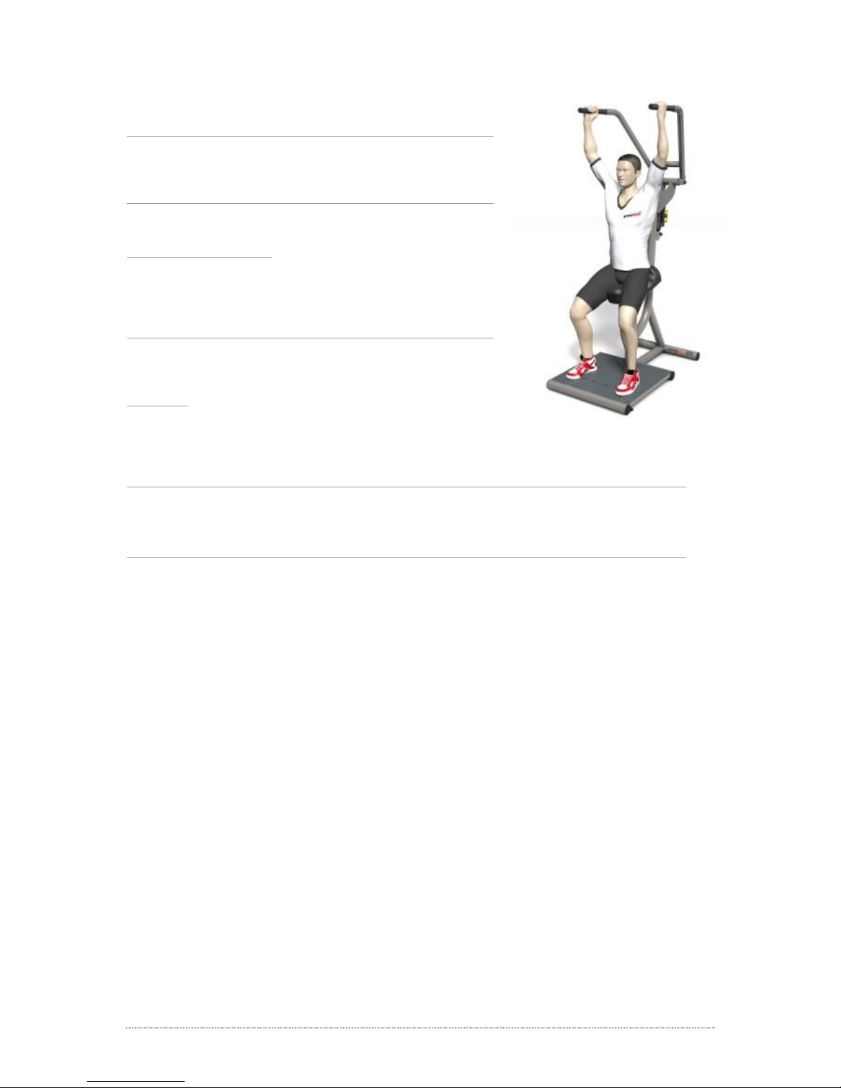
8.3 Pulldown/ Shoulder press, Art. 10666400 .................................................................................................11
8.4 Chest press/Rowing, Art. 10666200 ..........................................................................................................12
8.5 Back extension/flexion Art. 10666600 .......................................................................................................13
8.6 Butterfly/Butterfly Reverse Art. 10666300 .................................................................................................14
8.7 Hip extension left, Art. 10666700 .............................................................................................................15
8.8 Hip extension right, Art. 10666800 ...........................................................................................................16
8.9 Squad, Art. 10666500 ..............................................................................................................................17
8.10 Chest press/Rowing vertical, Art. 10667000 ..............................................................................................18
8.11 Important Training Advices........................................................................................................................19
9Maintenance and Service ......................................................................................................................19
9.1 General ....................................................................................................................................................19
9.2 Maintenance Manual of the Equipment for the Operator ..........................................................................19
9.3 Maintenance Manual for the Hydraulic Resistance Disposer for the Operator .............................................20
10 Warranty ................................................................................................................................................21
10.1 Customer Service ......................................................................................................................................21

User Manual Page 4 of 22 Version 1.2
1General
You have chosen to purchase our training equipment. For this trust, we thank you.
The "Core Circuit" line composes of compass 200 –205. The products of the "Core Circuit" were designed by taking
into account recognized biomechanical findings, as well as anatomical and physiological considerations and serve the
training of different muscle groups.
The units have undergone extensive safety controls to prevent possible injury. Read the instructions
manual but with all the safety instructions and warnings before using the exercise equipment
carefully to ensure a safe and proper use.
Important notices, alerts and warnings are highlighted in the manual with the adjacent plate
2Identification and Specification, General Warnings
2.1 Identification and Specification
This manual is valid for the following devices:
Core Circuit with mechanical resistance setting
Art. Device
10666100 Ab-/Adductor
10666400 Pulldown/Shoulder Press
10666200 Chest Press/Rowing
10666600 Back extension/flexion
10666300 Butterfly/Butterfly reverse
10666700 Hip extension left
10666800 Hip extension right
10666500 Squat
10667000 Chest press/Rowing vertical
2.2 Range of Application
The corecircuit units are used for training the strength and endurance of the muscles and are designed for use in
sport gyms, prevention premises and outside the EU in medical facilities. The devices are provided, depending on the
exercise equipment, for a comprehensive training of various parts of the skeletal muscles in a concentric form of
training for male and female up to a body weight of 200 kg and height of 2,00 m. The individual device-specific
applications are described in chapter 9. The units can be used in any case only under the guidance of an experienced
coach, who is familiar with the equipment. Particular suitable is the core circuit in the field of circuit training in form
of a circle.

User Manual Page 5 of 22 Version 1.2
2.3 General Warnings
-The training devices may be used only in areas, in which access and supervision is regulated specifically by the
owner. The extent of supervision is dependent on the users and that of their degree of reliability, age, experience,
training, etc. The equipment must be supervised by qualified persons (e.g., Athletic Trainers, physical therapists,
licensed or instructed Coach) and may be used after extensive training by appropriate persons.
-The use of additional resistors (additional weights, manipulation of hydraulics) is in any form not allowed and will
void the warranty and guarantee claims.
-The explosive strength training isn’t allowed. The training should be performed in a symmetrical moderate speed
to avoid pressure peaks in the training system and on the user.
-The loading is focused on the strength endurance training. The intensity level is depending on the speed of
movement by this resistance system. The training speed faster, the load will be higher. An explosive training
should be avoided in any case.
-This resistance system is specially designed for training of strength endurance. Exercising in higher load ranges is
possible. The maximal strength training is not provided on this machine,
-Disabled people, children and people with heart and circulatory problems may not train without assistance or
supervision.
-Children should not be unattended neither may not stay close to the devices nor use the devices.
-During training no one should be near the moving parts (hydraulic, piston, lever arms, etc.). A safe distance
(clearance) of at least 1.3 meters needs to be guaranteed to avoid any risk of injury by swinging parts (especially
during extension of Hip device). The units of left and right hip extension need to be placed directly, but with
suitable space for the implementation of the exercise, close to a wall.
-Only use the device as intended described in chapter 9.
-If any malfunction happens at a device, it needs to be left and may not be used anymore. The unit is clearly to be
indicated that it is out of order to prevent an unauthorized use of the defective device. The failure should be
identified and reported to the manufacturer or dealer responsible in your country.
-Failures, which affect the function of the machine or even can cause an injury, have to be repaired, otherwise
liability cannot be accepted.
-Do not grip with the hands between moving parts.
-No adjustments may stick out, which can hinder the movement of the athlete. Dangerous spots are indicated with
following plate:
Caution
Moving Parts
Risk of Injury
Ensure your own safety by taking care of following points:
-Before starting any exercise it needs to be ensured that all locking pins are locked and tight completely. During
exercising adaptations may not be done at any adjustments.
-During the training the athlete should wear light-weight, breathable and tight-fitting clothing.
-Please stop the training on the devices, if the athlete feels uncomfortable. If sickness, dizziness and headache
occurs consult the medical doctor.
-Training on the devices may only be carried out under appropriate supervision.
-Before starting a training please take care of the proper biomechanical adjustments with attention to the pivot
point, joint alignment. Pay attention to the tight locking of the adjustments. No adjustments may stick out.
-The settings on the devices should be made with due care. Please read the relevant parts in the manual.
-The training may not be achieved as an explosive power training. The training needs to be carried out smoothly in
uniform speed to prevent high pressure peaks.
2.4 Safety Note
-It is to ensure, in particular during changing the position of the device without dismantling that the devices are
positioned stabile on the even surface.

User Manual Page 6 of 22 Version 1.2
-Existing housing should not be dismantled.
-The warranty is invalidated, if changes are made on the device or electronic control panel, which are not approved
by the manufacturer and if the work is done by a not authorized person.
-Defective parts of the device must be replaced immediately - thereby it is necessary that up to the repair of the
unit the device will not be used. Use only original accessories, otherwise no liability.
-Note that the carrying capacity of the ground must be according to the weight of the devices in combination with
the maximum user weight (200 kg).
-Use the device only in dry air and sea water free spaces (<65% humidity) and avoid the use of rooms in
temperatures below 5 degrees and higher 45 degrees Celsius.
3Identification of User Manual
-The version is indicated on the last page.
-If modifications require a change by the manufacturer, a new version number identifies the correct version.
4Modification of Products
Modifications of products may generally be carried out only with original parts from the manufacturer and by
authorized person.
Modifications in the manual need to be inserted on the appropriate page.
Any modifications that are not performed by authorized person lead to the loss of warranty. This includes in particular
the increase in the resistance of any kind beyond the resistance defined by the manufacturer.
5Importance of the User Manual
The manual is part of the product you have purchased and needs to be retained and attended during the life time of
the product.
The manual needs to be passed to any subsequent owner. For subsequent owners with a different language please
ask for a separate user manual.
The user must ensure that all received amendments are included in the manual.
The above points are valid for accessories. It can be written by the manufacturer reordered requisition for payment for
lost instruction manual.
6Preparation of Product for First Use
6.1 Transport
The devices are normally delivered fully assembled by our staff, authorized dealer or forwarding company.
The manufacturer is not liable for transportation-related claim, damage or missing parts which are
not recorded in writing immediately on receipt for the delivery documents.
6.2 Storage
The storage area should be as well as at site of use of the devices to be dry, free of sea water and dust resistant and
can provide a storage temperature between +5 ° C to 45 ° C. Protect them from bumps, scratches and moisture.
6.3 Installation
The unit must be positioned in balance on an even, firm and load-resistant floor, which withstands a resistance of the
device plus the maximum allowable weight of 200 kg. In the case of uneven surface the floor needs to be equalized
by an appropriate material as metal plate or heavy duty plastic to get a flat surface. It is to be ensured that the

User Manual Page 7 of 22 Version 1.2
compensation materials not prone to rust. The device has two feet, which can be adapted to compensate
irregularities.
For damping, we recommend to set buffer material made of rubber, which can be purchased as accessories. Take
care in case of PVC floor that the rubber sheets and feet can cause reactions with the PVC material. Please use
appropriate cork.
Avoid hard, sudden placement of the devices.
An important prerequisite for the proper functioning of the device is the alignment with a spirit level. The devices are
for freestanding use.
The installation of the devices in high traffic areas or near doors and passageways should be avoided.
6.4 Setting-up Operation
Before setting-up please check the proper and correct condition of:
Hydraulics for visible damage, particular the applicable end mounting.
Locking pin to function, locking knob needs to engage independently.
Stability.
Bolt connections –prove the firm bonding.
Welds –visual examination.
Moving function OK.
Check before every usage:
Locking bolts for secure fixation
resistance setting on the resistance system
7Hydraulic Resistance System
The hydraulic resistance system is available with mechanical load control. The mechanical system allows an
adjustment of the resistance with the piston by using the knob, which can be turned. Here are appropriate
for the adjustment of the load acting on bidirectional two and one-directional one knob available. Thus a
differential resistance variation for antagonistic mode is possible. The built-in piston requires a direct
connection to the lever arm. Deflections by ropes or straps are not done. The adjustment knobs of the
piston in the mechanical are free accessible.
The amount of exercises is focused on the area of endurance muscle training. The stress intensity is at the
right resistance system according to the speed of the executed movement. The faster the training speed is
the greater the strain on the trainees. This is to be considered for training. An explosive training is to be
avoided in any case.
An increased training speed also leads to increased stress perception during exercise.

User Manual Page 8 of 22 Version 1.2
Description of mechanical piston
7.1 Details for the Mechanical Model of the Hydraulic Resistance System
The mechanical control of the resistance is carried out in bi-directional devices via two adjustment knobs, in
unidirectional devices (extension Squat / Hip) by one knob. The resistance scale ranges from 1-6. The range of the
resistance allows a training of 1 (very easy) to 6 (very difficult) for the normal population of women. The training with
the resistance system is designed specifically for endurance muscle training. Exercising in higher load ranges is
possible. A maximum strength training on the equipment is not provided, and because of the limited maximum
resistance setting only for a few trainees possible and only on some devices. The middle setting 2-3 is based on the
average performance of middle-aged women.
Description of mechanical piston
The wheel knobs for adjusting the resistance may not be adjusted during the
training or during the movement of the damper!
Boss
Piston Rod
Filling valve
Dial
Boss
Control
Unit
main cylinder
Balancing Cylinder

User Manual Page 9 of 22 Version 1.2
7.2 Technical Data of Hydraulic Resistance Encoder
Length (boss to boss)
:
580
Mm
Maximum levitation height
:
210
Mm
maximum width
:
78
Mm
Width of boss
:
20
Mm
Width connecting link
:
25
Mm
Bracing
:
70
N
Maximum force
:
4
KN
Damping consistence
:
Silicon Oil
Supply voltage
:
6
V (DC)
Burst pressure Cylinder
:
320
Bar
Maximum pressure seal
:
60
Bar
System pressure
:
2 - 15
Bar
7.3 Special safety Instructions for the Hydraulic Resistance System
Maintenance may only be conducted by authorized persons appointed by proxomed. During servicing
wearing of protective eyewear is mandatory. Due to the technical structure of the damper during
maintenance a spontaneous and explosive pressure could be released. The filling pressure is 3.5bar.
The user is responsible to ensure that the damper is not nudged to the frame or components of the
equipment, if it is replaced or assembled. The clearance should be checked over the entire levitation length
of the damper!
The mounting screws must be checked periodically for tightness.
The hydraulic resistance system changes its resistance characters depending on the training speed.
For faster training speed is a higher impact to be performed. This fact needs to be taken in
account during training.
8Exercise Guidance and Technical Data for the Training Devices
The positioning of the customer needs always to be done with utmost care, because quality and effectiveness of the
exercise performance are highly dependent on a correct starting position.
On most devices training is performed in a sitting or semi-standing position. The back, especially the lumbar spine,
should be stabilized as much as possible during the exercise. The devices axes and pivot points must be adjusted as
closely as possible to the axes of the respective joints to prevent the occurrence of compression and shear forces. The
resistance should be chosen that the client / trainee can perform the training without evasive movements. The load
change is made by the resistance system mounted wheel knob.
8.1 Common Training Advices
Before starting to train the customer should, for example, warm up on a cycle ergometer followed by stretching
exercises and preparing the appropriate muscles to the upcoming load.
If symptoms occur, the exercise needs to be stopped and if necessary the doctor needs to be consulted.
The devices enable customers to do a concentric / concentric training and to avoid high eccentric stress on muscles.
The movement should be slow and controlled, making sure that the correct motion is performed. The exercise
intensity should be chosen at the start of training, which should be light. The load can then be increased gradually to
avoid congestion that can cause problems and pain for the customer / training person.

User Manual Page 10 of 22 Version 1.2
Quick strengthening exercises, in which the movement would be explosive, are prohibited. A controlled
motion control must be always guaranteed to avoid biomechanical stress and injury.
There are many different training methods possible. If trained by the repetition method, several series of exercises are
performed with appropriate breaks. The exercise intensity is based on the strength of the muscular structures of the
customer and depending on the training target.
It may be useful to adapt and get used to injured structure (connective tissue, cartilage, tendons, ligaments and joint
capsule) and to choose for a weight load with low intensity, before training of special force skills - starts with
increasing intensity - such as muscular endurance or maximum strength.
8.2 Ab-/Adductor, Art. 10666100
Purpose of Use
At this unit all muscle groups are effectively trained, which are needed for
the abduction and adduction of the leg. These muscle groups cover as well
pelvic as hip area and the knee joint stabilizing.
Specific Positioning of Customer
Starting Position/Positioning:
Fix your back stable to the rear cushion. Position the upper leg bent in
knee joint into the pads, the lower legs are supported by appropriate
cushions. Raise the upper body by active stabilization of the handles.
Tiptoe for self-stabilization by flexing the foot.
Movement Description:
Open (abduct to the outside) and close (adduct to inside) the leg –range of motion depending on
individual mobility- . The start of motion is done by slight pressure only on the thigh pad. The lower limb
pads are used only to support the legs and have deliberately not a support for performing the movement.
Special notes:
If hip problems are known both directions of movement should be performed slowly and cautiously.
Conduct only motions up to the point that there are no alternate movements in the hip or back.
Performing Muscles
Adductor: M. adductor magnus M. adductor longus M. adductor brevis M. pectineus
M. gracilis
Abductor: M. glutaeus medius M. glutaeus minimus M. tensor fasciae latae M.
piriformis
Technical Data
Dimensions (L x W x H): 120x80x135 cm
Total Weight: 102 kg
Maximum Allowance of Body Weight: 200 kg

User Manual Page 11 of 22 Version 1.2
8.3 Pulldown/ Shoulder press, Art. 10666400
Purpose of Use
At this unit firstly shoulder blade muscles are trained, which have special
importance for the upright, spine-friendly posture. In the second function
the neck surrounding muscles are trained.
Specific Positioning of Customer
During exercising the customer should take special notice to an upright
posture of the trunk.
Starting Position / Positioning:
Adapt the height of the saddle seat up to a half-standing seat positioning.
Position the feet by aligning the marks on the foot plate. Grip the handles
tightly. Raise the upper body by stabilizing the feet and by flexing the back
and abdominal muscles and stabilize active.
Movement Description:
Only extend the arm up to not full extension. Flex the arm until you have
reached the height of the shoulder. Perform the motion on both sides
equally.
Special Note:
Chose for a more frontal or rear handle position depending of the range
of motion of your shoulder joint. Perform only the extension up to the point you are not doing alternative movement
in the shoulder- and / or spine area. Keep your hands always in the extended position of your arms. In general you
only may train in pain-free range of motion, if necessary limit the range of motion.
Performing Muscles
Pulldown: M. latissimus dorsi M. pectoralis major M. subscapularis M. deltoideus
M. teres major M. biceps brachii Mm. Rhomboidei M trapezius
Shoulder Press: M. trapezius M.deltoideus M.triceps brachii M. serratus anterior
Technical Data
Dimension (L x B x H): 120x80x155 cm
Total Weight: 102 kg
Maximum Allowance of Body Weight: 200 kg

User Manual Page 12 of 22 Version 1.2
8.4 Chest press/Rowing, Art. 10666200
Purpose of Use
At his devices are trained by doing a rowing motion all the dorsal muscles
of the shoulder girdle, arm flexion muscles and the back muscles mainly in
the thoracal aera, which are responsible for an upright spine posture.
In implementing the chest press movement the chest and arm extension
muscles are trained.
Specific Positioning of Customer
During exercising the customer should take special notice to an upright
posture of the trunk.
Starting position / Positioning:
Adapt the saddle height according to a half-standing position. The feet
should be aligned on the markers at the footplate symmetrically.
Raise the upper body by stabilizing the feet and by flexing the back and
abdominal muscles and stabilize active your core muscles. Grip the handles
firmly in height of the chest.
Movement Description:
Move the arms in a harmonious movement back and forth. If extending the arm, do not fully extend the ellbow joint.
Lead the elbows laterally parallel to the body (or slightly raised).
Special Note:
Make sure that the shoulders remain during the entire movement execution in a neutral position. To stabilize the
shoulder girdle perform during exercising a back-pull down movement of the shoulder blades. If it is necessary,
reduce the range of motion in the pull phase, or change the placement of the hands.
Performing Muscles
Rowing: M. latissimus dorsi M. biceps brachii M. trapezius M. deltoideus
M. teres major Mm. rhomboidei
Chest press: M. pectorialis major M. deltoideus M. triceps brachii M. serratus anterior
Technical Data
Dimensions (L x W x H): 120x100x145 cm
Total Weight: 103 kg
Maximum Allowance of Body Weight: 200 kg

User Manual Page 13 of 22 Version 1.2
8.5 Back extension/flexion Art. 10666600
Purpose of Use
At this unit is trained by bending forward and backwards the trunk the dorsal and ventral trunk and core
muscles.
Specific Positioning of Customer
Starting position / Positioning
Adapt the saddle seat depending on body height to an appropriate height that a half-standing position is
received. The feet should be aligned on the markers at the footplate symmetrically. Forearms need to be
balanced in stable position at or on the padded rollers. Use the handles, if necessary, to facilitate the
control (not a requirement!). Stabilize the upper body and shoulder girdle by active tensing the torso
muscles.
Movement Description:
Before the initial phase of flexion contract the abdominal muscles, especially the core muscles. Start by
contracting the flexor muscles by initialization of strength on the forearm pad and roll the upper body with
segmental diffraction. In the extension movement extend the trunk by pressing against the roll pad.
Head control: in the flexion phase the chin needs to lead to the chest by rolling in the trunk. In the
extension phase the head should only be extended up to the extension of the back.
Special note:
Do perform the flexion up to the point no pelvic flexion happens. In the extension movement do stop at
the normal physiological lordosis. Always control the movement by not swinging. The breathing-out needs
to be done in the flexion phase. With problems in the lumbar spine perform only very cautious and slowly.
Performing Muscles
Back extension: M. erectores M. longissimi M. interspinales
Back flexion: M. rectus abdominis Mm. obliqui abdomini M.transversus abdominis
Technical Data
Dimensions (L x W x H): 120x80x155 cm
Total weight: 115 kg
Maximum allowance of body weight: 200 kg

User Manual Page 14 of 22 Version 1.2
8.6 Butterfly/Butterfly Reverse Art. 10666300
Purpose of Use
On this device all the muscle groups of the back and the thoracic spine are
trained, which are responsible for straighten the spine and stabilize the
shoulder. Likewise all muscle groups are trained, which are responsible for
the anterior stabilization of the shoulder girdle.
Specific Positioning of Customer
Starting position / positioning:
Adapt the saddle seat depending on body height to an appropriate height
that a half-standing position is received. The feet should be aligned on the
markers at the footplate symmetrically. Raise the upper body by stabilizing
the feet and by flexing the back and abdominal muscles and stabilize
actively. The flexed arms are placed in the cushions symmetrically. The
hands grasp the handle loosely.
Movement description:
Start the movement with forward and backward motion by pressing
smoothly into the forearm pad: During the forward movement press
slightly inside, during the outside movement to the outside. Move to the
outside only so far that there is no alternate movement in the shoulder and back.
Special note:
Chose for a seat height that the shoulder can be held in a neutral position comfortably. Flourishing
movements should be avoided at the reversal point.
Performing Muscles
Butterfly: M. pectoralis major M. deltoideus M. biceps brachii
Buitterfly reverse: Mm. rhomboidei M. trapezius M. deltoideus M. latissimus dorsi
Technical Data
Dimensions (L x W x H): 120x100x145 cm
Total Weight: 103 kg
Maximum allowance of body weight: 200 kg

User Manual Page 15 of 22 Version 1.2
8.7 Hip extension left, Art. 10666700
Purpose of use
On this device the total left hip extension muscles are trained.
Specific Positioning of Customer
Starting position / Positioning:
Place the forearms on the pad symmetrically. If necessary, grap the handle. The standing leg should be slightly bent
and the foot should be placed parallel to the marker on the foot plate. Place the right foot on the moveable footplate
and the toe should flush with the edge. The inclined trunk should have a straight back. Stabilize actively the core and
trunk muscles during exercising.
Movement description:
Start the movement by giving pressure on the footplate and extend the leg but not completely. After that bring the
leg slowly and controlled to the starting position. The movement starts a little in front of the standing leg (depending
also of the range of motion).
Special note:
Avoid an evasion of the knee. It should be a straight-line movement. Give special attention to the pelvis that not a too
much of lordosis or sidewards flexion happens. Make also sure that the right standing leg does not extend beyond
the central marker in the range of motion of the left leg.
Performing muscles
M. glutaeus maximus M. ischiocrurales M. biceps femoris M. semitendinosus M. triceps surae
M. quadriceps femoris M. erector spinae lumbalis
Technical Data
Dimensions (L x W x H): 140x80x135 cm
Total weight: 107 kg
Maximum allowance of body weight: 200 kg

User Manual Page 16 of 22 Version 1.2
8.8 Hip extension right, Art. 10666800
Purpose of Use
On this device the total right hip extension muscles are trained.
Specific Positioning of Customer
Starting position / Positioning:
Place the forearms on the pad symmetrically. If necessary, grap the
handle. The standing leg should be slightly bend and the foot should be
placed parallel to the marker on the foot plate. Place the left foot on the
moveable footplate and the toe should flush with the edge. The inclined
trunk should have a straight back. Stabilize actively the core and trunk
muscles during exercising.
Movement description:
Start the movement by giving pressure on the footplate and extend the
leg but not completely. After that bring the leg slowly and controlled to
the starting position. The movement starts a little in front of the standing leg (depending also of the range of motion).
Special note:
Avoid an evasion of the knee. It should be a straight-line movement. Give special attention to the pelvis that not a too
much of lordosis or sideward flexion happens. Make also sure that the left standing leg does not extend beyond the
central marker in the range of motion of the right leg.
Performing muscles
M. glutaeus maximus M. ischiocrurales M. biceps femoris M. semitendinosus M. triceps surae
M. quadriceps femoris M. erector spinae lumbalis
Technical data
Dimensions (L x W x H): 140x80x135 cm
Total weight: 107 kg
Maximum allowance of body weight: 200 kg

User Manual Page 17 of 22 Version 1.2
8.9 Squad, Art. 10666500
Purpose of Use
The device allows a complete training of the leg extension loop.
Specific Positioning of Customer
Starting position / Positioning:
Place the shoulders under the cushion. Grap the handles firmly. Place the
feet according to the markers on the footplate symmetrically. Important:
the knee joint may not extend beyond the toes. Bend slightly the trunk
forward and stabilize actively the torso muscles by contracting the core.
Movement description:
Lower your trunk by bringing the buttocks backwards firstly until the anlge
in the knee joint reaches 80° (reference value: neutral-zero). The straighten
movement needs to be carried out by starting with the shoulder. Only
extend so far that the knee is slightly flexed. Take attention to a rectilinear
motion with constant knee distance.
Special note:
Keep your upper body stable (to avoid evasion of the pelvis) by activating
trunk muscle. Keep your arms sideward next to the body. Avoid swinging
movements. With problems in the lumbar spine perform only very cautious
and slowly.
Performing muscles
M. quadriceps femoris M. glutaeus maximus M. triceps suraeM. erector spinae
Technical data
Dimensions (L x W x H): 120x80x145 cm
Total weight: 97 kg
Maximum allowance of body weight: 200 kg

User Manual Page 18 of 22 Version 1.2
8.10 Chest press/Rowing vertical, Art. 10667000
Purpose of Use
At his devices are trained by doing an upwards rowing motion all the
dorsal muscles of the shoulder girdle, arm flexion muscles and the back
muscles mainly in the thoracic area, which are responsible for an upright
spine posture.
In implementing the downwards chest press movement the chest, arm
extension muscles and the stabilizing muscles of shoulder girdle are
trained.
Specific Positioning of Customer
Starting position / Positioning:
Adapt the saddle height according to a half-standing position. The feet
should be aligned on the markers at the footplate symmetrically.
Raise the upper body with a straight back into light tilt forwards position,
hold the handles symmetrically with fixed wrists. Actively stabilize the back
and abdominal muscles through consciously contracting in this body
position.
Movement Description:
Move the arms in a harmonious movement back and forth. If extending
the arm, do not fully extend the ellbow joint. Lead the elbows laterally
parallel to the body (or slightly raised).
Special Note:
Make sure that the head and upper body in light tilt forwards position form a line (sight to the front-bottom). Avoid
co- and compensatory movements of the head in any case. The shoulders remain in a neutral position during the
entire movement execution. To stabilize the shoulder girdle perform during exercising a back-pull down movement of
the shoulder blades. If it is necessary, reduce the range of motion in the pull phase, or change the placement of the
hands.
Performing Muscles
Rowing: M. latissimus dorsi M. biceps brachii M. trapezius M. deltoideus
M. teres major Mm. rhomboidei
Chest press: M. pectorialis major M. deltoideus M. triceps brachii M. serratus anterior
Technical Data
Dimensions (L x W x H): 125x80x100 cm
Total Weight: 90 kg
Maximum Allowance of Body Weight: 200 kg

User Manual Page 19 of 22 Version 1.2
8.11 Important Training Advices
The training exercises should be performed always painless. When symptoms occur, training must be
stopped. A doctor or therapist should be consulted.
The load of the muscles during exercise is only concentric.
The training pace should be moderate. Explosive training should be avoided.
The resistance system has a fixed maximum load setting, which cannot be exceeded. This is adaptable
individually for each device. A resistance of this maximum is for safety reasons not possible.
The intensity should be chosen easily at the start of training. The load is then increased gradually to avoid
congestion that can cause problems and pain for customers.
If the training on core circuit is used improper or excessive, it can harm your health.
9Maintenance and Service
9.1 General
The training equipment of the Core Circuit with hydraulic resistance system needs to be checked up
at least every 2 years by the manufacturer or an authorized service partner
9.2 Maintenance Manual of the Equipment for the Operator
Despite the excellent quality of the devices checks needs to be done time to time (1-2 months) for security
reasons:
Control all electrical components in wear-prone parts such as wheels, screws, bolts and in particular the
hydraulic resistance system, and its attachment to strength and damage. To maintain the technical level of
safety of the device damaged wear parts needs to be replaced with original parts. The equipment needs to
be taken out of service until it is repaired.
Clean panels and frame parts regularly with a damp cloth and mild soap to remove corrosive sweat
residue. After the training operation disinfect the pad contact with commercially available disinfectants.
Pins and set screws, where needed, need also to be greased.
Hydraulic resistance disposers also require following maintenance every 3-4 weeks
Check all screws are tight.
Study the resistance disposer on leakage.
Clean the resistance rods and use special oil for smooth operating.
Spray all joint parts (also resistance disposer) with special oil.
Note!
If you notice an unexpected damage, stop exercising immediately and inform the instructor.
If you cannot solve the equipment malfunction easily, inform the manufacturer proxomed or authorized
dealer for repair. The authorized service will help you quickly and competently or give you a tutorial. Device
needs to be blocked and needs to be marked with “out of order” sign.

User Manual Page 20 of 22 Version 1.2
9.3 Maintenance Manual for the Hydraulic Resistance Disposer for the Operator
Basically, the damper is kept clear with its sliding surfaces of gross pollution. The sliding surface of the piston rod is to
be exempted on a regular basis to remove dirt and dust residue. After cleaning it is recommended to treat the sliding
surface with suitable lubricants from the manufacturer. The proper lubricant can be obtained from proxomed.
The damper cannot be cleaned with harsh detergents. When cleaning, make sure that the caps of the valves are
unscrewed.
Dilutions and aggressive cleaning agents can damage the surfaces, seals and stickers of the damper and
may not be used. (alcohol, acetone, brake cleaner, etc.)
The surfaces of the damper are made of anodized aluminum and then react to UV light, which can lead to slight color
changes. Particularly in the area of stickers and hidden areas, this effect can lead to color shade. The function of the
damper is not affected.
Check-up and filling of the system pressure
The hydraulic unit operates with an air spring that biases the oil column with a floating piston. The filling valve is
normally protected at the front part with a protective cap.
Before checking and / or filling of the system pressure it is suitable to wear goggles and to expand the
damper.
Steps for filling and check-up:
- Carefully remove the cap
- Unscrew the pump with suitable tools
- Check the pressure! Set pressure = 2 - 3.5bar!
- If pressure is < 2 - 3.5 bar, re-inflate up to set pressure.
- Carefully remove the pump again.
- Screw the cap
Table of contents
Other Proxomed Fitness Equipment manuals

Proxomed
Proxomed Compass 530 User manual

Proxomed
Proxomed kardiomed 521 User manual

Proxomed
Proxomed compass MTT User manual

Proxomed
Proxomed kardiomed 530 User manual

Proxomed
Proxomed Compass 600 User manual

Proxomed
Proxomed tergumed 710 User manual

Proxomed
Proxomed tergumed 710 User manual

Proxomed
Proxomed compass 210 Abductor User manual

Proxomed
Proxomed Intensic Abductor User manual

Proxomed
Proxomed kardiomed 521 User manual