PS Industries PS Safety Access EdgeSafe Series Operation and maintenance manual

1
ESR Series
Rev081921
© 2021 PS Industries®Incorporated. All Rights Reserved.
Installation Instructions/Operation and Maintenance Manual
Models:
All Models
IMPORTANT! Read entire Instruction and Operations Manual to become familiar with the product.
NOTICE This product is a safety protection product. The effectiveness of the product is directly related to the proper
installation and operation of this product. Failure to properly maintain this product will affect performance.
Publication Notice
This manual has been compiled and published covering the latest product descriptions and specications.
The contents of this manual and the specications of this product are subject to change without notice.
PS Safety Access™ reserves the right to make changes without notice in the specications and materials contained
herein and shall not be responsible for any damages (including consequential) caused by reliance on the materials
presented, including but not limited to typographical and other errors relating to the publication.
PS Safety Access and/or its respective suppliers may make improvements and/or changes in the product(s)/
service(s) offered and/or the program(s) at any time without notice.
Retain this manual for future reference.
If you would like to download a copy of this manual, please go to pssafetyaccess.com
Product registration is an essential step to protecting your product, register Online at
psindustries.com/contact/register-your-product/
Mail
PS Safety Access
1150 South 48th Street
Grand Forks, ND 58201
Website
pssafetyaccess.com
Email
Local Phone
701.746.4519
Toll Free Phone
877.446.1519
Hours of Operation
8 A.M. to 5 P.M. CT
Monday – Friday
Contact Information
Table of Contents:
Safety Precautions ............................................................. 2
Product Information ........................................................... 2
Operation............................................................................ 3
Installation Instructions..................................................... 4
Toe Board Installation Instruction..................................... 8
Replacement Parts List ...................................................10
Inspection and Maintenance...........................................11
Warranty Certicate .........................................................12
PN 515609 A

2ESR Series
Rev081921
© 2021 PS Industries®Incorporated. All Rights Reserved.
NOTICE Unauthorized modication of or to the Product voids this Limited Warranty. Authorized modications,
received in writing from PS Industries® Incorporated, as long as the modication is accomplished in strict
accordance with PS Industries’ instructions, does not void warranty. If this product is modied or altered
without manufactures permission, manufacturer is no longer responsible for the product design, engineering,
or performance and owner assumes all responsibility. To request product modications contact PS Industries
Incorporated, 1150 S. 48th Street, Grand Forks, ND 58201, phone 877-446-1519, email: 4psinf[email protected]
I. General Information
A. This manual contains information regarding installation, operation, and maintenance of the PS Safety Access’
EdgeSafe® Safety Railing.
B. PS Safety Access recommends that the owner implement a regular preventative maintenance program to
inspect and maintain the Pallet Gate at a minimum, in accordance with the recommendations in this manual.
II. Operation Guidelines
A. The Safety Railing is designed to meet:
1. OSHA Railing Standard 1910.29(b), and ANSI A1264.1-2017.
2. Canada OHS SOR-86-304 Sections 2.12 and 2.13.
B. Operation in a manner other than intended could result in damage or less than acceptable performance at time
of need, for which the manufacturer will not be held responsible.
III. Safety Precautions
A. Ensure opening is clear of all obstructions.
B. Comply with all OSHA and ANSI Safety Regulations and/or company safety policies when installing.
WARNING Do NOT force components if they do not operate freely.
DANGER Ensure area below installation is blocked off from personnel during installation, and mounting surface
is capable of supporting all loading. Structural analysis of mounting surface is the responsibility of the owner.
IV. Storage Prior to Installation of Product
A. Store materials in a dry, ventilated location. If outdoor storage is required, block materials and tarp in a tent-like
arrangement, elevated above the product with open sides to allow airow.
V. Installation Site Preparation
NOTICE Before starting site preparation and installation of the Safety Railing, read the entire Operation and
Maintenance Manual and review all additional installation instructions thoroughly.
A. Clear work area of any debris.
B. Ensure you have the necessary tools available.
C. Obtain all required permits.
D. Personnel: Determine the appropriate number of personnel required to perform installation and have them
readily available at the project site (1-2 people recommended).
E. Ensure all installation personnel utilize appropriate fall protection equipment and procedures during
installation.
Safety Precautions
Product Information
The following icons are used throughout this Manual.
DANGER Indicates an imminently hazardous situation which, if not avoided, will result in death or serious injury.
WARNING Indicates a potentially hazardous situation which, if not avoided, could result in death or serious injury.
CAUTIONCAUTION Indicates a potentially hazardous situation which, if not avoided, may result in minor or moderated injury.
NOTICE Indicates manufacturer’s statement of additional information.
IMPORTANT! Indicates a required action.
CRITICAL Indicates a vital component to product performance.

3
ESR Series
Rev081921
© 2021 PS Industries®Incorporated. All Rights Reserved.
Product Information
VI. Recommended Tools for Installation:
A. Tools:
1. One (1) 1/2” (13mm) Socket and Ratchet
2. Two (2) 1/2” (13mm) Wrenches
3. One (1) 1/2” (13mm) Nut Driver and Impact Drill
4. One (1) 5/32” (4mm) Allen Wrench
5. One (1) Tape Measure
6. One (1) Level
7. One (1) Rubber Mallet.
8. Depending on anchoring conguration, additional tools may be required.
VII. Safety Railing Part List
A. Review inventory to ensure all parts are present for assembly/installation. Refer to part list below.
Safety Railing Part List
(As shipped)
ITEM # DESCRIPTION QTY
1 EDGESAFE SAFETY RAILING POST *
2 EDGESAFE SAFETY RAILING BRACKET *
3 EDGESAFE SAFETY RAILING RAIL *
4 EDGESAFE SAFETY RAILING TB *
*Quantity is dependent on EdgeSafe® Safety Railing size and
conguration.
4
3
1
2
4ESR Series
Rev081921
© 2021 PS Industries®Incorporated. All Rights Reserved.
IX. Installation
NOTICE This product model has been load-tested while anchored to a concrete oor. It is the installer’s
responsibility to verify this product meets all applicable codes based on the specic installation
environment.
CRITICAL Ensure mounting surface is capable of supporting all loading. Structural analysis of mounting surface
is the responsibility of the Installer. Fasteners must be of sufcient size, grade, appropriate for anchoring
material, etc. to accept the potential loading. Consult qualied Structural Engineer.
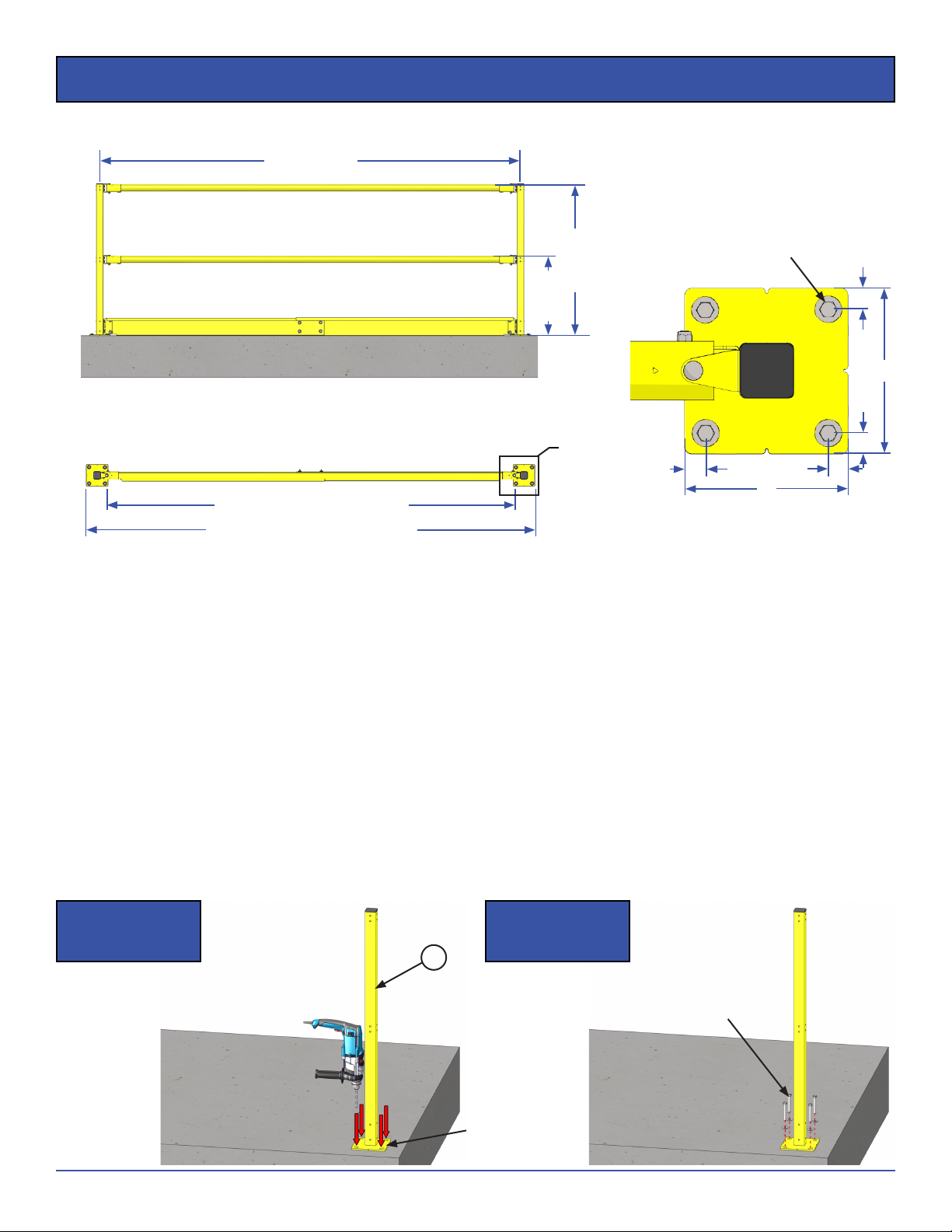
STEP 1. Place rst Post in desired location.
a. Match drill holes in base plates and install fasteners.
NOTICE Fasteners to be selected and provided by the Installer. Mounting holes in base are 7/
16”, intending a 3/
8”
diameter anchor to be used.
Step 1
Illustration I
Step 1
Illustration II
Size Reference Drawing
VIII. ESR Size Reference Drawings
INSIDE EDGES OF BASE PLATES
OUTSIDE EDGES OF BASE PLATES
A
FRONT VIEW
22 13/
16”
43 5/16”
DETAIL A
6”
3/4”3/4”
TOP VIEW
6”
3/4”3/4”
8’ O.C. MAX’
(if used for fall protection)
NOTICE Post anchorage
supplied by Installer
1
Match Drill
NOTICE Post anchorage
supplied by Installer
5
ESR Series
Rev081921
© 2021 PS Industries®Incorporated. All Rights Reserved.
Installation
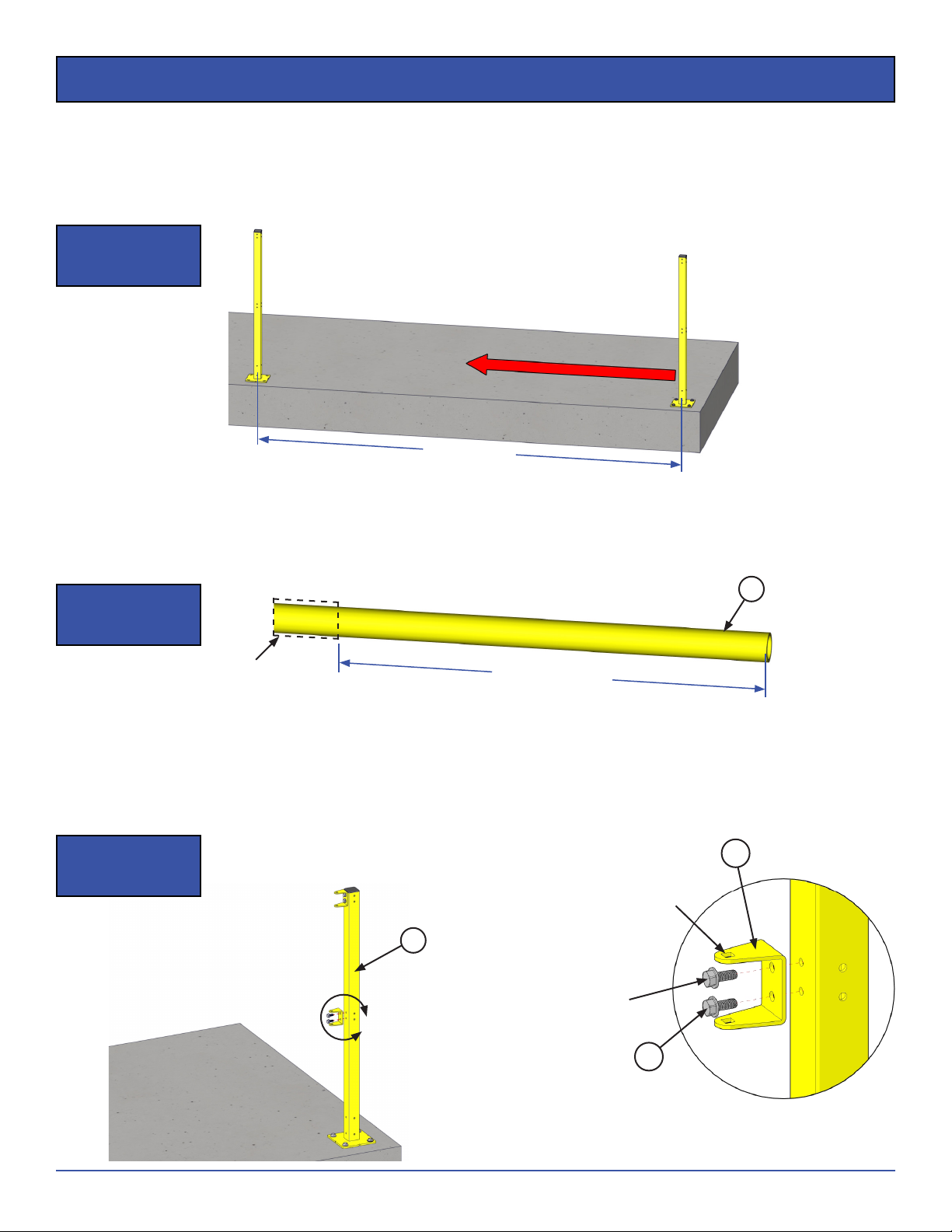
STEP 2. Place next Post in place, making sure to line up with rst Post.
a. Maximum distance for Posts is 8 ft. on center (if used for fall protection).
b. The notches in the base plate are centered on the base plates.
c. Match drill holes in base plates and install fasteners.
Step 2
Illustration I
8’ O.C. MAX’
(if used for fall protection)
STEP 3. Measure on center distance and subtract 7” to nd length of rail and cut to length.
a. Rail can be purchased from PS Safety Access in safety yellow. Rail can also be purchased locally using
1.5” sch. 40 steel pipe.
LENGTH OF RAIL
(O.C. POST DIM. ― 7”)
Cut Railing
to Length
Step 3
Illustration I
STEP 4. Using supplied 5/
16” thread forming screws, mount Railing Brackets onto both Posts.
a. Tighten to 120 in-lbs (10 ft-lbs) max.
IMPORTANT! Discontinue use of hole immediately if it strips out or if torque is exceeded. Rotate post so hole is no
longer used or replace post.
DETAIL B
B
1
Step 4
Illustration I Railing
Bracket
5/
16” Thread
Forming Screws
2.1
2.5
3

6ESR Series
Rev081921
© 2021 PS Industries®Incorporated. All Rights Reserved.
Installation
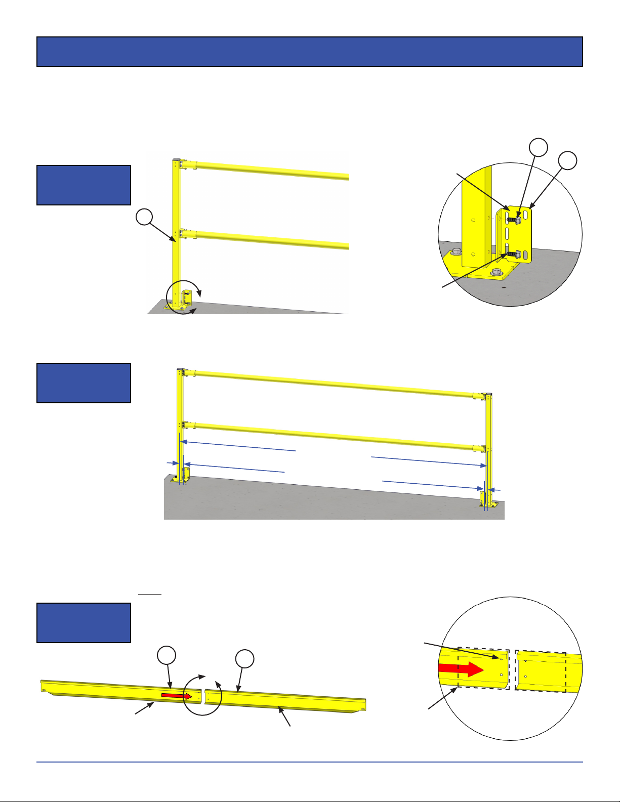
STEP 5. Attach Railing Receivers to Railing Brackets on rst Post loosely.
DETAIL C
C
1
Step 5
Illustration I Railing
Bracket
Loosely Attach
Railing Receiver
STEP 6. Slide remaining Railing Receiver onto one end of the cut railing and slide the other end of the railing into
the mounted Railing Receiver.
Step 6
Illustration I
Step 6
Illustration II
Railing
Receiver
Cut Railing
Slide Railing into
Railing Receiver
STEP 7. Pivot railing in line with Posts and mount the Railing Receiver to the Post.
Step 7
Illustration I
Step 7
Illustration II
2.2
2.6
2.4

7
ESR Series
Rev081921
© 2021 PS Industries®Incorporated. All Rights Reserved.
Installation
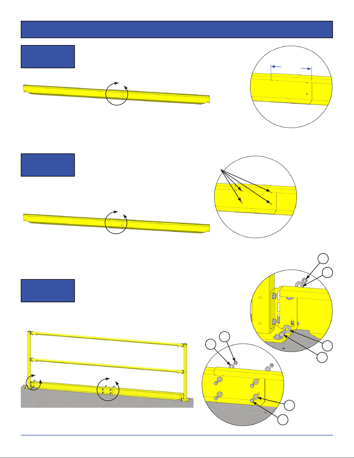
STEP 8. Center railing between Posts using triangular sight holes on top of Rail Receivers.
a. The sight holes in both Railing Receivers should be fully covered by the railing.
Step 8
Illustration I
DETAIL D
DD
Triangular
Sight Hole
Railing
End
STEP 9. Use 5/
32” (4mm) allen wrench to tighten the set screws on the Railing Receiver, from the underside.
a. Tighten to 25 in-lbs.
DETAIL E
Step 9
Illustration I Railing
Receiver
Tighten Set
Screws
E
STEP 10. Tighten nuts on Railing Brackets.
2.3
DETAIL F
Railing
Bracket
Tighten Nut
2.4
Step 10
Illustration I
F
8ESR Series
Rev081921
© 2021 PS Industries®Incorporated. All Rights Reserved.
G
1
Installation
X. Installation of Optional Toe Board
STEP 1. Use the provided 5/
16” thread forming screws and mount Toe Board Brackets.
a. For angled installation, Toe Board Brackets should be bent using an adjustable wrench to be parallel
with the railing (up to 45 degrees). Do not bend bracket more than two (2) times or strength may be
compromised.
DETAIL G
Step 1
Illustration I
STEP 2. Measure the actual on-center distance and subtract 4” to get length of the Toe Board.
Step 2
Illustration I
ACTUAL O.C. DIM.
STEP 3. Slide smaller Toe Board section inside of larger section to the length needed.
a. If the length needed is less than the length of one (1) Toe Board piece:
1). Trim both pieces down to t and re-drill holes in Toe Boards.
2). There must be at least 8” of overlap in the center of the Toe Boards.
Toe Board
Bracket
5/
16” Thread
Forming Screws
Step 3
Illustration I
DETAIL H
Cut Both
Toe Boards
to Length
Re-drill
Holes
H
Smaller
Section Larger
Section
4.1 4.2
4.3
4.7
TOE BOARD LENGTH 2”
2”
9
ESR Series
Rev081921
© 2021 PS Industries®Incorporated. All Rights Reserved.
Installation
Step 3
Illustration II
DETAIL I
8” MIN.
(OVERLAP)
STEP 4. Mark and match drill all four (4) holes in the middle of the Toe Board with 3/
8” diameter drill bit.
Step 4
Illustration I
DETAIL J
I
J
Mark and
Match Drill
STEP 5. Use provided 5/
16” bolts, at washers, and nylock nuts to secure Toe Boards in place.
a. Attach Toe Board sections with four (4) sets of hardware through the match drilled holes.
b. Bolt both Toe Board ends to Brackets with two (2) sets of hardware.
Step 5
Illustration I
DETAIL L
DETAIL K
L
K
4.5
4.5
4.6
4.4
4.4
4.5
4.5
4.6

10 ESR Series
Rev081921
© 2021 PS Industries®Incorporated. All Rights Reserved.
Replacement Parts
Replacement Parts List
ITEM # DESCRIPTION QTY PART #
1 EDGESAFE SAFETY RAILING POST * ESR-P-PCY
1.1 ESR;SURFACE MOUNT POST PCY 1 515528
1.2 PLUG;SQ 2” FINISH PLUG 1 515597
2 EDGESAFE SAFETY RAILING BRACKET * ESR-B-PCY
2.1 ESR;RAILING BRACKET PCY 1 515532
2.2 ESR;RAILING RECEIVER WELD PCY 1 515534
2.3 SCREW;SET ALLEN 5/16”-18X3/8” 1 515547
2.4 NUT;NYLOCK 5/16”18 ZN 1 501126
2.5 SCREW;HEXFORM5/16”18X3/4ZN 2 515545
2.6 BOLT;CARRIAGE5/16”18X2-3/4 GR5 1 515546
3 EDGESAFE SAFETY RAILING RAIL (7’-5”) * ESR-R-PCY
4 EDGESAFE SAFETY RAILING TB * ESR-TB-PCY
4.1 ESR;LEFT TOE BOARD PCY 1 515539
4.2 ESR;RIGHT TOE BOARD PCY 1 515541
4.3 ESR;TOE BOARD MOUNT BRKT PCY 2 515537
4.4 BOLT;HEX5/16”18X3/4GR5ZN 8 500429
4.5 WASHER;FLAT 5/16”ZN 16 501949
4.6 NUT;NYLOCK 5/16”18 ZN 8 501126
4.7 SCREW;HEXFORM5/16”18X3/4ZN 4 515545
XI. Replacement Parts List and Diagrams
A. These Replacement Parts List and Diagrams are for the EdgeSafe® Safety Railing.
Finish Options
PCY Powder Coat Safety Yellow
DETAIL M DETAIL N
4.7
4.5
4.5
4.5
4.5
4.6
4.6
4.4
4.4
4.1
4.2
4.3
3
1.1
1.2
2.2
2.5
2.1
2.3
2.6
2.4
M
N
TO ORDER PARTS CONTACT PS SAFETY ACCESS AT
*Quantity is dependent on EdgeSafe® Safety Railing size and conguration.

11
ESR Series
Rev081921
© 2021 PS Industries®Incorporated. All Rights Reserved.
Inspection and Maintenance
XII. Inspection and Maintenance
A. Environmental conditions may affect the maintenance and repair requirements of the product, and
recommended preventative maintenance frequency.
B. If any of the inspection items are found to not meet the standard IMMEDIATELY “TAG OUT” the EdgeSafe®
Safety Railing removing it from active use and guard the opening until repairs are completed.
NOTICE PS Safety Access recommends that the owner implement a regular and preventative maintenance program
to inspect and maintain Safety Railing at a minimum, in accordance with the recommendations in the table
below.
WARNING While performing maintenance and inspection ensure personnel utilize appropriate fall protection
equipment and procedures.
Recommended Preventative Maintenance
ITEM FREQUENCY ITEM DESCRIPTION WHAT TO INSPECT STANDARD REPAIR ACTION
1 Each Use General Housekeeping Opening Opening must be kept free of debris
and obstructions. Always keep area clean.
2 Weekly Posts Post assemblies for corrosion
or damage.
To protect the structural integrity and
provide engineered safety protection.
Touch up nishes, or renish as
necessary.
Welds Welds are intact without visible
cracks or crazing.
Repair or Replace component
immediately.
3 Weekly Rails Rails for corrosion or damage. To protect the structural integrity and
provide engineered safety protection.
Touch up nishes, or renish as
necessary.
4 Weekly Toe Boards Toe Board assemblies for
corrosion or damage.
To protect the structural integrity and
provide engineered safety protection.
Touch up nishes, or renish as
necessary.
Welds Welds are intact without visible
cracks or crazing.
Repair or Replace component
immediately.
5 Monthly Structural Attachment All Fasteners (Structural
Attachment)
Fasteners must be present and be
Snug Tight; connections pulled into
rm contact by the fastener, no gaps
between material.
Tighten fasteners to snug tight.
Replace any missing fasteners.
Thread locker can be added, as
necessary.
6 Monthly Labels All labels Manufacturer's labels in place and
legible.
Replace. Contact manufacturer for
FREE replacement labels.
7After
Installation Installation Integrity Structural integrity of gate and
mounting structure.
Ensure product meets applicable
safety codes and loading
requirements.
Ensure all installation steps were
followed completely.

12 ESR Series
Rev081921
© 2021 PS Industries®Incorporated. All Rights Reserved.
Rev. 011221
PS INDUSTRIES® INCORPORATED – LIMITED WARRANTY
Limited Warranty: Subject to the terms of this Limited Warranty, PS Industries® Incorporated warrants to the original user or consumer (the
“Owner”) of a PS Industries product (the “Product”) that, for a period of one (1) year from date of shipment, the Product will be free from defects
in material and workmanship under normal use and service, and provided the Product is installed, operated and maintained in accordance with
instructions supplied by PS Industries. The terms and limitations of this Limited Warranty apply to all repaired or replacement Products for a term
equal to the balance of the warranty remaining on the Product that was repaired or replaced as of the date of such repair or replacement. Register
online at: www.psindustries.com/contact/register-your-product
PS Flood BarriersTM Product Warranty Registration: For PS Flood BarriersTM Products, this Limited Warranty will only be valid if the Owner
completes the Warranty Registration Form provided within thirty (30) days of Product installation. To request a copy of the Warranty Registration
Form, contact PS Industries Incorporated, 1150 S. 48th Street, Grand Forks, ND 58201, phone 877-446-1519, email: 4psinfo@psindustries.com.
Register online at: www.psindustries.com/contact/register-your-product/ Additional Warranty Registration Forms can be downloaded at
www.psfloodbarriers.com/download-center/
Warranty Exclusions: Notwithstanding anything to the contrary, this Limited Warranty does not cover any of the following:
1. Normal wear and tear (including, but not limited to, normal wear and tear to gaskets and weather seals); damage or accidents resulting
from freight damage, from failure to follow precautionary safety measures, or applied paint failure; abuse, misuse or unauthorized
modification of the Product; misapplication; improper installation; or any defects, damage or other harm that is not the result of the
acts or omissions of PS Industries.
2. Cost of field labor or other charges incurred by Owner in removing and/or re-affixing the Product or any part or component thereof.
3. Transportation costs.
Unauthorized modification of or to the Product voids this Limited Warranty. Authorized modifications, received in writing from PS Industries, as
long as the modification is accomplished in strict accordance with PS Industries’ instructions, does not void warranty. To request product
modifications contact PS Industries, 1150 S. 48th Street, Grand Forks, ND 58201, phone 877-446-1519, email: 4psinfo@psindustries.com.
Claim Procedure: To make a claim under this Limited Warranty, the claim must be received by PS Industries before the expiration of the above
stated Limited Warranty period together with proof of purchase. Contact PS Industries at the address shown below.
PS Industries Incorporated Toll Free: 877-446-1519
Attention: Warranty Phone: 701-746-4519
1150 S. 48th Street Fax: 701-746-8340
Grand Forks, ND 58201 E-mail: 4psinfo@psindustries.com
An authorized PS Industries representative must be given a reasonable opportunity to inspect and investigate the alleged Product defect prior to
any work being done that affects the Product or its installation. PS Industries reserves the right to charge reasonable amounts for travel and labor
associated with investigation of claims. PS Industries may also require photographs of the alleged Product defect or return of the Product or part
to a designated PS Industries location, freight prepaid. A return goods authorization must be received prior to the return of the Product or part.
Please contact PS Industries to determine the designated location for return and to obtain the return material authorization.
Exclusive Remedy: In the event of a warranty claim that PS Industries determines to be covered by this Limited Warranty, PS Industries will
replace or repair, at PS Industries’ discretion, the Product or any part of the Product found to be defective.
Disclaimers: The above warranty and remedy is the sole express warranty and remedy given by PS Industries on its Product. No warranties or
representations at any time made by any representative from PS Industries shall vary or expand the provisions hereof. TO THE EXTENT PERMITTED
BY LAW, ALL EXPRESS AND IMPLIED WARRANTIES (INCLUDING IMPLIED WARRANTIES OF MERCHANTABILITY, FITNESS FOR A PARTICULAR
PURPOSE AND NON-INFRINGEMENT) OTHER THAN THE EXPRESS LIMITED WARRANTY SET FORTH ABOVE ARE EXPRESSLY DISCLAIMED. UPON THE
EXPIRATION OF THE ABOVE STATED LIMITED WARRANTY PERIOD, ANY AND ALL APPLICABLE IMPLIED WARRANTIES, INCLUDING, WITHOUT
LIMITATION, WARRANTIES OF MERCHANTABILITY, FITNESS FOR A PARTICULAR PURPOSE AND NON-INFRINGEMENT, ARE DISCLAIMED. SOME
STATES DO NOT ALLOW LIMITATION ON HOW LONG AN IMPLIED WARRANTY LASTS, SO THE ABOVE LIMITATION MAY NOT APPLY TO OWNER.
LIABILITY LIMITATION: In no event will PS Industries’ liability to Owner or any other person or entity exceed the price paid to PS Industries for
the defective Product. IN NO EVENT SHALL PS INDUSTRIES BE LIABLE TO OWNER OR ANY OTHER PERSON OR ENTITY FOR INCIDENTAL,
CONSEQUENTIAL, INDIRECT OR SPECIAL DAMAGES OF ANY DESCRIPTION, WHETHER ARISING OUT OF WARRANTY (INCLUDING ANY IMPLIED
WARRANTIES) OR ANY OTHER CONTRACT, STRICT LIABILITY, NEGLIGENCE OR OTHER TORT, OR OTHERWISE, INCLUDING ARISING FROM
INSPECTION OR REMEDY DELAYS. SOME STATES DO NOT ALLOW THE EXCLUSION OR LIMITATION OF INCIDENTAL OR CONSEQUENTIAL DAMAGES,
SO THE ABOVE LIMITATION AND EXCLUSION MAY NOT APPLY TO OWNER.
THIS WARRANTY GIVES OWNER SPECIFIC LEGAL RIGHTS AND OWNER MAY ALSO HAVE OTHER RIGHTS, WHICH VARY FROM STATE TO STATE.

13
ESR Series
Rev081921
© 2021 PS Industries®Incorporated. All Rights Reserved.
THIS PAGE
INTENTIONALLY
LEFT BLANK

14 ESR Series
Rev081921
© 2021 PS Industries®Incorporated. All Rights Reserved.
THIS PAGE
INTENTIONALLY
LEFT BLANK

15
ESR Series
Rev081921
© 2021 PS Industries®Incorporated. All Rights Reserved.
THIS PAGE
INTENTIONALLY
LEFT BLANK

877.446.1519
1150 South 48th Street | Grand Forks, ND 58201
Product Registration:
psindustries.com/contact/register-your-product
This manual suits for next models
1
Table of contents
Other PS Industries Safety Equipment manuals


Popular Safety Equipment manuals by other brands

South-Tek Systems
South-Tek Systems N2BLAST FPS-1650 O & M Manual

Reer
Reer SAFEGATE quick start guide

ultraMEDIC
ultraMEDIC ultraFLEX PRO operating manual

Pima Electronic Systems
Pima Electronic Systems VISION user guide

Banner
Banner EZ-SCREEN Assembly

Guardian Fall Protection
Guardian Fall Protection Edge Angel SRL instruction manual


