PS Industries EDGEHALT LSG-1520 User manual

1
LSG Series
Rev042522
© 2022 PS Industries®Incorporated. All Rights Reserved.
Installation Instructions/Operation and Maintenance Manual
Table of Contents:
Safety Precautions ............................................................. 2
Product Information ........................................................... 2
Operation............................................................................ 3
Standard Square or Round Installation............................ 4
Installation on Angle Iron Railing ...................................... 8
Installation on Flat Bar or Wall Surface............................ 9
Replacement Parts List ...................................................10
Replacement Parts Diagram ...........................................11
Inspection and Maintenance...........................................12
Warranty Certicate .........................................................13
Models:
LSG-1520 LSG-2030
LSG-3040 LSG-4050
Contact Information
PN 515857 A
Mail
PS Safety Access
1150 South 48th Street
Grand Forks, ND 58201
Website
pssafetyaccess.com
Email
Local Phone
701.746.4519
Toll Free Phone
877.446.1519
Hours of Operation
8 A.M. to 5 P.M. CT
Monday – Friday
IMPORTANT! Read entire Instruction and Operations Manual to become familiar with the product.
NOTICE This product is a fall protection product. The effectiveness of the product is directly related to the proper
installation and operation of this product. Failure to properly maintain this product will affect performance.
Publication Notice
This manual has been compiled and published covering the latest product descriptions and specications.
The contents of this manual and the specications of this product are subject to change without notice.
PS Safety Access™ reserves the right to make changes without notice in the specications and materials contained
herein and shall not be responsible for any damages (including consequential) caused by reliance on the materials
presented, including but not limited to typographical and other errors relating to the publication.
PS Safety Access and/or its respective suppliers may make improvements and/or changes in the product(s)/
service(s) offered and/or the program(s) at any time without notice.
Retain this manual for future reference.
If you would like to download a copy of this manual, please go to pssafetyaccess.com
Product registration is an essential step to protecting your product, register Online at
psindustries.com/contact/register-your-product/

2LSG Series
Rev042522
© 2022 PS Industries®Incorporated. All Rights Reserved.
NOTICE Unauthorized modication of or to the Product voids this Limited Warranty. Authorized modications,
received in writing from PS Industries® Incorporated, as long as the modication is accomplished in strict
accordance with PS Industries’ instructions, does not void warranty. If this product is modied or altered without
manufacturer’s permission, manufacturer is no longer responsible for the product design, engineering, or
performance and owner assumes all responsibility. To request product modications contact PS Industries
Incorporated, 1150 S. 48th Street, Grand Forks, ND 58201, phone 877-446-1519, email: 4psinf[email protected]
I. General Information
A. This manual contains information regarding installation, operation, and maintenance of the PS Safety Access’
EdgeHalt® Ladder Safety Gate.
B. PS Safety Access recommends that the owner implement a regular preventative maintenance program to
inspect and maintain the Ladder Safety Gate at a minimum, in accordance with the recommendations in this
manual.
II. Operation Guidelines
A. The Ladder Safety Gate is designed to meet:
1. OSHA Railing Standard 1910.29(b).; ANSI A1264.1-2017; Canada OHS Part II (SOR-86-304)
B. Operation in a manner other than intended could result in damage or less than acceptable performance at time
of need, for which the manufacturer will not be held responsible.
III. Safety Precautions
A. Ensure opening is clear of all obstructions through the entire proposed travel of the Ladder Safety Gate during
operation.
B. Comply with all OSHA and ANSI Safety Regulations and/or company safety policies when installing.
WARNING Do NOT force components if they do not operate freely.
DANGER Ensure area below installation is blocked off from personnel during installation, and mounting surface
is capable of supporting all loading. Structural analysis of mounting surface is the responsibility of the owner.
CAUTIONCAUTION For products that are approved for use as a means of fall protection, the product only serves as a
means of fall protection when the product is in the closed position.
IMPORTANT! Due to variances in eld conditions, it is the responsibility of the installer to ensure that the product
is installed to mounting surface that is capable of supporting all imposed loading from the product. The installer
is responsible for ensuring that the provided fastening hardware or eld congured mounting arrangement
is capable of supporting all eld loads and meets applicable codes and regulations. Refer to the anchor
manufacturer’s installation instructions for installation requirements.
IV. Storage Prior to Installation of Product
A. Store materials in a dry, ventilated location. If outdoor storage is required, block materials and tarp in a tent-like
arrangement, elevated above the product with open sides to allow airow.
Safety Precautions
Product Information
The following icons are used throughout this Manual.
DANGER Indicates an imminently hazardous situation which, if not avoided, will result in death or serious injury.
WARNING Indicates a potentially hazardous situation which, if not avoided, could result in death or serious injury.
CAUTIONCAUTION Indicates a potentially hazardous situation which, if not avoided, may result in minor or moderated injury.
NOTICE Indicates manufacturer’s statement of additional information.
IMPORTANT! Indicates a required action.
CRITICAL Indicates a vital component to product performance.

3
LSG Series
Rev042522
© 2022 PS Industries®Incorporated. All Rights Reserved.
Product Information
V. Installation Site Preparation
NOTICE Before starting site preparation and installation of the Ladder Safety Gate, read the entire Operation and
Maintenance Manual and review all additional installation instructions thoroughly.
A. Clear work area of any debris.
B. Ensure you have the necessary tools available.
C. Obtain all required permits.
D. Personnel: Determine the appropriate number of personnel required to perform installation and have them
readily available at the project site (1-2 people recommended).
E. Ensure all installation personnel utilize appropriate fall protection equipment and procedures during
installation.
VI. Recommended Tools for Installation:
A. Tools:
1. One (1) 1/2” Deep-well Socket and Ratchet
2. One (1) Wrench Set
3. One (1) Tape Measure
4. One (1) Torque Wrench
5. One (1) Impact Drill w/ 3/8” Nut Driver
6. Depending on anchoring conguration, additional tools may be required.
VII. Ladder Safety Gate Part List
A. Review inventory to ensure all parts are present for assembly/installation. Refer to part list below.
Ladder Safety Gate Part List
(As shipped)
ITEM # DESCRIPTION QTY
1 LSG;HINGE PLATE ASM 1
2 LSG;HOOPWELD 1
3 LSG;HARDWARE KIT 1
4 LSG;SLAM-PROOF KIT* 1
VIII. Operation
A. Follow your employer’s safety policies and local safety codes when utilizing the Ladder Safety Gate and ladder.
B. Always maintain at least three points of contact to the ladder or ladder extensions when climbing and passing
through the Ladder Safety Gate opening. DO NOT USE THE LADDER SAFETY GATE AS A GRAB SURFACE.
C. Ensure the gate returns to a closed position.
3
4
1
2
*0○F-130○F recommended operating range.

4LSG Series
Rev042522
© 2022 PS Industries®Incorporated. All Rights Reserved.
Standard Round Installation
Align gate to the top of railing
Step 1
Illustration I
Step 2
Illustration I
IX. Standard Round Installation
A. Railings up to 2” O.D. round.
STEP 1. Loosely attach the Hinge Plate Assembly to the railing with the 5/
16” U-bolts.
CRITICAL Do not tighten, additional adjustment may be required.
STEP 2. Adjust top of Hinge Plate Assembly to align with top of railing.
a. If no railing, adjust top of gate to 42” above walking surface.
STEP 3. Align railing/mounting bracket to be perpendicular (90o) to Ladder Safety Gate opening,
a. Tighten the 5/
16” U-bolts.
CRITICAL Tighten each U-bolt to 20 ft*lbs of torque and eld verify for adequate attachment.
STEP 4. Slide Hoop into the Hinge Plate.
a. Insert Vice Bolt and hand tighten the nuts.
Step 4
Illustration I
Step 4
Illustration II
3.2
3.3
Hoop
Hinge
Plate
3.3
3.1 3.4
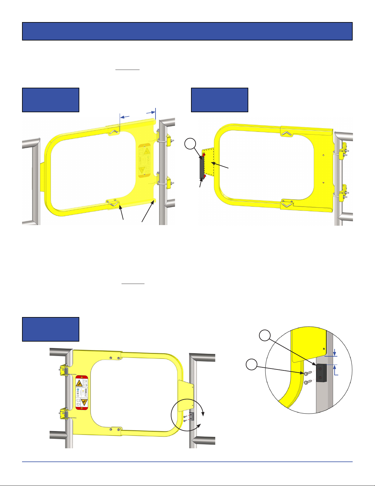
5
LSG Series
Rev042522
© 2022 PS Industries®Incorporated. All Rights Reserved.
Standard Round Installation
STEP 5. Position the Hoop within the adjustment range and ensure contact of the Strike Plate with the opposite
railing.
a. Tighten Vice Bolts to 10ft*lbs.
b. Install Strike Pad in a location where it protects contact between the Strike Plate and the railing.
CRITICAL VERIFY INSTALLATION
1. Strike fully overlaps stopping surface.
2. End of the Hoop is within the Hoop Adjustment Range illustrated.
3. Tighten Vice Bolts to 10 ft*lbs. Two (2) nuts per Vice Bolt.
4. Operate gate to ensure free movement.
STEP 6. Utilize provided self-drillers and fasten Strike Support Block to railing.
a. Install the Strike Support Block so it is 1/
4” below the Strike Plate.
Step 5
Illustration I
Step 5
Illustration II
HOOP ADJ.
RANGE
Strike Pad
Zone
Strike
Pad
CRITICAL END OF HOOP TUBE
MUST BE WITHIN THE HOOP
ADJ. RANGE ILLUSTRATED!
A
Step 6
Illustration I
DETAIL A
3.7
3.6
3.5
1/
4”
NOTICE Strike block to support 200 lbs downward OSHA loading.
6LSG Series
Rev042522
© 2022 PS Industries®Incorporated. All Rights Reserved.
Standard Round Installation
CRITICAL Installation of Strike Support Block is required for this product to meet the loading requirements of OSHA,
ANSI, and Canada OHS requirements when this product is used for fall protection.
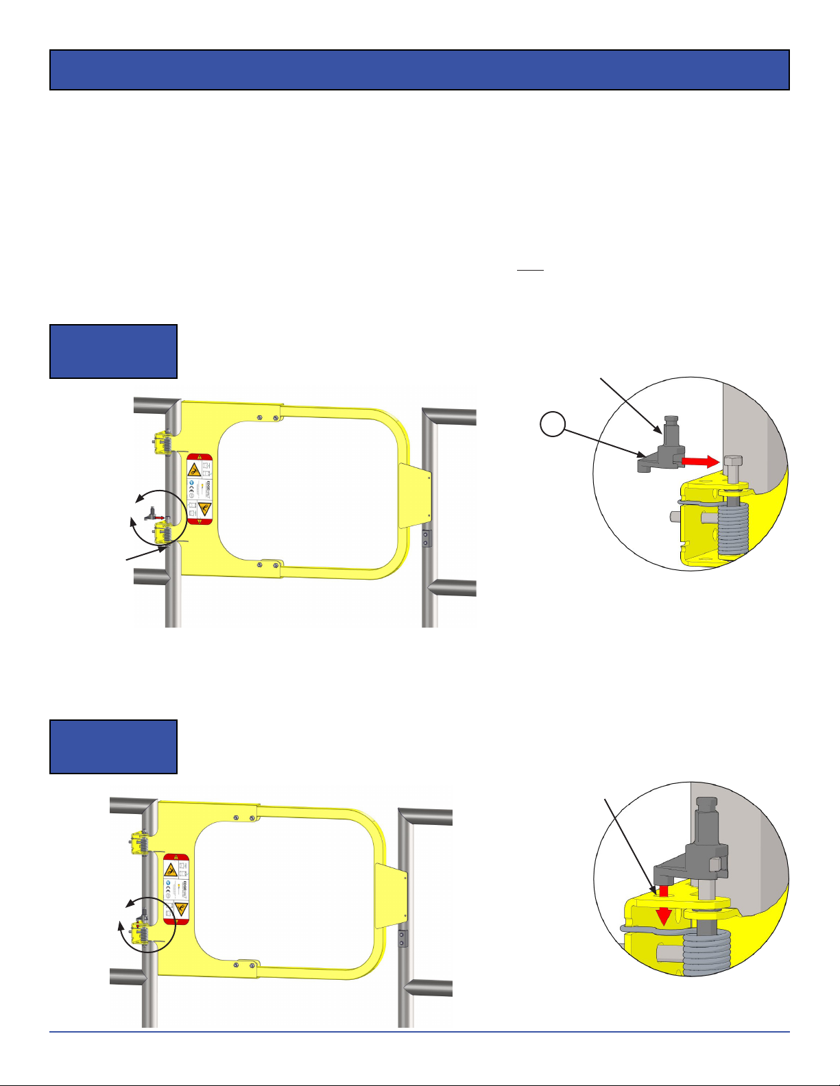
STEP 7. Installation of Slam-ProofTM Damper Kit is recommended, but it is not required. The Slam-ProofTM Damper
Kit controls the closing speed of the gate in order to eliminate slamming and noise.
NOTICE DAMPER IS NOT RECOMMENDED FOR USE BELOW 0○F.
NOTICE Damper can be installed in either orientation on either hinge location, as long as it is installed on the hex
head of the bolt (not the nut).
a. Slightly loosen hinge bolt on chosen hinge (top or bottom), do NOT remove nut.
b. Push hinge bolt up but not out of the hinge.
c. Slide Damper Stud onto the hex head of the bolt (not the nut). Refer to Detail B.
B
Step 7
Illustration I
DETAIL B
C
Step 7
Illustration II
DETAIL C
d. Align the Damper Stud with the receiving hole in the Hinge Bracket.
e. Push the Damper Stud ush with the Hinge Bracket (aligning the pin/hole). Refer to Detail C.
f. Carefully tighten the nut of the hinge bolt until the damper stud is in contact with the Hinge Bracket, and
add an additional half turn to the nut.
Receiving Hole in Hinge
Bracket to accept alignment
pin of Damper Stud
Damper Stud
Do NOT
remove Nut!
4.1
7
LSG Series
Rev042522
© 2022 PS Industries®Incorporated. All Rights Reserved.
CRITICAL Do not over-tighten hinge bolt. Over-tightening the hinge bolt will bend the Hinge Bracket tight around the
Hinge Plate bushings. If this occurs, loosen nut by a half twist to ensure the hinge pivots/operates freely.
g. Align the slot in the damper plate with the Hinge Plate edge and slide Damper down over the top of the
Damper Stud. If necessary, rotate the gate until all components align.
NOTICE Damper case is zinc plated steel and not recommended for long-term exposure to harsh or corrosive
chemicals or environments. It is the responsibility of the installer to determine if environmental conditions
are suitable for damper use.
h. Lastly, install the O-ring over the top of the Damper Stud to retain Damper in place.
D
Step 7
Illustration III
DETAIL D
Standard Round Installation
Damper
4.3
4.2
O-Ring
E
Step 8
Illustration I
Deeper Slot:
Slower Close
DETAIL E
Short Notch:
Faster Close
STEP 8. OPTIONAL ADJUSTMENT: Adjust Spring tension/action by choosing one of the two grooves in the back of the
hinge bracket and placing spring leg in slot.
a. Short notch is for more of “snappy” closing (faster with more force).
b. Deeper slot is for a slower closing force.
8LSG Series
Rev042522
© 2022 PS Industries®Incorporated. All Rights Reserved.
Installation on Angle Iron Railing
Align gate to the top of railing
TOP VIEW FRONT VIEW
Angle Iron
Railing
Match Drill
(one hole per bracket)
Step 1
Illustration I
Step 2
Illustration I
Step 3
Illustration I
Step 4
Illustration I
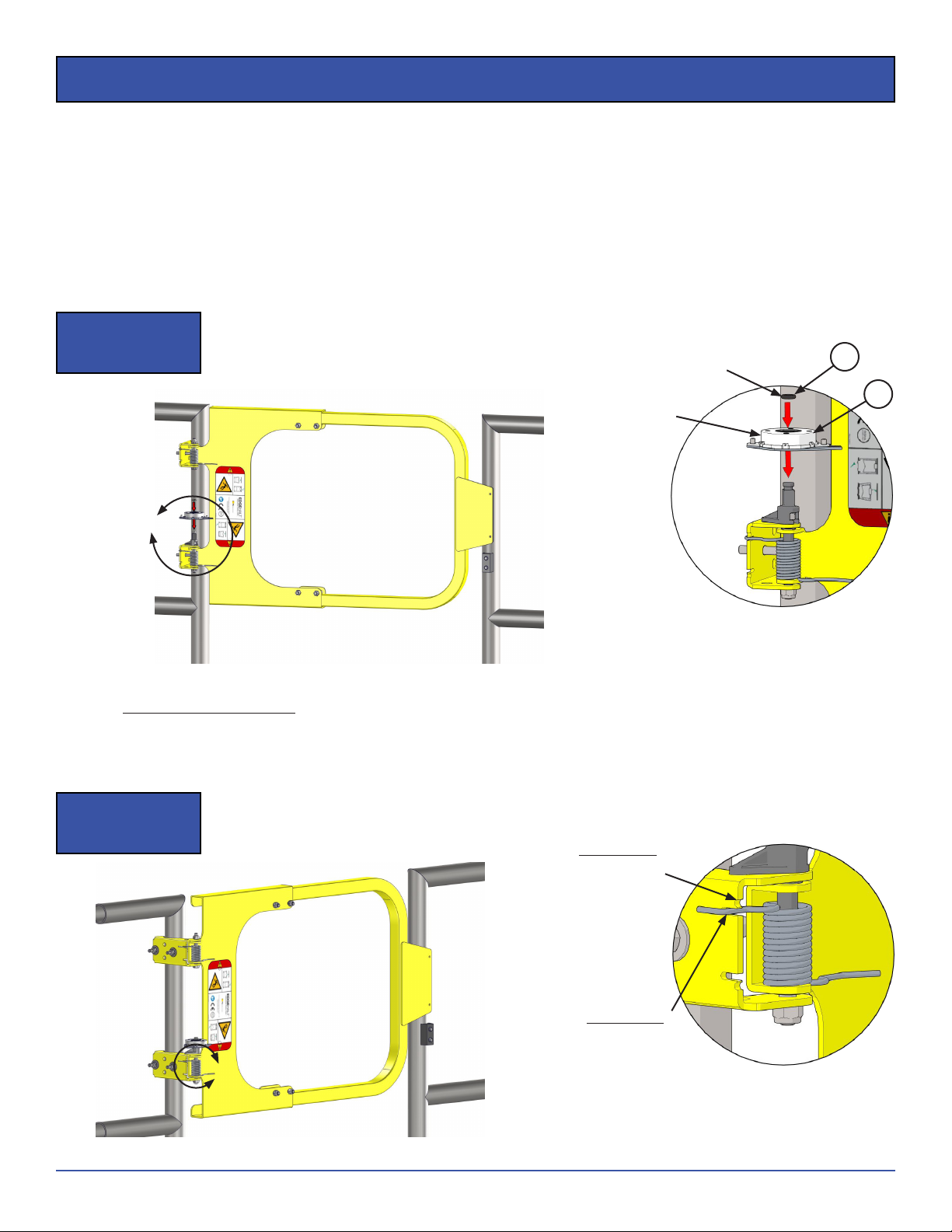
X. Installation on Angle Iron Railing (supplied by the Installer)
NOTICE If mounting your Ladder Safety Gate to angle iron railing: Gate bolts directly to existing railing (see below
installation instructions). If you do not wish to drill into your existing railing system, call PS Safety Access at
877.446.1519 to order a “no drill” adapter bracket.
STEP 1. Align the Ladder Safety Gate Railing Bracket to the inside of the angle iron.
STEP 2. Align top of Ladder Safety Gate to align with top of railing.
a. If no railing, adjust top of gate to 42” above walking surface.
STEP 3. Match drill 5/
16” holes into the railing (one (1) per Railing Bracket).
STEP 4. Insert appropriate mounting bolts through Railing Brackets into angle iron railing (mounting bolts provided
by the Installer).
a. Loosely attach the Ladder Safety Gate to the angle iron.
NOTICE Rest of Gate not shown.
STEP 5. Refer to STEPS 4-7 on Page 4 and 5 for remainder of installation
IMPORTANT! If no stop surface is available for the Strike Plate to rest against, install stop surface (Provided by the
Installer), using appropriate anchoring hardware and material, to align with the Strike Plate. Contact PS
Safety Access at 877.446.1519 to purchase the LSGPS Safety Gate Model as an alternate solution (which
does not require a Strike Plate or stop surface).
NOTICE Mounting bolts not included.
Recommended Hardware: Minimum 5/
16” grade 5 hex head
bolts of appropriate length with washers and self-locking
nuts.
1”
typ.

9
LSG Series
Rev042522
© 2022 PS Industries®Incorporated. All Rights Reserved.
Installation on Flat Bar Railing or Wall Surface
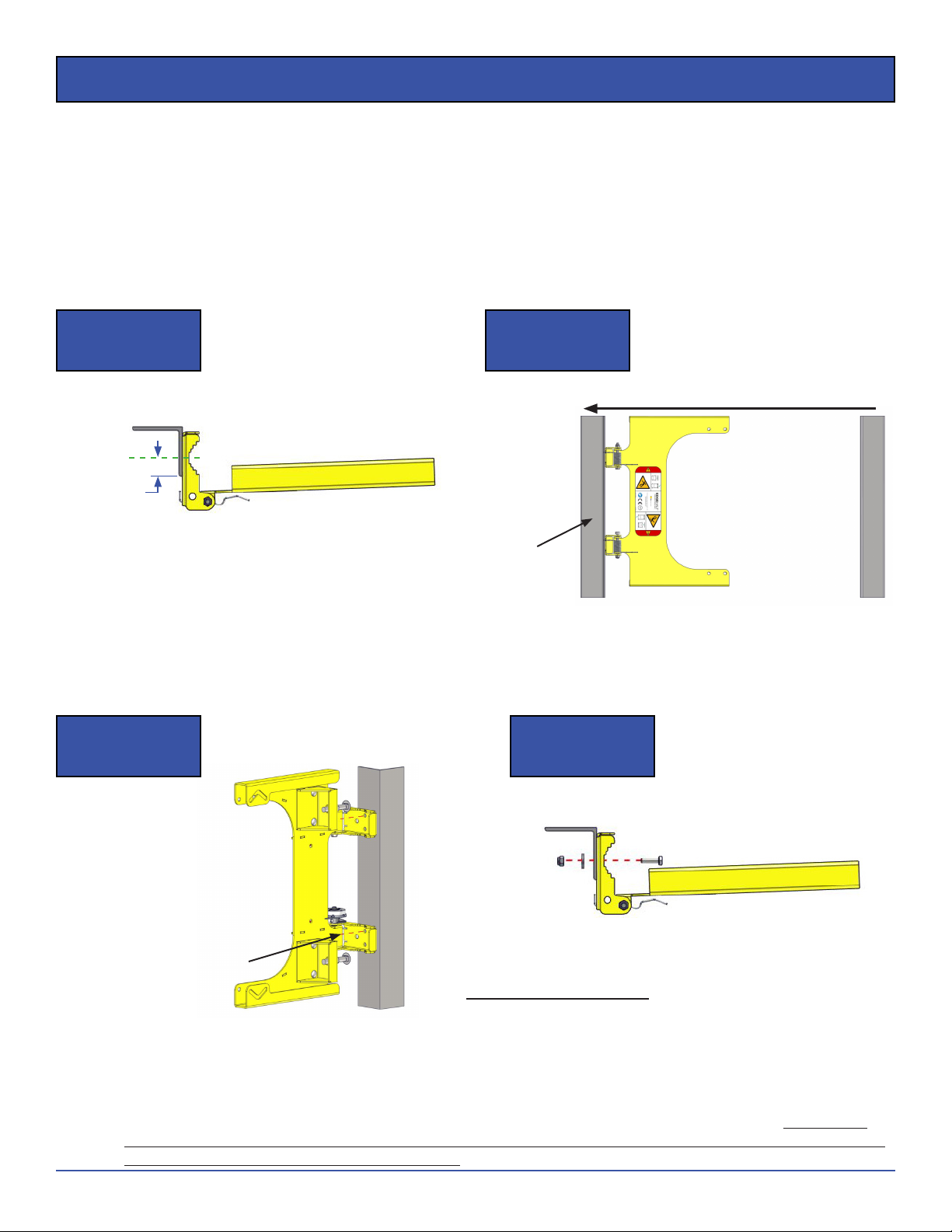
XI. Installation on Flat Bar Railing or Flat Wall Surface (supplied by the Installer)
NOTICE If mounting your Ladder Safety Gate to at bar railing: Gate bolts directly to existing railing (see below
installation instructions). If you do not wish to drill into your existing railing system, call PS Safety Access at
877.446.1519 to order a “no drill” adapter bracket.
STEP 1. Align the Ladder Safety Gate Railing Bracket ush to the at bar/at wall.
STEP 2. Align top of Ladder Safety Gate to align with top of railing.
a. If no railing, adjust top of gate to 42” above walking surface.
STEP 3. Match drill 3/
8” holes into the railing (one (1) per Railing Bracket).
STEP 4. Insert appropriate mounting bolts through Railing Brackets into at bar railing (mounting bolts provided by
the Installer).
NOTICE Rest of Gate not shown.
STEP 5. Refer to STEPS 4-7 on Page 4 and 5 for remainder of installation
IMPORTANT! If no stop surface is available for the Strike Plate to rest against, install stop surface (Provided by the
Installer), using appropriate anchoring hardware and material, to align with the Strike Plate. Contact PS
Safety Access at 877.446.1519 to purchase the LSGPS Safety Gate Model as an alternate solution (which
does not require a Strike Plate or stop surface).
NOTICE Mounting bolts not included.
Recommended Hardware for mounting to Flat Bar Railing:
Minimum 5/
16” grade 5 Hex head bolts of appropriate
length with washers and self-locking nuts.
Recommended Hardware for mounting to Flat Wall
Surface: Minimum use mechanical or chemical fastener,
sized appropriate, for mounting material and loading
requirements.
Align gate to the top of railing
TOP VIEW FRONT VIEW
Flat Bar or
Flat Wall
Step 1
Illustration I
Step 2
Illustration I
Step 3
Illustration I
Step 4
Illustration I
Match Drill
(one hole per bracket)
10 LSG Series
Rev042522
© 2022 PS Industries®Incorporated. All Rights Reserved.
Replacement Parts List
**For replacement springs, order Torsion Spring Kit
(part #511686.) Kit includes (1)LSG Torsion Spring,
(2)Bushings and Installation Instructions.
TO ORDER PARTS CONTACT PS SAFETY ACCESS AT
Gate Finish Type
ITEM # DESCRIPTION QTY PCY GAL 304SW
1 REFER TO HARDWARE VARIANT
1.1 LSG;HINGE BRACKET 2 515689 51574 2 515759
1.2 REFER TO HARDWARE VARIANT
1.3 LSG;TORSION SPRING, ST. STL 2 501659 501659 501659
1.4 BEARING;G300 FLANGE, .3125ID 4 509753 509753 509753
1.5 BOLT;HEX5/16”18X3 2 500431 500431 508239
1.6 NUT;NYLOCK 5/16”18 2 501126 501126 508995
1.7 DECAL;LSG ANSI DANGER 1 500569 500569 500569
2 REFER TO HARDWARE VARIANT
3 LSG;HARDWARE KIT 1 515845 515845 515846
3.1 BOLT;U 5/16”18X1 1/2 PIPE 2 500461 500461 515985
3.2 LSG;VICE BOLT 2 515623 515623 515624
3.3 NUT;NYLOCK 5/16”18 8 501126 501126 508995
3.4 WASHER;FLAT 5/16” 4 501949 501949 508053
3.5 LSG;STRIKE SUPPORT BLOCK PC 1 514493 514493 514493
3.6 SCREW;HEXDRILL 14X2 2 506020 506020 506072
3.7 LSG;BUMPER .25X1X5.75 PSA 1 514398 514398 514398
4 LSG;SLAM-PROOF KIT 1 515814 515814 515814
4.1 LSG;DAMPER STUD 1 515791 515791 515791
4.2 O-RING;DASH 203 BUNA-N 1 515790 515790 515790
4.3 LSG;DAMPER ASSEMBLY 1 515813 515813 515813
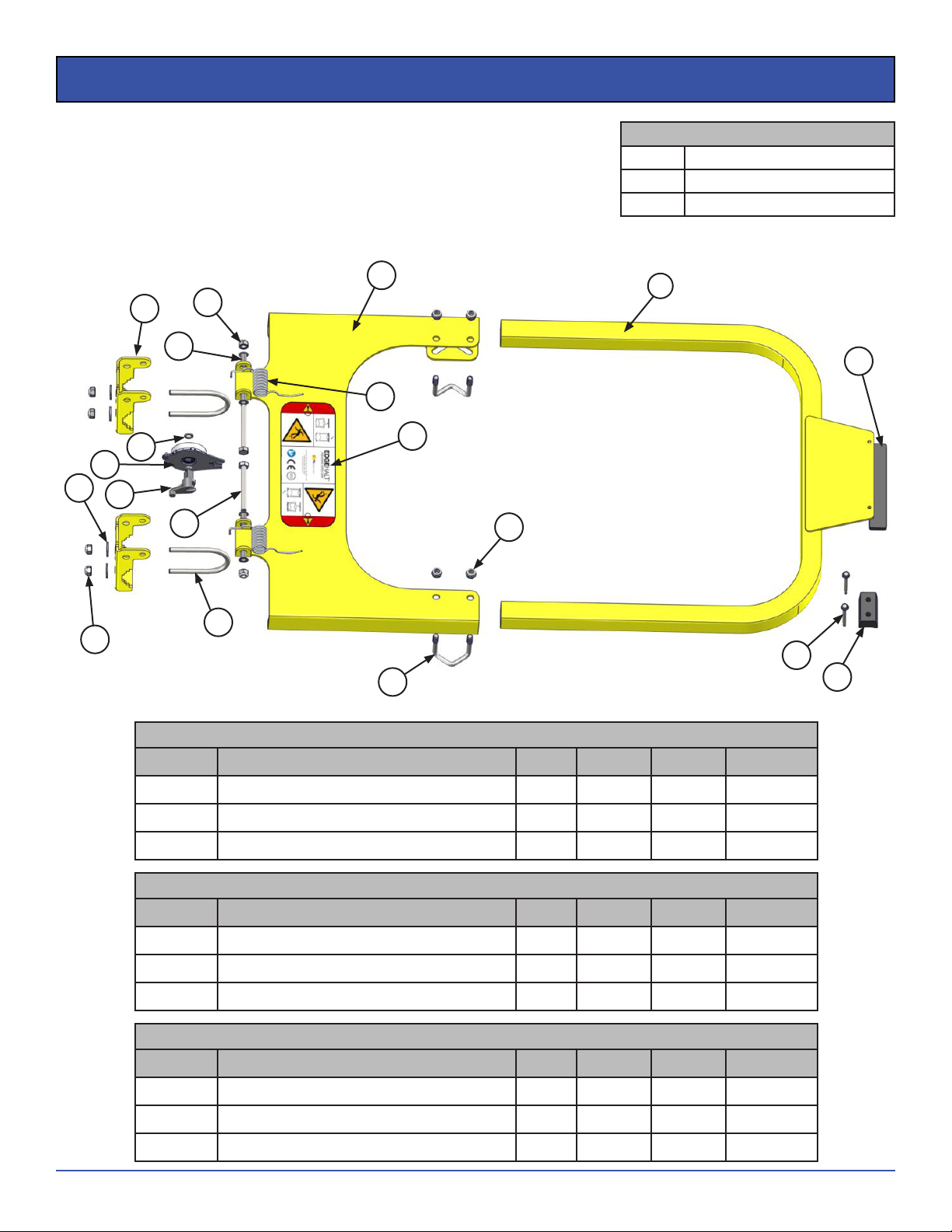
XII. Replacement Parts List
A. This Replacement Parts List are for all PCY/GAL/304SW Models.
B. Additional Hardware Variants and the Replacement Parts Diagram are located on Page 11.
FINISH OPTIONS
304SW 304 Stainless Steel Seal-Welded
PCY Powder Coat Safety Yellow
GAL Hot Dipped Galvanized
Hardware Variant for LSG-1520
ITEM # DESCRIPTION QTY PCY GAL 304SW
1 LSG;HINGE PLATE SM ASM 1 516011 516012 516015
1.2 LSG;HINGE PLATE 1 516009 516010 516014
2 LSG;HOOPWELD 1520 1 515989 515990 516003
11
LSG Series
Rev042522
© 2022 PS Industries®Incorporated. All Rights Reserved.
Replacement Parts Diagrams
XIII. Replacement Parts Diagrams
A. This Parts Diagram is for all PCY/GAL/304SW Models.
B. The Replacement Parts List is located on Page 10.
FINISH OPTIONS
304SW 304 Stainless Steel Seal-Welded
PCY Powder Coat Safety Yellow
GAL Hot Dipped Galvanized
3.1
3.2
3.3
3.3
3.4
1.1
1.2
1.5
1.4
1.6
1.7
1.3
2
3.5
3.6
3.7
4.1
4.3
4.2
Hardware Variant for LSG-2030
ITEM # DESCRIPTION QTY PCY GAL 304SW
1 LSG;HINGE PLATE ASM 1 515734 51574 3 515760
1.2 LSG;HINGE PLATE 1 515692 515692 515762
2 LSG;HOOPWELD 2030 1 515701 51574 9 516004
Hardware Variant for LSG-3040
ITEM # DESCRIPTION QTY PCY GAL 304SW
1 LSG;HINGE PLATE ASM 1 515734 51574 3 515760
1.2 LSG;HINGE PLATE 1 515692 515692 515762
2 LSG;HOOPWELD 3040 1 515705 515753 516005
Hardware Variant for LSG-4050
ITEM # DESCRIPTION QTY PCY GAL 304SW
1 LSG;HINGE PLATE ASM 1 515734 51574 3 515760
1.2 LSG;HINGE PLATE 1 515692 515692 515762
2 LSG;HOOPWELD 4050 1 515709 515757 516006

12 LSG Series
Rev042522
© 2022 PS Industries®Incorporated. All Rights Reserved.
Inspection and Maintenance
XIV. Inspection and Maintenance
A. Environmental conditions may affect the maintenance and repair requirements of the product, and
recommended preventative maintenance frequency.
B. If any of the inspection items are found to not meet the standard IMMEDIATELY “TAG OUT” the EdgeHalt®
Ladder Safety Gate from active use and guard the opening until repairs are completed.
NOTICE PS Safety Access recommends that the owner implement a regular and preventative maintenance program
to inspect and maintain Ladder Safety Gate at a minimum, in accordance with the recommendations in the
table below.
WARNING While performing maintenance and inspection ensure personnel utilize appropriate fall protection
equipment and procedures.
Recommended Preventative Maintenance
ITEM FREQUENCY ITEM DESCRIPTION WHAT TO INSPECT STANDARD REPAIR ACTION
1 Each Use General Housekeeping Opening Opening must be kept free of debris
and obstructions. Always keep area clean.
2 Weekly Gate Gate for corrosion or damage. To protect the structural integrity and
provide engineered safety protection.
Touch up nishes, or renish as
necessary.
Welds and all structural
components
Welds and structural components
are in undamaged condition and free
of dents, bends, cracks, crazing, and
corrosion.
Replace component immediately.
Gate alignment and free
movement.
Gate must move freely without any
interference; proper alignment with
catch and self-closes to the closed
position.
Adjust gate as necessary.
3 Monthly Gate Components Pivot Points (Bearings) for free
movement.
Must be free of all debris, corrosion,
and operates smoothly. Replace as necessary.
Location of Strike Must be hitting the right spot evenly. Adjust gate as necessary.
Springs Intact and Operating correctly. Replace as necessary.
Operation of Damper Must be free of all debris, corrosion,
and operates smoothly. Replace as necessary.
Damping Action
Gate soft closes, gate closes
completely. Remove damper if it
hinders operation. Damper is not
required for rated safety protection.
Slam-proof time will increase slightly
in very cold temperatures; this is
normal as damping action is affected
by temperature.
There are no damper adjustments,
replace if required.
4 Monthly Structural Attachment All Fasteners (Structural
Attachment)
Fasteners must be present and
be tightened to torque spec;
connections pulled into rm contact
by the fastener, no gaps between
material.
Tighten fasteners to torque spec.
Replace any missing fasteners.
5 Monthly Labels All labels Manufacturer's labels in place and
legible.
Replace. Contact manufacturer for
FREE replacement labels.
6After
Installation Installation Integrity Structural integrity of gate and
mounting structure.
Ensure product meets applicable
safety codes and loading
requirements.
Ensure all installation steps were
followed completely.

13
LSG Series
Rev042522
© 2022 PS Industries®Incorporated. All Rights Reserved.
Rev. 011822
PS INDUSTRIES® INCORPORATED – LIMITED WARRANTY
Limited Warranty: Subject to the terms of this Limited Warranty, PS Industries® Incorporated warrants to the original user or consumer (the
“Owner”) of a PS Industries product (the “Product”) that, for a period of one (1) year from date of shipment, the Product will be free from defects
in material and workmanship under normal use and service, and provided the Product is installed, operated and maintained in accordance with
instructions supplied by PS Industries. The terms and limitations of this Limited Warranty apply to all repaired or replacement Products for a term
equal to the balance of the warranty remaining on the Product that was repaired or replaced as of the date of such repair or replacement. Register
online at: www.psindustries.com/contact/register-your-product
PS Flood BarriersTM Product Warranty Registration: For PS Flood BarriersTM Products, this Limited Warranty will only be valid if the Owner
completes the Warranty Registration Form provided within thirty (30) days of Product installation. To request a copy of the Warranty Registration
Form, contact PS Industries Incorporated, 1150 S. 48th Street, Grand Forks, ND 58201, phone 877-446-1519, email: 4psinfo@psindustries.com.
Register online at: www.psindustries.com/contact/register-your-product/ Additional Warranty Registration Forms can be downloaded at
www.psfloodbarriers.com/download-center/
Warranty Exclusions: Notwithstanding anything to the contrary, this Limited Warranty does not cover any of the following:
1. Normal wear and tear (including, but not limited to, normal wear and tear to gaskets and weather seals); damage or accidents resulting
from freight damage, from failure to follow precautionary safety measures, or applied paint failure; abuse, misuse or unauthorized
modification of the Product; misapplication; improper installation; or any defects, damage or other harm that is not the result of the
acts or omissions of PS Industries.
2. Cost of field labor or other charges incurred by Owner in removing and/or re-affixing the Product or any part or component thereof.
3. Transportation costs.
Unauthorized modification of or to the Product voids this Limited Warranty. Authorized modifications, received in writing from PS Industries, as
long as the modification is accomplished in strict accordance with PS Industries’ instructions, does not void warranty. To request product
modifications contact PS Industries, 1150 S. 48th Street, Grand Forks, ND 58201, phone 877-446-1519, email: 4psinfo@psindustries.com.
Claim Procedure: To make a claim under this Limited Warranty, the claim must be received by PS Industries before the expiration of the above
stated Limited Warranty period together with proof of purchase. Contact PS Industries at the address shown below.
PS Industries Incorporated Toll Free: 877-446-1519
Attention: Warranty Phone: 701-746-4519
1150 S. 48th Street Fax: 701-746-8340
Grand Forks, ND 58201 E-mail: 4psinfo@psindustries.com
An authorized PS Industries representative must be given a reasonable opportunity to inspect and investigate the alleged Product defect prior to
any work being done that affects the Product or its installation. PS Industries reserves the right to charge reasonable amounts for travel and labor
associated with investigation of claims. PS Industries may also require photographs of the alleged Product defect or return of the Product or part
to a designated PS Industries location, freight prepaid. A return goods authorization must be received prior to the return of the Product or part.
Please contact PS Industries to determine the designated location for return and to obtain the return material authorization.
Exclusive Remedy: In the event of a warranty claim that PS Industries determines to be covered by this Limited Warranty, PS Industries will
replace or repair, at PS Industries’ discretion, the Product or any part of the Product found to be defective.
Disclaimers: The above warranty and remedy is the sole express warranty and remedy given by PS Industries on its Product. No warranties or
representations at any time made by any representative from PS Industries shall vary or expand the provisions hereof. TO THE EXTENT PERMITTED
BY LAW, ALL EXPRESS AND IMPLIED WARRANTIES (INCLUDING IMPLIED WARRANTIES OF MERCHANTABILITY, FITNESS FOR A PARTICULAR
PURPOSE AND NON-INFRINGEMENT) OTHER THAN THE EXPRESS LIMITED WARRANTY SET FORTH ABOVE ARE EXPRESSLY DISCLAIMED. UPON THE
EXPIRATION OF THE ABOVE STATED LIMITED WARRANTY PERIOD, ANY AND ALL APPLICABLE IMPLIED WARRANTIES, INCLUDING, WITHOUT
LIMITATION, WARRANTIES OF MERCHANTABILITY, FITNESS FOR A PARTICULAR PURPOSE AND NON-INFRINGEMENT, ARE DISCLAIMED. SOME
STATES DO NOT ALLOW LIMITATION ON HOW LONG AN IMPLIED WARRANTY LASTS, SO THE ABOVE LIMITATION MAY NOT APPLY TO OWNER.
LIABILITY LIMITATION: In no event will PS Industries’ liability to Owner or any other person or entity exceed the price paid to PS Industries for
the defective Product. IN NO EVENT SHALL PS INDUSTRIES BE LIABLE TO OWNER OR ANY OTHER PERSON OR ENTITY FOR INCIDENTAL,
CONSEQUENTIAL, INDIRECT OR SPECIAL DAMAGES OF ANY DESCRIPTION, WHETHER ARISING OUT OF WARRANTY (INCLUDING ANY IMPLIED
WARRANTIES) OR ANY OTHER CONTRACT, STRICT LIABILITY, NEGLIGENCE OR OTHER TORT, OR OTHERWISE, INCLUDING ARISING FROM
INSPECTION OR REMEDY DELAYS. SOME STATES DO NOT ALLOW THE EXCLUSION OR LIMITATION OF INCIDENTAL OR CONSEQUENTIAL DAMAGES,
SO THE ABOVE LIMITATION AND EXCLUSION MAY NOT APPLY TO OWNER.
THIS WARRANTY GIVES OWNER SPECIFIC LEGAL RIGHTS AND OWNER MAY ALSO HAVE OTHER RIGHTS, WHICH VARY FROM STATE TO STATE.

877.446.1519
1150 South 48th Street | Grand Forks, ND 58201
Product Registration:
psindustries.com/contact/register-your-product
This manual suits for next models
3
Table of contents
Other PS Industries Safety Equipment manuals


