PSA Products H.264 User manual

Network Digital Video Recorder
H.264
User manual
Please read instructions thoroughly before operation and retail it
for future reference.
V0.3

Notes:
! Do not place objects on this device!
! Do not let any solid or liquid enter the DVR!
! Clean the circuit board, connectors, fans and case with a brush regularly
but remember to turn off the power and pull the plug before cleaning .
! Do not disassemble, maintain the device, or replace parts by yourself.
! Avoid knocking this DVR. Do not drop the device.
Operational Environment
! Place and use the product at a temperature of 0 ℃~ 40 ℃. Avoid direct
sunlight and be away from heat sources.
! Do not install the device in a damp environment;
! Do not expose the device to smoky and dusty environment.
! Keep the device be installed horizontal and in a stable place. Take care to
prevent it from falling.

Directory
1 Production Introduction
1.1 Product overview ..................................................................................................... 1
1.2 Main functions ...................................................................................................... 1
2 Open-package check and cable connections
2.1 Open-package check............................................................................................... 1
2.2 Remote control......................................................................................................... 1
3 Basic operation
3.1 Turn on...................................................................................................................... 2
3.2 System login............................................................................................................ 2
3.3 Preview..................................................................................................................... 2
3.4 Desktop shortcut menu............................................................................................ 2
3.4.1 Circulation........................................................................................................ 3
3.4.2 Color setting..................................................................................................... 3
3.4.3 E- zoom........................................................................................................... 3
3.4.4 Audio................................................................................................................ 3
3.4.5 PTZ control............................................................................................................... 3
3.4.6 Playback.......................................................................................................... 4
4 Main menu
4.1 Main menu navigation.............................................................................................. 5
4.2 Conguration management..................................................................................... 6
4.2.1 Basic conguration.......................................................................................... 6
4.2.2 Live conguration............................................................................................ 7
4.2.3 Video conguration.......................................................................................... 8
4.2.4 Video program................................................................................................. 12
4.2.5 Alarm................................................................................................................ 13
4.2.6 Network............................................................................................................ 16
4.2.7 User management.......................................................................................... 19
4.2.8 P.T.Z ................................................................................................................ 20
4.2.9 Advanced conguration.................................................................................. 23
4.3 Data retrieval............................................................................................................ 23
4.3.1Time search...................................................................................................... 23
4.3.2 Event search................................................................................................... 24
4.3.3 File management............................................................................................ 24
4.3.4 Image............................................................................................................... 24
4.4 Info............................................................................................................................ 25
4.5 View Infor.................................................................................................................. 26
4.5.1 System Info..................................................................................................... 27
4.5.2 Event Info........................................................................................................ 27
4.5.3 System log..................................................................................................... . 27
4.5.4 Network state................................................................................................. 28
4.5.5 Online users................................................................................................... 28
4.6 Disk management................................................................................................... 28

4.7 upgrade maintenance............................................................................................. 28
4.8 Logout..................................................................................................................... 29
4.9 System shutdown.................................................................................................... 29
5 Remote monitoring
5.1 Access..................................................................................................................... 29
5.1.1 LAN................................................................................................................ 29
5.1.2WAN................................................................................................................ 31
5.2 Remote eld preview.............................................................................................. 32
Appendix 1. FAQ....................................................................................................... 33
Appendix 2. Hard disk capability calculation............................................... 38

1
1 Production Introduction
1.1 Product overview
The series DVR is designed specially for security and defence eld and is an outstanding
digital surveillance product. It introduces embedded LINUX operating system which is very
stable. It introduces standard H.264 mp video compressed format and unique temporal
and spatial filtering algorithm which insures the high quality image and low bit rate
synchronous audio and video surveillance. It introduces TCP/IP network technology which
achieves the strong network data transmission capability and remote control capability.
The series DVR can be used individually or online applied as a part of a safety surveillance
network. With the professional network video surveillance software it achieves the strong
network communication ability and telecommunication ability.
The series DVR can be applied in the bank, telecom, electric power system, judicial system,
transportation, intelligent housing, factory, storehouse, water conservancy and so on.
2 Open-package check and cable connections
2.1 Open-package check
When you receive the product, please conrm whether it is consistent with the product
model you ordered and check carefully whether there is any obvious damage of the
product. After opening the casing, check whether the connection between the internal
data wire, power wire, fan power wire and so on and the main board are rm .Please
protect the labels afxed to the oor or rear panel , which is very important to our after-
sales service work. When you contact our company for after-sales service, we need you to
provide the model and serial No. on the label.
2.2 Remote controller operation
The operating steps to control multiple DVRs by remote control:
The default device number of the DVR is zero, you can operate directly without resetting
when using the remote controller to control a single DVR.. But if you use one remote
control to operate multiple DVRs, please refer to the following steps.
Step one: Enter DVR to see the device number: [System configuration]-[Basic
conguration]-[Device Number]. The device number of different DVR can be set the same.
For easy operation, we suggest to set the device number not too large.
Step two: Activate the remote control: Aim the remote control to the DVR you will control,
press the “ADD” button, then input the device number [between 1-65535], and then press
“ENTER” to conrm.
Step three: Cancel the remote control : You can lock the DVR when you press any button
with “ADD” button, or do no action on the buttons, it will be locked after 30 seconds.
2
3. Basic Operation
3.1 Turn on
Plug the power supply, the power indicator light will illuminate and the video recorder
turns on, you will hear a beep at this time. After startup, the default setting of the system is
multiple-screen output mode and video recording starting up automatically.
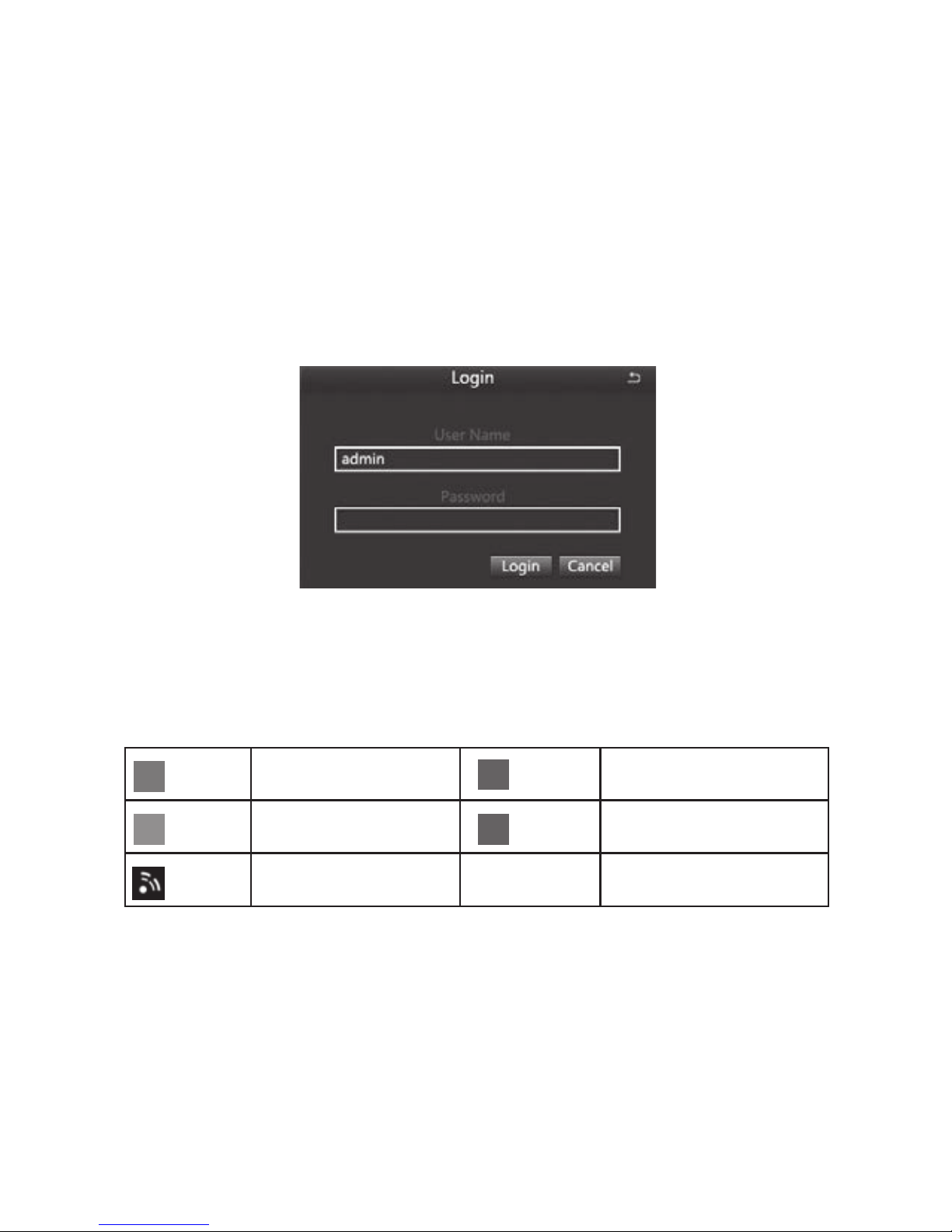
3.2 System login
When the DVR boots up, the user must login and the system provides the corresponding
functions with the user purview.
3.3 Preview
After entering the preview status , double-click the left mouse button to choose the switch
between the windows.
The system date, time and channel name are shown in each viewing window. The
surveillance video and the alarm status are shown in each window.
Table 3.1 Preview page icon
3.4 Desktop shortcut menu
In preview mode you can right click mouse to get a desktop shortcut menu and right
click mouse again to ESC the desktop shortcut menu.
Manual recording or
Trigger recording
Motion detection
recording
Network disconnection
(Green)
(Yellow)
(Red)
(Blue)
Alarm recording
Timing recording

3
Picture 3.2 Shortcut Menu
3.4.1 Start Scan
Start Scan means the system will show each live picture in order automatically according
to the order of the video devices in the channel grouping.
Only when the user selects the channel grouping under the display mode[main
menu]>[conguration management]>[live], and it can not show all channels completely
under the current preview, this button is available.
3.4.2 Colour
Set image parameters for all channels. The image parameters include: brightness,
contrast, saturation and hue.
3.4.3 E -Zoom
E-Zoom for big picture of single channel
3.4.4 Audio
Set startup, turn-off and silent mode of audio for the channel, and adjust the volume ..After
select (automatic), it will start up audio of the big picture channel automatically.
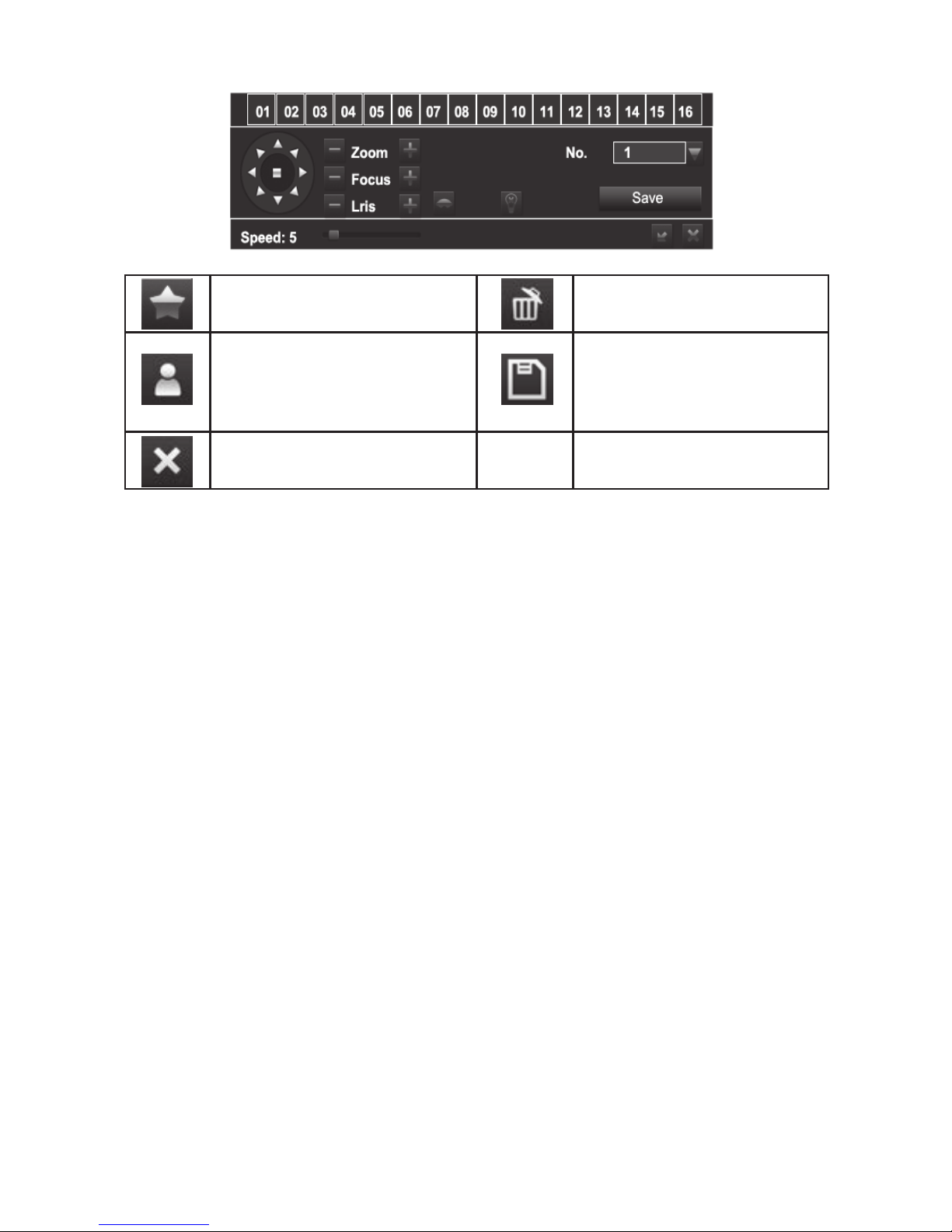
3.4.5 PTZ
Control the RS485 device of all channels. It can set address, Baud rate, Protocol, Preset,
trail patrol , track and so on of the RS485 device under [Main menu]>[Configuration
Management]>[PTZ].
Adjust direction
of the PTZ.
Wiper control.
Control the external infrared devices. Function hidden bar, right-click to cancel hidden.

4
3.4.6 Playback
Play the video les in the hard disk. You can also search the video according to time and
event under [main menu] →[data retrieval]to enter the playback interface.
(1)Playback control (2)Channel audio switch (3)function Hidden key (4)Operate playback
Playback control details as follow:
Table 3.2 Playback control key
Note: Frame by frame play back is achieved using the pause function.
Function
Play/Pause
Fast motion play
Play previous le
Single-screen display
Function
Play according to frame
Playback
Play next le
Multi-screen display
Button Button

5
4 Main menu
4.1 Main menu navigation
Set the system time, date format, time format, language, the
device number, video format, standby time, daylight saving time
Set the channel name, output mode, block area of each channel,
etc
Start up video recording , set up the video stream, position of
channel name, video circulation, snapshot, etc
Set timer recording, motion alarm recording, period of sensor
alarm recording
Set sensor alarm of each channel, motion detection, video loss,
other alarms, alarm output, etc
Set basic network parameters, and set network sub-stream,
email, WIFI and Dynamic Domain Name Service
Modify users, change passwords, add users and delete users
Set the PTZ address, baud rate, protocol, preset, cruise , track, etc.
Restore the factory settings, import and export the device
parameters
Search specied period of time recording , playback the video of
this period
Search motion detection, sensor alarm and all videos, play back
the video of this period
Inquiry and export of motion detection, video loss, sensor alarm
and other events
Search equipment operation log according to time, it can also be
exported
Display information of network settings and dynamic DNS
settings
Show hard disk’s total space, free space, read and write status
and to format. the hard disk
Delete and lock the video les of specied time period
Delete, lock and save the image of specied time period
Display the device name, serial number, version, release date
Display the current network users accessing the device
Upgraded with an external device ( eg: USB)
After log-off , exit system and log in
Main menu Submenu Function
Basic
conguration
Live
conguration
Recording
conguration
Recording
Plan
Alarm
conguration
Network
conguration
User
management
Advanced
conguration
Network
status
Hard disk
management
User log-off
Data retrieval
View
information
Time search
Event search
System Info
Event Info
System log
Online users
Image
P.T.Z
File management
Conguration
management
Upgrade
maintenance
System
shutdown
6
4.2 Conguration Management
Set every function parameters for the device, including: basic configuration, live
conguration, recording conguration, recording plan, alarm conguration, network
conguration, user management, PTZ conguration, advanced conguration
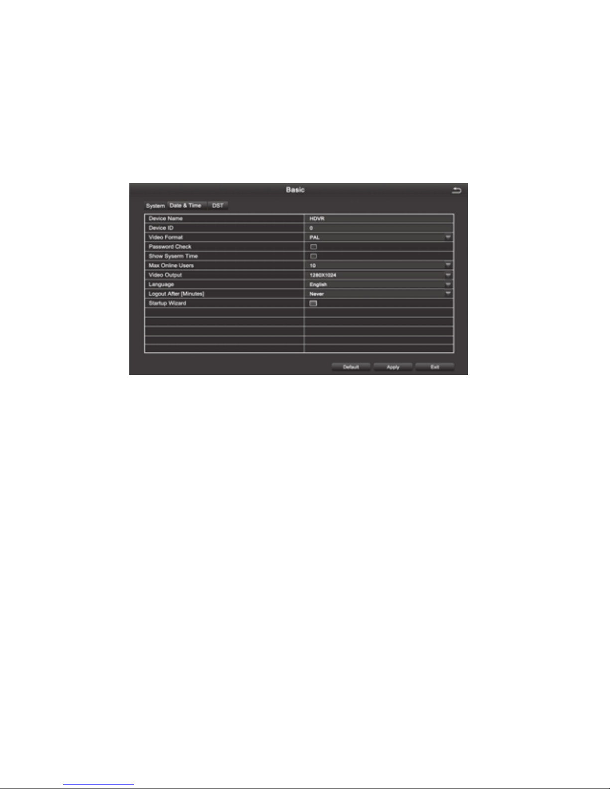
4.2.1 Basic Conguration
Basic conguration includes three sub menus: system, date and time, daylight saving time
Figure 4.10 Basic settings
1.The system
[Device Name] Client or system name displayed by IVSS
[Device ID] used when a remote control controls multiple DVR
[Video Format] Support PAL and NTSC format
[Password Check] Choosing this item means user must enter user name and password in
the system Settings, and have corresponding purview before corresponding operations
[Show System Time] Choose whether to display time in the eld or not
[Max Online Users] Set the number of network users visiting the device
[Video Output] User can select VGA 800 * 600, VGA 1024 * 768, VGA 1280 * 1024, HDMI,
etc. output mode
[Logout After (Minutes)] When there is no action exceeding the set time, the system will
automatically log out
[Startup Wizard ] Whether to display wizard or not when turn on the machine
2.Date & Time
In this interface, set the date format, time format, time zone; you can also adjust the
system time manually
Note: the default time zone of the system is GMT
You can select [Time Synchronization] to correct time. Network time server can be set
3.DST(Day Light Saving)
Set the start and end time of daylight saving time by week or date. As Figure 4.11,
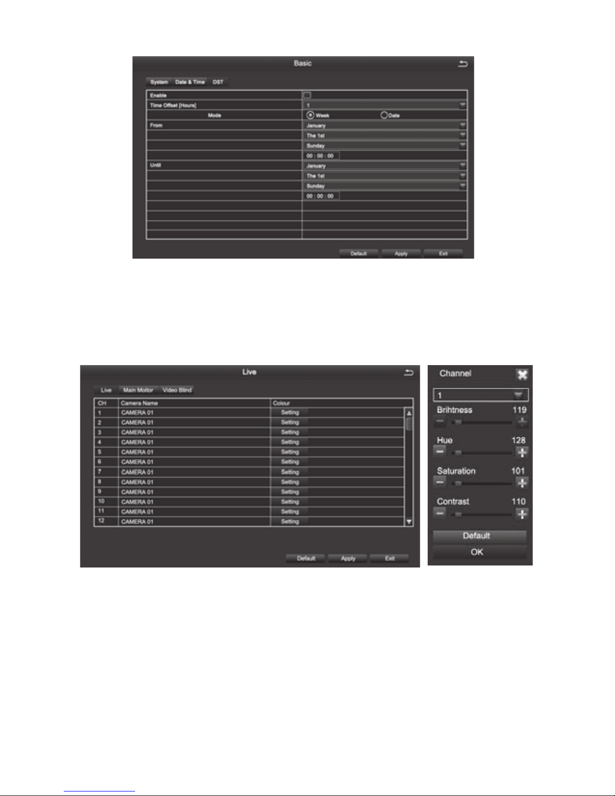
7
Daylight saving time setting Figure 4.11
4.2.2 Live Conguration
Live conguration includes three submenu: Live, Main Monitor, Video Blind.
1.Live
[Camera Name] Click channel Name, the system will pop up a soft keyboard, users can
change the channel name if necessary. Clicking the “shift “ key to switch input methods
[Colour] Users can adjust the brightness, hue, saturation, and contrast of the
corresponding channel
8
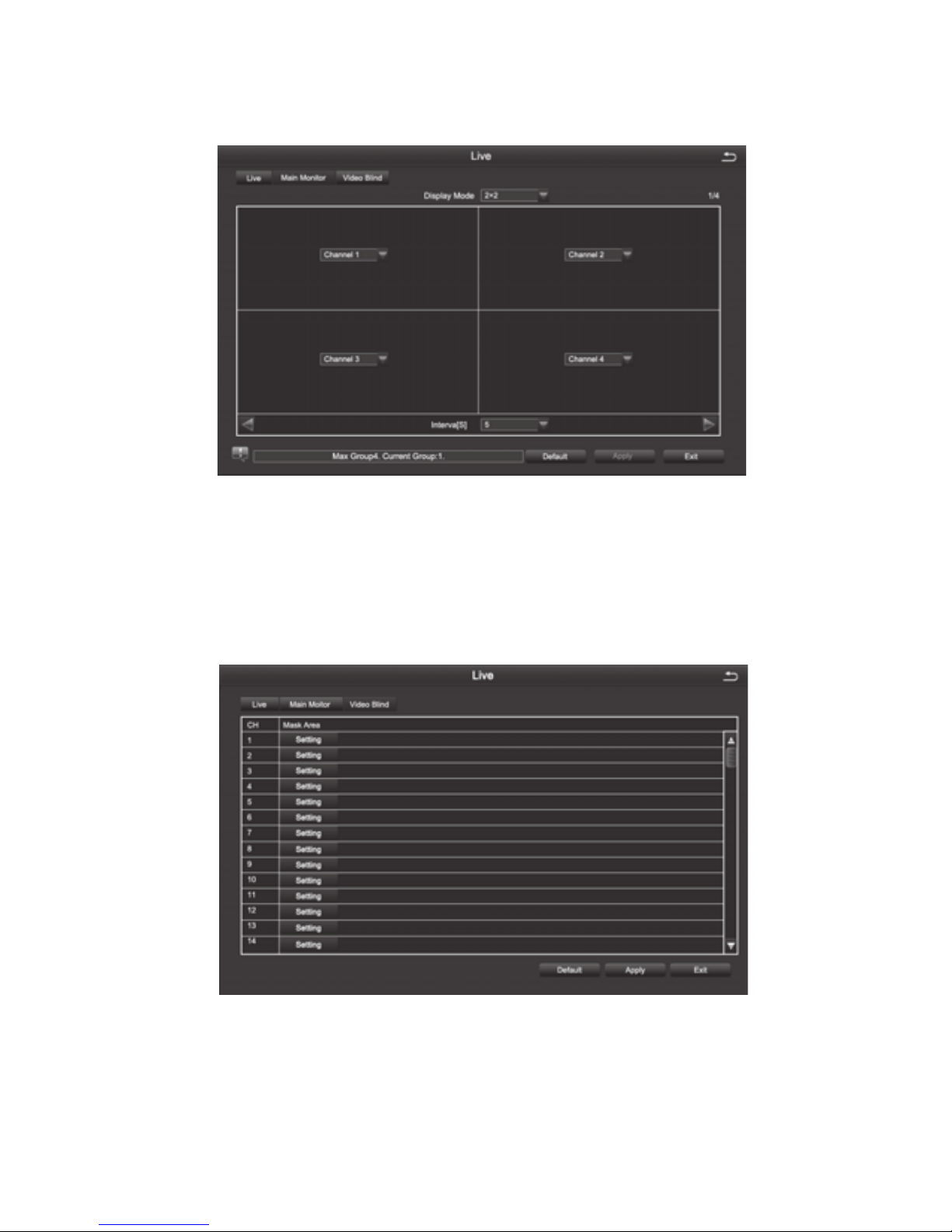
2. Main Monitor
[Interval] The time interval between one channel picture and the next one channel
3. Video Blind
Users can cover up some areas of the live picture, maximum of four areas per channel
[Setting] After entering the live picture , press and hold the left mouse button, drag the
mouse to set the blocked area , then click [apply]to save the settings; Double-click on the
area you want to delete, later changed into a black area, right-click, Exit. then click [apply]
can delete the blocked area
9
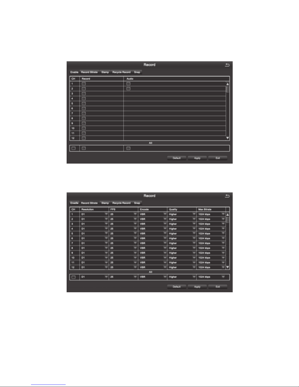
4.2.3 Recording Conguration.
Record configuration includes six submenus: Enable,Record Bitrate,Stamp,Recycle
Record,Snap
1. Enable
2. Record Bitrate
Note: Detailed parameters, to prevail in kind.
[Resolution] 4 channel device supports 4-CH D1; 8 channel device supports 8-CH D1; 16
channel device supports 16-CH D1.
[FPS] Range of choice : 1-30[NTSC] 1-25 (PAL)
[Encode] Support VBR and CBR
[Quality] The higher the quality is, the clearer the video images are
Optional quality levels: Lowest, Lower, Low, Medium, Higher, Highest
[Max Bitrate] Range of Choice : 256kbps~2048kbps
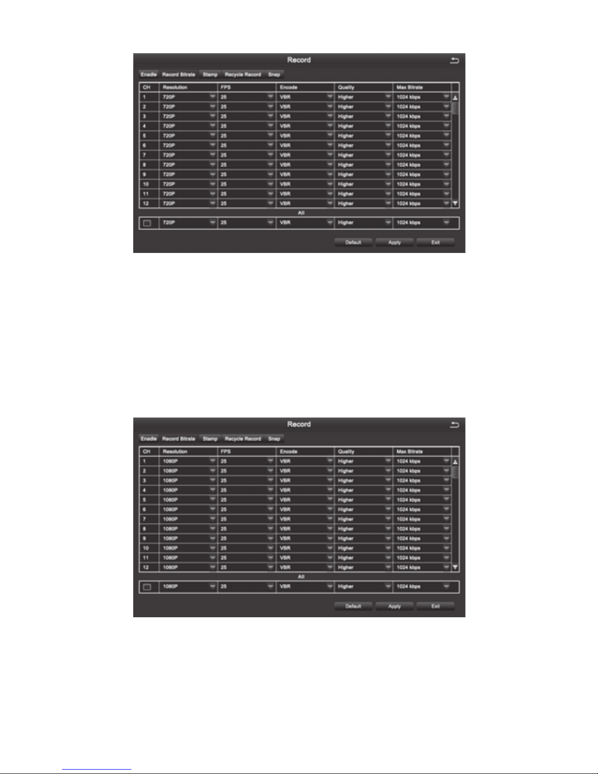
10
[Resolution] 4CH device supports both 4CH 720P (AHD Camera) and 4CH 960H(Analog
Camera); 8CH device supports both 8CH 720P(AHD Camera) and 8CH 960H(Analog
Camera).
[FPS] Range of choice : 1-30[NTSC] 1-25 (PAL)
[Encode] Support VBR and CBR
[Quality] The higher the quality is, the clearer the video images are
Optional quality levels: Lowest, Lower, Low, Medium, Higher, Highest
[Max Bitrate] Range of Choice : 256kbps~2048kbps
[Resolution] 4CH device supports both 4CH 1080P (AHD Camera) and 4CH 960H(Analog
Camera); 8CH device supports both 8CH 1080P(AHD Camera) and 8CH 960H(Analog
Camera).
[FPS] Range of choice : 1-30[NTSC] 1-25 (PAL)
[Encode] Support VBR and CBR

11
[Quality] The higher the quality is, the clearer the video images are
Optional quality levels: Lowest, Lower, Low, Medium, Higher, Highest
[Max Bitrate] Range of Choice : 256kbps~2048kbps
3. Stamp
[Camera Name] Choose whether to display the channel name or not
[Time Stamp] Choose whether to display time on this channel or not
[Position] After clicking this button, Users can use mouse to drag the channel name and
time stamp to any position on the live image
4. Recycle Record
After selecting this item , When the hard disk is full, it will automatically cover the earliest
les and continue recording ; Otherwise, it will automatically stop recording and prompt
"The remaining space is insufcient" on the screen
5. Snap
In this interface, the user can set the resolution, image quality level, time interval of
snapshot and the number of snapshot for one time
12
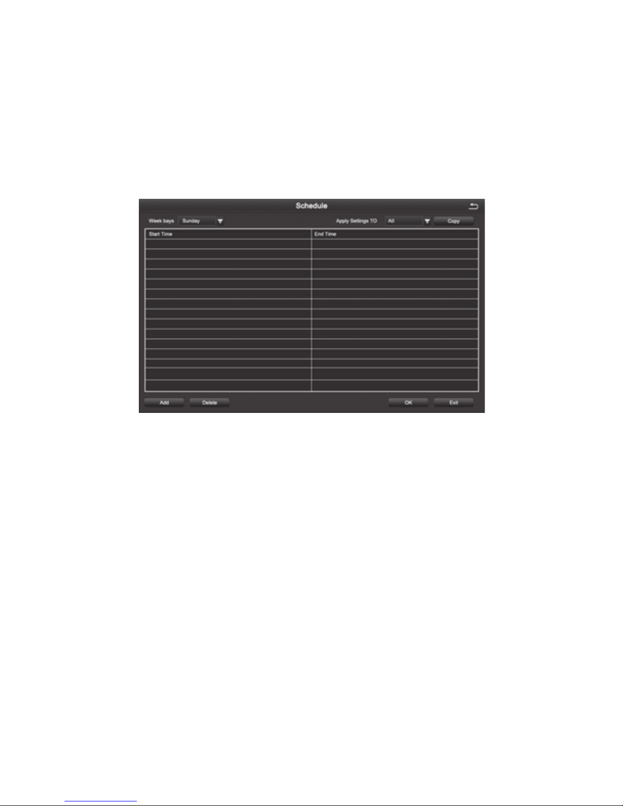
4.2.4 Schedule
Schedule includes three submenus: timing recording, motion alarm recording, and sensor
alarm recording
1. Timing Recording
[Copy] Apply the schedule of a channel to the other or all channels
Select the channel: Double click the left mouse button, edit the week plan, as shown in the
picture.
[Add] To add a recording schedule of some day
[Delete] To delete the selected schedule
[Copy] Copy the schedule of a specied date to another date.
2. Motion Alarm Recording
The setting method is the same to the timing recording setting, please refer to the timing
recording settings
Note: The default Schedule for Motion alarm is all selected
3. Sensor Alarm Recording
The setting method is the same to the timing recording setting, please refer to the timing
recording settings
Note: The default schedule for sensor alarm is all selected

13
4.2.5 Alarm Conguration
Alarm conguration includes ve submenus: Sensor alarm, motion detection, video loss,
other alarm and alarm output
1. Sensor
1-1 Basic
[Enable] To open sensor alarm function of the corresponding channels
[Type] To choose alarm type: Normally open and normally closed
[Name] Set the alarm name.
1-2 Alarm Handling
[Holding Time] To select alarm delay time for the channel , optional time: 5 s, 10 s, 20 s, 30 s,
60 s 120 s, always
[Trigger] After clicking you can set alarm Configuration, trigger recording, PTZ
linkage, etc
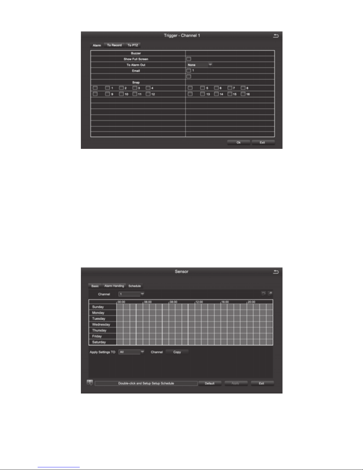
14
[Buzzer] After selecting the alarm, when an alarm is triggered , the buzzer will alarm
[Show Full Screen] When an alarm is triggered, the alarm channel screen will activate
[To Alarm Out] Select this item, it will trigger an alarm on the specied alarm output
[Email] When an alarm is triggered, the system will send the relevant information to the
user-specied mailbox, such as alarm event, snapshot, device name, device number, etc.
[Snap] When an alarm is triggered, the system will automatically capture the images of the
selected channel and store them to the hard disk.
[To PTZ] To set the action type and serial number of the linkage
1-3, Schedule
The method of setting the schedule of sensor alarm is the same to timing recording. For
the detailed setting steps , pls refer to 4.2.4 [Recording Schedule] [Timing Recording]
Note: The default schedule for sensor alarm is all selected
15
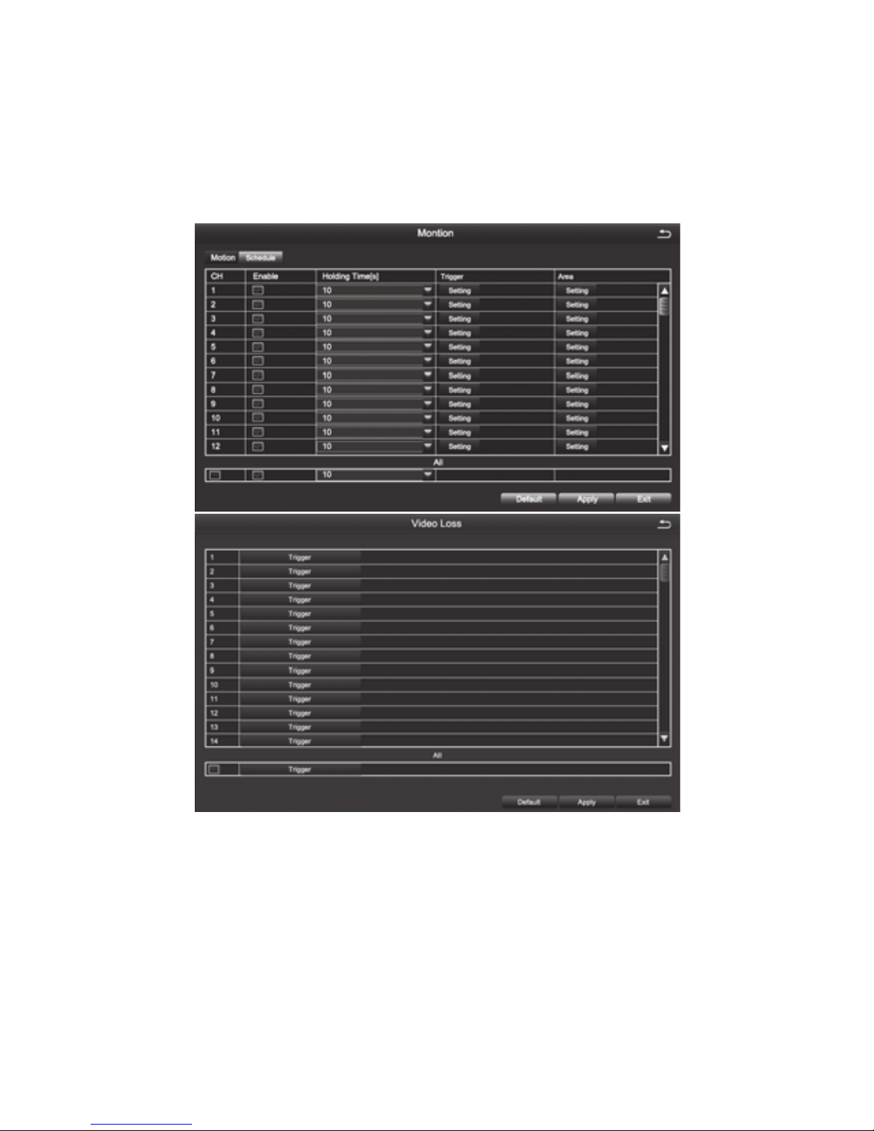
2. Motion Detection
Motion detection includes two submenus: motion detection and schedule
2-1, Motion Detection
By analyzing the video image, when the system detects a mobile signal which reaches a
preset sensitivity, motion detection alarm and the linkage function are initiated
[Enable] After selected, the motion detection function of the corresponding channel will be
opened.
[Holding Time] To select alarm delay time of the channel .Optional time:
5/10/20/30/60/120s always
[Trigger] The setting method is the same to that of sensor alarm, pls refer to 4.2.5
[Alarm Conguration], [Sensor Alarm Processing]
[Area] In this interface, the user can drag the scrollbar to adjust the sensitivity value (1-
8). The default value is 6, the smaller the value is, the higher the sensitivity is. Since the
sensitivity is affected by the color, time (day or night) and etc, so the user should adjust the
value according to the actual situation.
16
2-2, Recording Schedule
The setting of Motion Detection Schedule is the same to that of Timing Recording, For the
detailed steps please refer to 4.2.4 - [Recording Schedule] [Timing Recording].
Note: The default schedule of motion detection is all selected
3.Video Loss
The setting of video loss alarm processing is the same to that of sensor alarm processing.
For the detailed steps, please refer to 4.2.5 [Alarm Configuration] [Sensor Alarm
Processing]
4.Other Alarm
[Alarm Type] Including hard disk full, network address conflict, disconnection, HDD
attenuation warning and disk loss
[Buzzer ] When an alarm occurs, the device will emit "didi" two long beeps
[Email] When an alarm is triggered, the system will send the relevant information to the
user-specied mailbox, such as alarm events, snapshot, device name, device number, etc.
[To Alarm Out] To select this item, it will trigger an alarm on the specied alarm output
[Disk Shortage Alarm] When the remaining capacity of the disk reaches the set value, an
alarm will be triggered
4.2.6 Network Conguration
Network Conguration includes ve submenus: Network, Sub-Stream, Email, WiFi Setup,
DDNS
Set all areas to be
detection area
Clear the set
detection areas
Exit
Drag the mouse to test
whether the sensitivity value
and the detection area are
appropriate or not
Save the settings
Table of contents
Popular Network Hardware manuals by other brands


Turin Networks
Turin Networks TransAccess 155 quick start guide

Zte
Zte ZXA10 C300 Maintenance manual

Lütze
Lütze TLM-10 operating instructions

Matrix Switch Corporation
Matrix Switch Corporation MSC-HD121AAS product manual

Airaya
Airaya AI108-4958-N Manual and installation guide

LaCie
LaCie d2 Network 2 user manual