PT W1605 User manual

LIMITED WARRANTY
PERFORMANCE TOOL extends only the following warranties, and only to original retail purchasers. These warranties give
specific legal rights. Except where prohibited by local law, the law of the State of Washington governs all warranties and all
exclusions and limitations of warranties and remedies. There may be other rights which vary from state to state.
PERFORMANCE TOOL warrants the product to be free from defects in materials and workmanship under normal use and
service. A defective product may be returned for a free replacement within 90 days from the date of purchase, provided that
product is returned to place of purchase immediately after discovery of defect. After 90 days and up to 1 year from date of
purchase, PERFORMANCE TOOL will replace at no charge any parts which our examination shall disclose to be defective and
under warranty. These warranties shall be valid only when a sales receipt showing the date of purchase accompanies the
defective product or defective part(s) being returned. For part(s) after 90 days, please remit your request, postage prepaid to:
PERFORMANCE TOOL, P.O. Box 88259 Tukwila, WA 98138
These warranties exclude blades, bits, punches, dies, bulbs, fuses, and other consumables which must be replaced under
normal use and service. These warranties shall not apply to any product or part which is used for a purpose for which it is not
designed, or which has been repaired or altered in any way so as to affect adversely its performance or reliability, nor shall these
warranties apply to any product or part which has been subject to misuse, neglect, accident or wear and tear incident to normal
use and service.
PERFORMANCE TOOL does not authorize any other person to make any warranty or to assume any liability in connection with
its products.
Except for warranties of title and the limited express warranties set forth above, PERFORMANCE TOOL makes no express or
implied warranties of any kind with respect to its products. In particular, PERFORMANCE TOOL makes no implied warranty of
merchantability and no implied warranty of fitness for any particular purpose, except that for goods purchased primarily for
personal, family or household use and not for commercial or business use, PERFORMANCE TOOL makes an implied warranty of
merchantability (and, if otherwise applicable, an implied warranty of fitness for a particular purpose), but only for the particular
qualities or characteristics, and for the duration, expressly warranted above. The laws on limitation of implied warranties may
differ from state to state, so the above limitations may not apply in all cases.
PERFORMANCE TOOL shall not be liable for consequential, incidental or special damages resulting from or in any manner
related to any product, or to the design, use, or any inability to use the product. The sole and exclusive remedy for a defective
product or part shall be the repair, or replacement thereof as provided above. The laws on limitation of remedies or on
consequential, incidental or special damages may vary from state to state, so the above limitations may not apply in all cases.
Copyright © 2014 PERFORMANCE TOOL – All rights reserved
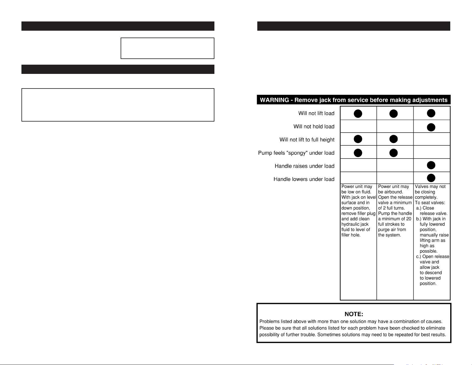
WARNING
It is the owner and/or operators’ responsibility to study all WARNINGS, operating, and maintenance
instructions contained on the product label and instruction manual prior to operation of this rapid lift floor
jack. The owner/operator shall retain product instructions for future reference.
The owner and/or operator are responsible for maintenance, maintaining all decals or warning labels and
while in use, maintaining the unit in good working order. If the owner and/or operator are not fluent in English,
the product warnings and instructions shall be read and discussed with the operators’ native language by the
purchaser/owner or his designee. Make sure that the operator comprehends its contents. Safety information
shall be emphasized and understood prior to usage. The rapid lift floor jack shall be inspected per the
operating instructions.
Users of this rapid lift floor jack must fully understand these instructions. Each person operating this rapid lift
floor jack must also be of sound mind and body and must not be under the influence of any substance that
might impair their vision, dexterity, or judgment.
Protect yourself and others by observing all safety information.
Failure to comply with instructions could result in personal injury and/or property damage!
If you encounter any problems or difficulties, please contact our customer service department at:
1-800-426-1262 between 6:30 a.m. and 4:30 p.m. Pacific time.
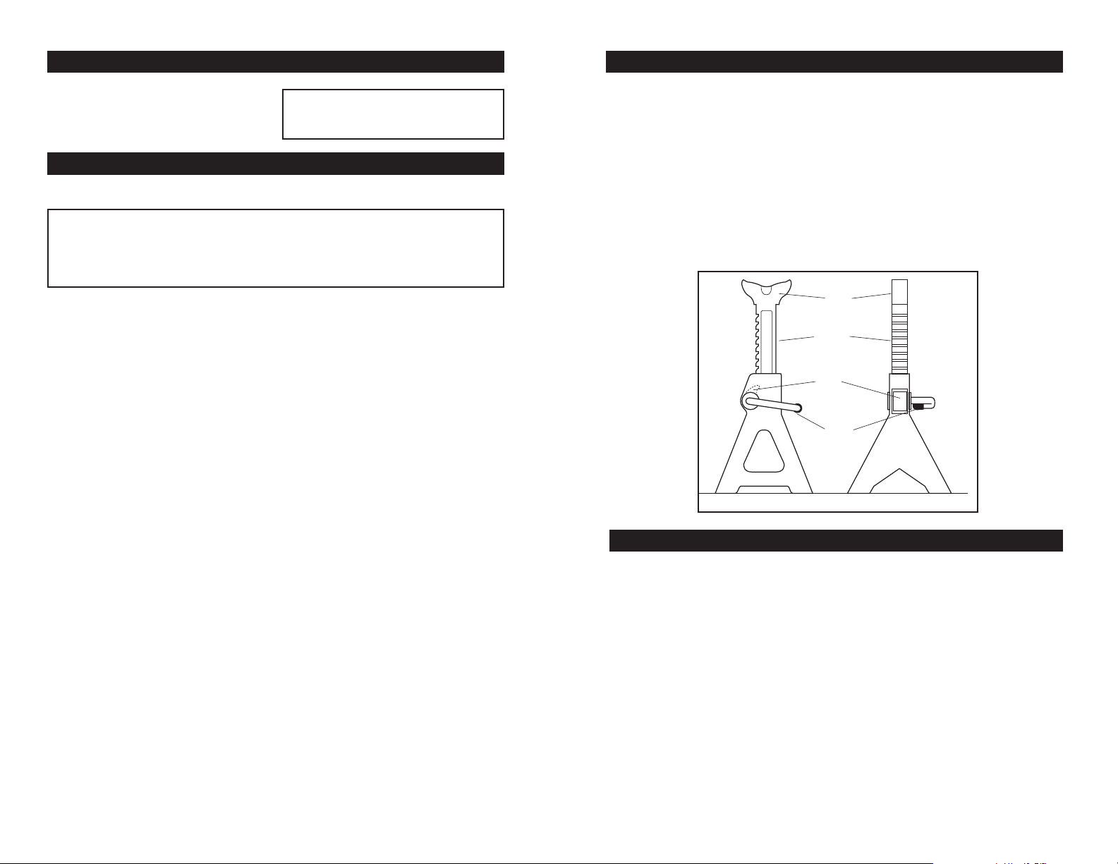
2 TON TROLLEY JACK
& JACK STANDS
OWNER’S MANUAL
Item Number W1605

RAM ASSEMBLY - JACK
Ram Assembly Parts List
OPERATION - JACK
Before using your jack:
1. Turn release valve counter-clockwise to open. Pump jack handle
about 6 full strokes to assure complete distribution of hydraulic
fluid. (See Figure 1)
To raise:
Turn release valve clockwise to close.
Make certain that load is on center of
saddle. Pump the jack handle to raise
load to desired height. Never exceed the rated load value.
Transfer load to jack stands provided, use in pairs ONLY. Always
use appropriate supports before working under load. (See figure 2)
To lower:
Raise load slightly to remove jack
stands. Slowly turn release valve
counter-clockwise just enough to allow
controlled descent. (Never turn
counter-clockwise more than 3
full turns)
1. When jack is not in use, lifting arm and handle sleeve should be in
fully down position to keep their precision machined surfaces free
from corrosion.
2. Keep jack clean and well lubricated. (See figure 3 )
3. For best results, use only hydraulic fluid with a rating of SAE 10 for
refills. Check fluid level with jack in fully down position. Fluid level
should be 5mm below filler hole. (See figure 5)
4. Regularly check for loose, worn or damaged parts and repair or
replace as necessary.
5. Replace worn or damaged parts
with Performance Tool
replacement parts. Be sure that
only qualified personnel perform
repairs.
CARE & MAINTENANCE - JACK
Figure 3
Figure 2
Figure 1
Figure 6
# Description Qty. # Description Qty.
1 Hydraulic Unit Body 1 21 Pump Piston 1
2 3/16 in. Steel Ball 2 22 Piston Clamp 1
3 Filter Body Screen 1 24 Handle Sleeve 1
4Copper Washer 1 26 Piston Pin 1
5 Pump Cylinder O-Ring 1 27 Connecting Pin 1
7 Ram Collar 1 28 Retaining Pin 2
8 Ram 1 30 5/16 in. Steel Ball 1
9 Cylinder 1 31 Release Valve Spacer 1
10 Fiber Washer (B) 1 32 Release Valve O-Ring 1
11 Oil Chamber 1 33 Release Valve 1
12 Oil Fill Plug 1 34 Spring Guide 1
13 Fiber Washer (A) 1 35 Overload Valve Spring 1
14 Top Nut 1 36 O-Ring 1
15 Top Nut O-Ring 1 37 Adjusting Screw 1
16 1/4 in. Steel Ball 1 38 Cap 1
17 Pump Cylinder 1
19 Pump Cylinder O-Ring 1
20 Back Up Ring 1

JACK ASSEMBLY
Figure 4
# Description Qty. # Description Qty. # Description Qty.
39 Return Spring *1 54 Front Wheel Spindle 1 69 Snap Ring 2
40 Lock Washer 4 55 Body Spindle 1 70 Pump Handle 1
41 Nut 6 58 Left Side Member 1 72 Cover Plate 1
44 Caster Wheel Assy. *2 60 Radius Link 2 73 Support Bar 1
47 Right Side Member 1 61 Retaining Ring 2
48 Flat Washer 2 62 Lifting Arm 1
49 Lock Washer 2 63 Cross Head Pin 1
50 Nut 2 64 C 19 Retaining Ring 1
51 Front Wheel Spacer 2 65 Lifting Arm Spindle 1
52 Front Wheel 2 67 Saddle Assembly 1
53 Flat Washer 2 68 Radius Link Pin 1
Replacement Parts
W1605CK Ram Repair Kit
W1605-39 Return Spring
W1605-44 Caster Assembly
W1605-70 Pump Handle
* Notes the replacement parts

Your Performance Tool hydraulic jack was constructed of quality
materials and workmanship and will give you many years of trouble free
use when cared for as described in the "Care & Maintenance" section
on page 3. However, as with any mechanical device, periodic
adjustments are necessary to maintain a peak level of performance.
Should your jack be displaying any of the following symptoms, the
simple procedures shown below will correct the problem.
TROUBLESHOOTING
Read these safety warnings before operation.
WARNING!
Failure to heed these warnings may result in loss of load,
damage to jack, and/or jack failure resulting in personal injury
or property damage.
WARNING!
This is a lifting device only. Do not move load while it is on the
jack. Load must be supported immediately by Jack Stands or
other appropriate means.
Do not overload jack beyond rated capacity. Overloading can
cause damage to or failure of the jack.
REFER TO YOUR VEHICLE OWNERS MANUAL FOR PROPER
JACKING PROCEDURES. Lift only on areas of the vehicle as
specified by the vehicle manufacturer.
This jack is designed for use only on hard level surfaces
capable of sustaining the load. Use of jack on other than hard
level surfaces can result in jack instability and possible loss of
load.
Be sure all personnel are clear of load before lowering load.
Ensure that no personnel pass underneath load until load is
securely supported by jack stands.
SPECIFICATIONS
Capacity: .................... 4,000 lbs.
Low Height: .................. 5-1/8 in.
Max. Height: ...................... 13 in.
Lift Range: .................... 7-7/8 in.
Specifications are subject to
change without notice
IMPORTANT SAFETY INFORMATION

OPERATION - JACK STANDS
Read these safety warnings before operation.
WARNING!
Failure to heed these warnings may result in loss of load,
damage to jack, and/or jack failure resulting in personal injury
or property damage.
WARNING!
Do not overload jack stands beyond rated capacity.
Overloading can cause damage to or failure of the jack stands.
POSITION LOAD ON CENTER OF SADDLE ONLY. ALWAYS USE
STANDS IN PAIRS ON HARD, LEVEL SURFACE CAPABLE OF
SUSTAINING THE LOAD. USE OF STANDS ON OTHER THAN
HARD LEVEL SURFACES CAN RESULT IN STAND INSTABILITY
AND POSSIBLE LOSS OF LOAD.
Be sure all personnel are clear of load before lowering load.
Ensure that no personnel pass underneath load until load is
securely supported by jack stands.
SPECIFICATIONS - JACK STANDS
Capacity: .................... 4,000 lbs.
Low Height: ................ 10-3/8 in.
Max. Height: ............... 16-3/8 in.
Lift Range: ........................... 6 in.
Specifications are subject to
change without notice
IMPORTANT SAFETY INFORMATION
MAINTENANCE & INSPECTION - JACK STANDS
1. Refer to your vehicle owner's manual for proper jacking procedures.
Lift only on areas of the vehicle as specified by vehicle manufacturer.
2. Position stands under vehicle at points specified by vehicle manufacturer
as proper load support points.
3. To adjust stands: Hold control lever up while lifting saddle shaft to desired
height. Push control lever down to lock pawl into teeth located in center
column. MAKE SURE PAWL IS FULLY ENGAGED INTO TEETH.
4. Carefully lower load onto stands.
Saddle
Pawl
Center
Column
Control
Lever
1. Visual inspection shall be made before each use of the stands, checking
for cracks, cracked welds and missing and/or damaged parts. Any stand
that appears to be damaged in any way shall be removed from service
immediately.
2. BECAUSE OF THE POTENTIAL HAZARDS ASSOCIATED WITH THE
MISUSE OF EQUIPMENT OF THIS TYPE, NO MODIFICATIONS SHALL
BE MADE TO THE PRODUCT.
Table of contents
Other PT Jack manuals