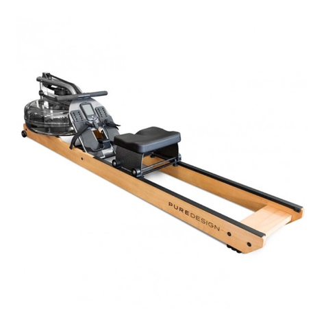
Pure Design Fitness AB10 User manual

PLEASE READ THIS INSTRUCTION
MANUAL
BEFORE YOU BEGIN EXERCISING
CONTACT INFO
Address: 72 South Street, Rydalmere,
NSW 2112
Phone: 02 9808 1405
ITEM NO.: AB10
OWNER’S MANUAL

Safety Information
Assembly Instruction
Features Instroduction
Console Instroduction
Exploded Diagrams
Parts List
03
04
12
13
16
17

3
Safety Information
PLEASE READ THIS INSTRUCTION MANUAL BEFORE YOU BEGIN EXERCISING. GREAT
CARE HAS BEEN TAKEN TO DESIGN THESE INSTRUCTIONS AND FOLLOWING THEM
WILL HELP YOU FOR QUICK ASSEMBLY AND MINIMIZE THE RISK OF INJURY
.
• Always assemble and operate the product on a level surface.
• Always ensure that the product is stable before use.
• Always ensure that the equipment has adequate space on each side and front and back.
• Ensure that the seat height is adjusted to fit the appropriate disance between pedals and legs.
• Stability and balance should be maintained while riding.
• Try to keep your body straight while exercising, especially for long period training.
• Regular examina�on of component wear should be done to ensure the safety of product.
• Replace defec�ve components immediately. Keep the product out of use un�l it is repaired.
• Follow only the adjustment instruc�ons described in the manual, with the appropriate hardware.
• Always perform checking of screws and bolts prior to the exercising. Make sure every parts are �ghtened.
• Always consult your doctor before proceed any exercise program.
• Always wear suitable clothing and footwear for the training.
• Remove all personal jewelry before exercising.

5
Assembly Instruction
Before you start
1.
Prepare your work area
It isimportant you assemble
the product in a clean and
uncluttered space.
2.
Work with a friend
We recommend you have
someone assist you with
the assemblyassomeof the
components are quite heavy.
3.
Open the carton
Check all the warnings on
the carton and make sure you
have it the right way up.
4.
Unpack the carton
Make sure you have
the following parts:
Hardware Tools and Consumables
Part
Part
Wrench
(14/17)
Allen Key (4,5,6mm)
Wrench
Phillips Screwdriver
Part #83
Foot Peg x 2 pcs
Part #38, #39
Pedal Set x 1 pair
Part #74
Fix Plate x 2 pcs
Part #46
Edn Cap x 2 pcs
Part #78
Bottle Holder x 1 pc
Part #40
Front Stabilizer x 1 pc
Part #44
Rear Stabilizer x 1 pc
Part #1
Main Frame x 1 pc
Part #51
Left Handlebar x 1 pc
Part #85
Console x 1 pc
Part #48
Console Support Frame x 1 pc
Part #52
Right Handlebar x 1 pc
Part #108
Allen Head Bolt
M10 x 20mm
x 8 pcs
Part #75
Conical Sleeve x 2 pcs
Part #93
Nylon Locknut
M8
x 2 pcs
Part #105
Screw
M8 x 30mm
Part #107
Screw
M6 x 15mm
Part #117
Arc Washer x 8 pcs
x 6 pcs
x 4 pcs

6
Step1:FrontStabilizerAssembly
(1)Removethecardboardtubefromthefrontstabilizerbracket
LoosentwoButtonHeadHexScrewM10*20(#108)from
thefrontstabilizerbracketandremovethecardboardtube.
Thecardboardtubeisusedforpackagingprotectionpurpose,andwillnotbe
usedagainduringtheassembly.
108
cardboard tube
(2)AttachtheFrontStabilizer
Attach the Front Stabilizer Tube (#40) to the Main Frame
(#01), with four ButtonHeadHexScrewM10*20(#108)and
ArcWasher(#117).UseAllenWrench6mm(#113)totighten
allscrewsandwashers.
Makesurethescrewsare
fullytightened.
Besuretofitthepartsinthe
sameorderasthediagrams
shown.

7
Step2:RearStabilizerAssembly
(1)Removethecardboardtubefromtherearstabilizerbracket
LoosentwoButtonHeadHexScrewM10*20(#108)fromtherearstabilizer
bracketandremovethecardboardtube.
Thecardboardtubeisusedforpackagingprotectionpurpose,andwillnotbe
usedagainduringtheassembly.
108
cardboard tube
(2)AttachtheRearStabilizer
AttachtheRearStabilizerTube(#44)totheMainFrame(#01),
withfourButtonHeadHexScrewM10*20(#108)and Arc
Washer(#117).UseAllenWrench6mm(#113)totightenall
screwsandwashers.
Makesurethescrewsare
fullytightened.
Besuretofitthepartsinthe
sameorderasthediagrams
shown.
No.
J4
Pa

8
Makesurethescrewsarefully
tightened.
Besuretofitthepartsinthe
sameorderasthediagrams
shown.
Step3:DualActionHandlebarAssembly
(1)AttachtheLeftDualActionHandlebar
Attachthe
LeftDualActionHandlebar(#51)
ontothepivotaxlecarefully.
InstalltheFeetPeg(#83)on.
Attach
the
FeetPegCap(#84)ontotheFeetPeg(#83).
(2)AssembletheLeftSwingArmLinkage
ConnecttheLeftDualActionHandlebar(
#51
)andConnection
Bracket(#74),withConicalSleeve(#75),HeadHexScrew
M8*30(#105),andNylonNutM8(#93).UseAllenWrench
5mm(#113)andMultifunctionWrench(#114)totightenall
screws.
DoublesecuretheConnectionBracket(#74)ontotheLeftSwingArmLinkage(#26),
withthreeFlatHeadHexScrewM6*15(#107)byAllenWrench4mm(#113).
51
105
74
75
107
93
Makesurethefootpegisfully
tightened.
Besuretofitthepartsinthe
sameorderasthediagrams
shown.
Part
No.
No.
No.
J2
Pt

9
(3)AttachtheRightDualActionHandlebar
Attachthe
RightDualActionHandlebar(#58)
ontothepivotaxlecarefully.
InstalltheFootPeg(#83)on.
Attach
the
FeetPegCap(#84)ontotheFeetPeg
(#83).
(4)AssembletheLeftSwingArmLinkage
ConnecttheRightDualActionHandlebar(
#58
)and
ConnectionBracket(#74),withConicalSleeve(#75),Head
HexScrewM8*30(#105),andNylonNutM8(#93).UseAllen
Wrench5mm(#113)andMultifunctionWrench(#114)to
tightenallthescrews.
DoublesecuretheConnectionBracket(#74)ontotheLeftSwingArmLinkage(#26),
w i t h t h r e e FlatHeadHexScrewM6*15(#107)byAllenWrench4mm(#113).
Makesurethescrewsarefully
tightened.
Besuretofitthepartsinthe
sameorderasthediagrams
shown.
Makesurethefootpegisfully
tightened.
Besuretofitthepartsinthe
sameorderasthediagrams
shown.
58
74
105
75
93
107
No.
J3
Part
No.
A17
Part
No.
G2
N.
J2
Part

10
Step4:PedalAssembly
(1)AttachtheLeftPedal
LoosentheSocketHeadScrewM6*10
(#109)installedontheLeftCrankArm.
AttachtheLeftPedal(#38)totheLeftCrank
Arm.
FastenthepedalwithSocketHeadScrew
M6*10(#109)byAllenWrench5mm(#113).
(2)AttachtheRightPedal
LoosentheSocketHeadScrewM6*10
(#109)installedontheRightCrankArm.
AttachtheRightPedal(#39)totheRight
CrankArm.
FastenthepedalwithSocketHead
ScrewM6*10(#109)byAllenWrench
5mm(#113).
Besuretofitthepartsinthe
sameorderasthediagrams
shown.
Thispedalwillbethreadedon
clockwisely.
Makesurethescrewisfully
tightened.
Thispedalwillbethreadedon
clockwisely.
Besuretofitthepartsinthe
sameorderasthediagrams
shown.
Makesurethescrewisfully
tightened.
39
109
38
109

11
Makesurethescrewsarefully
tightenedwiththeallenkey.
Step5:ConsoleSupportAssembly
ConnecttheBottomSensorWireandMiddleSensor
Wiretogether,andthenattachtheConsoleSupport
Tube(#48)tothefrontendoftheMainFrame(#01),
withtwoFlatHeadHexScrewM8*30(#105).
Step6:ConsoleAssembly
RemovethefourButtonHeadPhillipsScrewM5*12(#106)
whicharelocatedonthebackoftheConsole(#85).
ConnecttheConsoleCableandMiddleSensorWire
together.ThenattachtheConsole(#85)totheConsole
SupportTube(#48),withfourButtonHeadPhillipsScrew
M5*12(#106).
Besuretofitthepartsinthe
sameorderasthediagrams
shown.
Makesurethecablesand
wiresarefullyconnected.
Makesurethescrewsarefully
tightened.
Makesurethecablesarefully
connected.
Besuretofitthepartsinthe
sameorderasthediagrams
shown.
FIXINGS:
Part
D4
No.
Bottom
SensorWire
MiddleSensorWire

12
Step 7: Water Bottle Holder Assembly
AttachtheWaterBottleHolder
(#78)totheConsoleSupport
Tube(#48)andfastenitwithtwo
ButtonHeadPhillipsScrew
M5*12(#106).Thenplacethe
WaterBottle(#118)in.

12
Features Introduc�on
(1) Horizontal Adjustment
1.
Horizontal Adjustment
Bracket (#62) to adjust toeat
Cus
2.
e Horizontal Adjustment
Bracket (#62) stment is
.
(2)
1.
Pressure Handle (#76) and
adjust te eigt eat Cun.
2.
Press down te Pressure Handle (#76)
e adjustment ileted.
1. To lace,
Adjustment Feet (#45) cae turned to te surace.
(4) or
1.
Liti e rear ster teand
mae sure te 2 Transport Wheel (#43) touc
in order to move te ound.
62

13
STARTENTERSTOP
Interval
Target
time
Target
distance
Target
calories
WARNING:
Heart rate monitoring systems
may be inaccurate.If you feel
pain, faintness,or dizziness,
stop exercising immediately.
Target
HR
Console Introduc�on

Operating the console:
1. QUICK START OPERATION
Under STAND BY display, the user can enter “QUICK START” mode by pressing the “START” button. And then
“TIME, DISTANCE, CALORIES” will ready to count up from zero. After starting the machine, the lever of resistance
can be adjusted manually. The system will pause counting TIME/DISTANCE/CALORIES if not receiving RPM
signals. The system will continue previous counting once receiving RPM signal. While using, pressing “STOP”
button will cease the operation of the console.
2. INTERVAL – PROGRAM
Under STANDBY DISPLAY, pressing “INTERVAL” button one time can enter default setting of interval 20/10
program ; pressing two times continuously can do the setting in Interval 10/20 program ; pressing three times
continuously can enter Interval Custom Program to set your own settings.
(A). Setting interval laps on Interval 20/10 Program
Under operating status, when choosing Interval 20/10, Internal 0/10 display will blink, the user can do the setting
using “UP/DOWN” button. Press “ENTER” when setting is finished and then press “START” to run the program.
When pressing “START”, the program will operate based on WORK TIME 20 seconds/ REST TIME 10 seconds.
Interval takes record on each cycle until reaching the setting laps.
(B). Setting Interval laps on INTERVAL 10/20 program
Under STANDBY mode, when choosing INTERVAL 10/20 program, “ INTERVAL 0/10” display will blink. Use
“UP/DOWN” button to do the setting. Press “ENTER” when finishing the setting and then press “START” to start the
workout.
When pressing “START”, the program will operate based on WORK TIME 10 seconds/ REST TIME 20 seconds.
Interval takes record on each cycle until reaching the setting laps.
(C). Operation on INTERVAL CUSTOM mode
Under STANDBY DISPLAY, when choosing “INTERVAL CUSTOM”, “WORK TIME” will blink.
(1). Setting “WORK TIME”
Use “UP/DOWN” button to set the time on “WORK TIME”. Press “ENTER” when finish the setting, and the program
will switch to display on the next setting column.
(2). Setting “REST TIME”
Use “UP/DOWN” button to set the REST TIME. Press “ENTER” when finish the setting, and the program will switch
to display on the next setting column.
(3). Setting on INTERVAL laps
Use “UP/DOWN” button to set the INTEVAL laps. Press “ENTER” when the setting is finished. Press “START” to
begin the workout.
When pressing “START”, the program will operate based on WORK TIME/ TEST TIME the user has set. Interval
takes record on each cycle until reaching the setting laps.
14

3. TARGET TIME – PROGRAM
Under STANDBY DISPLAY, pressing “TIME” program will enter the operation of this program.
(1). Setting TIME
When choosing TIME PROGRAM and pressing “ENTER”, the program switch to the default time of 30 seconds in
blinking display.
Press “UP/DOWN” button to set TIME or not changing the default time, press “ENTER” to save the setting.
(2). The processing mode after “START”
a. Under processing mode, TIME counts in decrement, DISTANCE/CALORIES counts in increment.
b. Console will stop function when pressing “STOP” during operation.
4. TARGET DISTANCE – PROGRAM
Under STANDBY DISPLAY, press “DISTANCE” program to enter the setting of this program.
(1). Setting DISTANCE
When choosing DISTANCE PROGRAM and pressing “ENTER”, the program switches to the default setting of 5.00
and display in blink.
Press “UP/DOWN” button to set DISTANCE or not changing the default distance. Press “ENTER” to save the setting.
(2). The processing mode after “START”
a. Under processing mode, DISTANCE display counts in decrement, TIME/CALORIES counts in increment.
b. Console will stop function when pressing “STOP” during operation.
5. TARGET CALORIES – PROGRAM
Under STANDBY DISPLAY, pressing “CALORIES” program to enter the setting of this program.
(1). Setting CALORIES
When choosing CALORIES PROGRAM and pressing “ENTER”, the program switches to the default setting of 50
calories and display in blink.
Press “UP/DOWN” button to set CALORIES or not changing the default calories. Press “ENTER” to save the setting.
(2). The processing mode after “START”
a. Under processing mode, CALORIES display counts in decrement, TIME/DISTANCE counts in increment.
b. Console will stop function when pressing “STOP” during operation.
6. TARGET HR PROGRAM
Under STANDBY DISPLAY, press “HR” program to enter the setting of this program.
(1). Setting AGE
When pressing HR program, console displays initial age setting of 30 years old. Press “UP/DOWN” button to setting
age, and press “ENTER” to save the setting. Press “START” to begin the workout.
(2). The processing mode after “START”
a. Under processing mode, TIME/DISTANCE/CALORIES display counts in increment.
b. Console will stop function when pressing “STOP” during operation.
15

Exploded Diagram

PartsList
NO. DESCRIPTION OF PARTS Q'TY NO. DESCRIPTION OF PARTS Q'TY
01 Main Frame 1 45 Adjustment Feet 1
02 Fan Wheel Hub Set 1 46 Round Feet Pad 2
03 Fan Wheel 1 47 Rear Stabilizer Cap 1
04 Fan Wheel Spacer Φ16 1 48 Console Support Tube 1
05 Fan Wheel Spacer Φ19 1 49 Support Tube Cap 2
06 Fan Axle 1 50 Wire Plug 2
07 Bearing 6301Z 1 51 Left Dual Action Handlebar 1
08 Bearing 6901Z 3 52 Dipping Handle 1
09 Left Fan Cage 1 53 Bearing 6003Z 2
10 Right Fan Cage 1 54 Bearing 6202Z 2
11 Fan Cage Ring 1 55 Bearing 6203Z 2
12 Fan Cage Fixation Plate 2 56 C Ring (for Bearing 6203Z) 2
13 Stopper 2 57 Handlebar Tube Cap 2
14 Bolt M8*45 2 58 Right Dual Action Handlebar 1
15 Nut M8 2 59 Dipping Handle 1
16 Crank Axle 1 60 Seat Tube (for Vertical Adjustment) 1
17 Pulley 1 61 Seat Tube (for Horizontal Adjustment) 1
18 Right Crank 1 62 Horizontal Adjustment Bracket 1
19 C Ring Φ6 (for Crank Axle) 1 63 Horizontal Adjustment Bracket Cover 1
20 Spring Pin 1 64 Short Shaft for Horizontal Adjustment Bracket 1
21 Bearing 6005 2 65 Long Compression Spring 1
22 Crank Lock Nut 1 66 Stopper Ball 1
23 Left Crank 1 67 Short Compression Spring 1
24 Left Crank Disc 1 68 Adjustment Spacer 1
25 Bearing 22052RS/NR 2 69 Long Shaft for Horizontal Adjustment Bracket 1
26 Left Swing Arm Linkage 1 70 Ball Pin 1
27 C Ring (for Bearing 22052RS/NR) 4 71 Square Plug 1
28 Right Crank Disc 1 72 Seat Carriage 1
29 Ring Swing Arm Linkage 1 73 Seat Cushion 1
30 Left Housing 1 74 Connection Bracket of Left Swing Arm 1
31 Right Housing 1 75 Conical Sleeve 2
32 Large Plastic Cover (for Crank Disc) 1 76 Pressure Handle 1
33 Small Plastic Cover (for Crank Disc) 1 77 Collar 2
34 Left Side Cover 1 78 Water Bottle Holder 1
35 Right Side Cover 1 79 Thin Adjustment Plate 1
36 Plastic Cover (for Seat Tube) 1 80 Thick Adjustment Plate 1
37 Belt 1 81 Compression Block 1
38 Left Pedal 1 82 Reset Spring 1
39 Right Pedal 1 83 Aluminum Alloy Feet Peg 2
40 Front Stabilizer Tube 1 84 Feet Peg Cap 2
41 Front Stabilizer Cap 2 85 Console (include Bottom Sensor Wire and Middle Sensor
Wire) 1
42 Square Feet Pad 2 86 Magnet 1
43 Transport Wheel 2 87 Socket Head Screw M8*20 1
44 Rear Stabilizer Tube 1 88 Socket Head Screw M5*12 8

NO. DESCRIPTION OF PARTS Q’TY NO. DESCRIPTION OF PARTS Q’TY
89 Hex Nut M12 4 106 Button Head Phillips Screw M5*12 4
90 Socket Head Screw M6*12 6 107 Flat Head Hex Screw M6*15 6
91 Socket Head Screw M10*40 4 108 Button Head Hex Screw M10*20 8
92 Socket Head Screw M6*20 1 109 Socket Head Screw M6*10 2
93 Nylon Nut M8 5 110 Button Head Hex Screw M8*50 1
94 Flat Washer M8 3 111 Spring Washer M8 1
95 Socket Head Screw M6*16 1 112 Socket Head Screw M5*6 3
96 Button Head Phillips Self-tapping Screw ST4*10 7 113 Allen Wrench 4MM/ 5MM/ 6MM 1/ 1/ 1
97 Flat Head Phillips Screw M6*15 2 114 Multifunction Wrench 1
98 Nylon Nut M6 1 115 Wrench 1
99 Socket Head Screw M6*35 1 116 Phillips Screwdriver 1
100 Phillips Self-tapping Screw ST4*15 12 117 Arc Washer 8
101 Flat Head Phillips Screw M4*10 4 118 Water Bottle 1
102 Button Head Hex Screw M8*50 2 119 Small Compression Spring 2
103 Cap Nut M8 3 120 Right Plastic Cover (for Seat Tube) 1
104 Button Head Phillips Screw M5*8 4 121 Left Plastic Cover (for Seat Tube) 1
105 Flat Head Hex Screw M8*30 4
Table of contents
Other Pure Design Fitness Fitness Equipment manuals
Popular Fitness Equipment manuals by other brands

Stages cycling
Stages cycling SP3 manual

Hoist Fitness
Hoist Fitness ROC-IT RS-1203-A owner's manual

STAR TRAC FITNESS
STAR TRAC FITNESS PVS installation manual

Vita Vibe
Vita Vibe ASB36-90 Assembly guide

Merrithew Health & Fitness
Merrithew Health & Fitness Cadillac owner's manual

Ironman Fitness
Ironman Fitness 5201 owner's manual