Page 6
Operation
1. Check to ensure that access door is securely in place.
WARNING
Risk of carbon monoxide poisoning.
Can cause injury or death.
Do not operate system unless access door is in
place and properly secured. Operation of this equip
ment without the PCO access door in place may
cause exhaust fumes to be drawn into occupied
spaces.
2. Lamps should remain illuminated continuously except
during service and maintenance.
3. For optimal odor control, air handler blower should
remain on continuously (thermostat fan setting in ON
position, rather than AUTO).
If air handler does not provide a continuous low blower
speed option, an additional blower relay should be
installed. Use Lennox part number 45H03. Phone Lennox
Application Department at 1-800-453-6669 for wiring
information. Lennox units which include the SureLight®
integrated control do not require the use of an additional
relay.
NOTE - Continuous fan operation may result in higher
humidity. If humidity levels are uncomfortably high, fan
setting should be switched to AUTO during cooling
operation.
Filter, Insert and Lamp Replacement
The PCO MERV 16 filter, PureAir Insert and UVA lamps
require annual replacement. More frequent replacement
may be required in applications with heavier dust or dirt
loads or if you notice a reduction in odor-removal
efficiency. An annual maintenance kit, which includes a
replacement MERV 16 filter, a replacement PureAir
Insert and two replacement UVA lamps, is available
through Lennox . See “Annual Maintenance Kit” (Page 7)
for applicable kit part number.
WARNING
Electric shock hazard.
Can cause injury or death.
Disconnect all electrical power supplies before ser
vicing.
CAUTION
Personal Burn Hazard.
Lamps become very hot when illuminated.
Allow lamps to cool for 10 minutes before removing
lamp from socket.
Injury may result from contact with hot lamps.
1. Unpack the replacement MERV 16 filter, UVA lamps
and PureAir Insert which are provided in the
Replacement Kit. Remove all protective wrapping
materials.
2. Unplug the power cord and remove the PCO access
door.
3. Slide out the control box assembly and remove the
existing MERV 16 filter.
4. Check air flow direction of the MERV 16 filter and
insert replacement filter into the PCO cabinet.
5. Remove the existing PureAir Insert from the
cabinet.
NOTICE
Do not wash PureAir™ Insert. Soap and water will
destroy the titanium dioxide catalyst that coats the
insert surface.
6. Check air flow direction of the replacement PureAir
Insert and slide the PureAir Insert into the cabinet.
7. Wipe down reflectors using cotton cloth to remove
finger prints and contaminants.
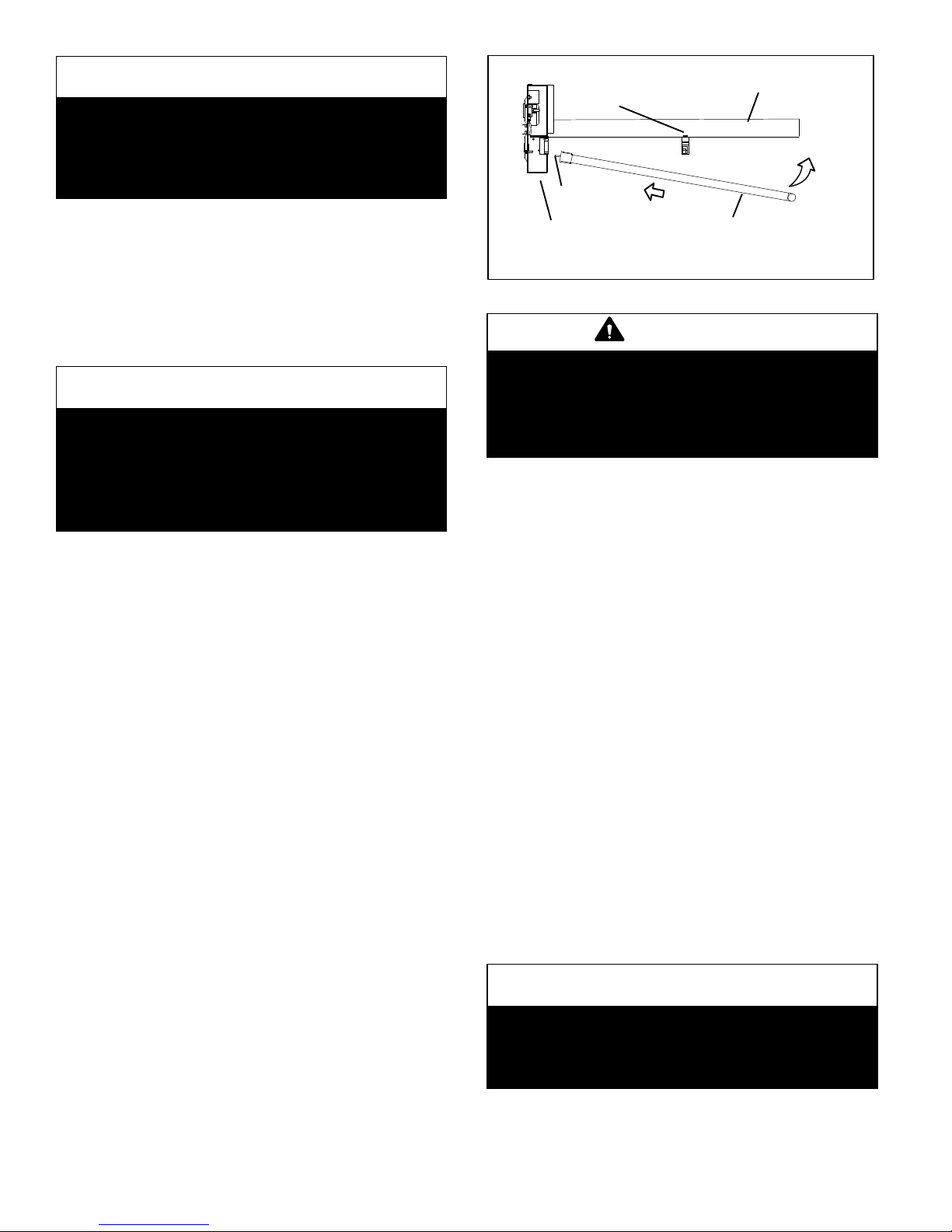
8. Pivot the lamp away from the reflector until lamp is
released from the securing clip. Gently pull lamp out
of the lamp socket taking care not to break the lamp.
9. Remove one replacement lamp from the box. Position
the lamp with the pin end closest to the lamp socket.
While engaging the pins in the socket, pivot the lamp
so that the securing clip on the reflector locks into the
open space in the middle of the lamp. See figure 5.
10. Gently pull on lamp to ensure that lamp securing
clip is engaged.
11. Repeat steps 8 and 9 to replace second lamp.
12. Slide control box assembly back into PCO cabinet.
13. Securely fasten access door and reconnect power
cord.
14. Look through the view port in the access door to check
that the lamps are illuminated.
NOTE - On initial start-up, the lamps may not reach full
illumination for several minutes.
CAUTION
Ultraviolet (UVA) radiation risk.
Prolonged exposure may cause skin or eye damage.
Avoid prolonged (weeks) exposure to skin or eyes.
NOTICE
If the system has been operated for a period of time
without the lamps being illuminated, an odor may
occur when lamps are illuminated. This odor is con
sidered typical and should dissipate within 12 hours
of full operation. If the odor does not subside after
48 hours of operation, instruct the homeowner to
unplug the PCO unit and contact a Lennox dealer.