Purkeys SELECT User manual

A MISSION CRITICAL ELECTRONICS BRAN
D
SELECT™& DIRECT™NOSEBOX
INSTALLATION GUIDE
300-18 R4.00


1
P: 479.419.4800 | F: 479.419.4801 | www.purkeys.net
CONTENTS
General Information ..........................................................................................2
Dual/Single Nosebox Installation.....................................................................3
Aux Harness Installation ...................................................................................4
7-Way Nosebox Tips ..........................................................................................6
Main Harness Installation.................................................................................7
Interior Light Installation without Severe Service .......................................11
Installation Connections Outside the Nosebox..................................11
Interior Light Installation with Severe Service.............................................12
Momentary Switch (optional).........................................................................13
LED Logic..........................................................................................................14
Interior Light Control ............................................................................18
Limited Commercial Warranty Policy...........................................................21

2
e Purkeys Select™ and Direct™ nosebox systems improve ligate battery
charging by utilizing a DC/DC converter to boost the voltage for optimal
charging.
e boost in voltage overcomes the normal voltage drop caused by the
extended distance between the ligate batteries and the vehicle charging
system. Also, in cold temperatures batteries require increased charging
voltages to maintain a high state of charge. e DC/DC converter
compensates for temperature by providing higher charging voltages in cold
weather. e result is well-charged ligate batteries that will last longer and
have ample power for ligate operation.
NOTE: Our ligate charging systems are designed to work with ooded cell
and AGM batteries. If you are using this system to charge any other type of
battery, please contact us at 479-419-4800 before installation.
GENERAL INFORMATION

3
P: 479.419.4800 | F: 479.419.4801 | www.purkeys.net
SELECT/DIRECT INSTALLATION GUIDE
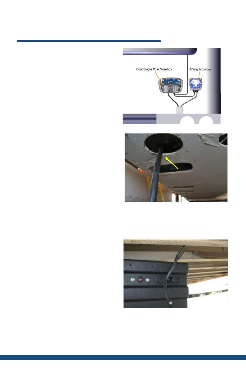
Step 1: Using the supplied mounting
screws, mount the dual/single
Select or Direct nosebox at the
front of the trailer, near the 7-way
nosebox, via the mounting holes
on the plate.
Charging
Good Voltage
Low Voltage
Fault
Over-Temp Prot.
Green Solid
Green Blink
Orange Blink
Orange Rapid
Orange Solid
This product is patented. Includes 3-year warranty.
NOTE: The warranty will be void if the unit has
been drilled or modified. If you experience any
problems with this unit, please call 800-219-1269
and we will gladly assist you.
LED STATUS
L-098 R1.00
Note: Do not block the LED status
decal on the side of the Select/
Direct when mounting the
Nosebox.
Nosebox Mounting Complete.
DUAL/SINGLE NOSEBOX INSTALLATION
Note: e mounting plate can
be removed if space is an issue
or if a standard bolt pattern
is wanted. Simply remove the
plate and mount the nosebox
to the trailer using the supplied
mounting screws and the
standard bolt holes inside the
nosebox.

4
AUX HARNESS INSTALLATION
Step 1: Route the jacketed aux and
ground 2-conductor from the
nosebox controller over to the
7-way nosebox.
Note: Place the cable clamps along the 7-way aux harness every 6 inches
to ensure proper support for the cable. Avoid sharp edges and possible
chang points.
Step 2: Position the 2-conductor
harness so that is reaches the
ground pin on the top of the 7-way
receptacle and the aux pin in the
center of the 7-way receptacle.
Mark the cable, then cut to length.
Step 3: Slide the supplied red 1/4
inch heat shrink over the blue
wire.
Slide the supplied black 1/4 inch
heat shrink over the white wire.

5
P: 479.419.4800 | F: 479.419.4801 | www.purkeys.net
SELECT/DIRECT INSTALLATION GUIDE
Step 4: Crimp the supplied 10 gauge
#10 eyelets onto both the blue and
white wires.
Step 5: Solder, then position the heat
shrink over the crimps and apply
heat to the 2 terminals.
Note: Place the cable clamps along the 7-way aux harness every 6 inches
to ensure proper support for the cable. Avoid sharp edges and possible
chang points.
Aux Harness Installation Complete.

6
7-WAY NOSEBOX TIPS
SERVICE TIP - Purkeys oers the Ligate Double Check tool, which
can simplify the diagnosis of ligate charging system problems
caused by excessive voltage drop. For more information on the tool,
please call 1-800-219-1269 or visit our website at www.purkeys.net.
• Inspect circuits inside the 7-way box for excessive electrical resistance
caused by overheating, corrosion, loose/poor connections, or
undersized wiring.
• Check to see if the 7-way nosebox is equipped with circuit breakers
(see Figure 1), as the problem may be a failing circuit breaker. Either
replace circuit breaker with a new part or connect the blue wire from
the nosebox controller to the unprotected side of the circuit breaker.
Circuit protection is provided by the 30 amp fuse inside the nosebox
controller.
• Ensure the 7-way or stinger cord has a tight t and has good electrical
contact at the tractor and trailer receptacles.
Figure 1: 7-Way Nosebox

7
P: 479.419.4800 | F: 479.419.4801 | www.purkeys.net
SELECT/DIRECT INSTALLATION GUIDE
Step 1: Route the 4-conductor
jacketed DC/DC converter main
harness behind the front plate,
then behind the header plate
through the air/electrical tube to
the center channel.
Step 2: Route the jacketed
4-conductor main harness in the
center channel toward the back of
the trailer. Secure with wire ties or
cable clamps as you go.
MAIN HARNESS INSTALLATION
Place the cable clamps along the 4-conductor jacketed wire every 6 inches
to ensure proper support for the cable. Avoid sharp edges and possible
chang points.
Step 3: Once you are near the ligate
battery box, begin routing the
4-conductor main harness into
the ligate battery box through a
dome nut or rubber grommet.
Note: Ensure that the 4-conductor jacketed wire enters the ligate battery
box through a dome nut or rubber grommet to prevent chang the wire,
which could result in possible electrical short in the system.

8
Step 6: Cut about 8 inches o the
jacketed portion o the conductor.
Step 7: Apply the supplied ¾ inch
black heat shrink where the jacket
was stripped o.
Step 4: Position the 4-conductor
main harness so it will reach the
2-stud strip and all the slack has
been taken up. Mark the wire so
it can be taken back out of the
battery box to be terminated.
Step 5: Pull the conductor out of the
box (easier to work on), and cut
o the excess at the mark.
Note: If your battery box includes a slide-out tray, include enough slack to
allow the tray to fully extend without tugging the wire connections.

9
P: 479.419.4800 | F: 479.419.4801 | www.purkeys.net
SELECT/DIRECT INSTALLATION GUIDE
Step 8: Strip 3/8 inch of insulation
o all 4 wires.
Step 9: Slide the supplied red 1/4
inch heat shrink over the orange,
yellow, and black wires. Slide
the supplied black 1/4 inch heat
shrink over the white wire.
Step 10: Crimp terminals onto the 4
wires. e white and black 8-gauge
wires use the 3/8 ring terminals,
and the orange 14-gauge wire and
yellow 16-gauge wire use the #10
ring terminals.
Step 11: Position the heat shrink
over the crimps and apply heat to
the 4 terminals.

10
Step 12: Re-route the jacketed wire
back into the battery box.
• Connect the 8-gauge black wire to the red positive Input Stud.
• Connect the 8-gauge white wire to the black ground stud.
• Connect the 14-gauge orange wire to the Ligate (+) stud.
• Connect the 16-gauge yellow wire to the Ignition stud.
Main Harness Installation Complete.

11
P: 479.419.4800 | F: 479.419.4801 | www.purkeys.net
SELECT/DIRECT INSTALLATION GUIDE
INTERIOR LIGHT INSTALLATION
WITHOUT SEVERE SERVICE
Figure 1
Reefer positive
Ground
Dual pole positive
Source
Interior light input power
Interior light output power
Light control
Fused power
Step 3: Terminate the negative input with a #10 ring terminal and connect to
the Ground pin inside the nosebox (see Figure 1).
Step 2: Terminate the positive input with a #10 ring terminal and connect to
the Interior light input power stud inside the nosebox (see Figure 1).
ese interior light instructions apply if you are installing the Purkeys interior
light harness (Purkeys Part Number H-00522: 50 Interior Light Harness) to
power interior lights o of the ligate or auxiliary battery.
Step 1: Route the Interior light input harness from the ligate/aux battery to
the nosebox and cut to length.
Installation Connections Inside the Nosebox:
Note: e Purkeys interior light harness (Purkeys Part Number H-00522:
50 Interior Light Harness) is sold separately as it is an optional device.
Note: Do NOT connect to the batteries until the interior light installation is
complete. Doing so may result in coming in contact with a live wire.

12
Step 1: Inside the nosebox, connect the severe service positive terminal to the
interior light input power terminal (see Figure 2) using a 10 gauge wire.
INTERIOR LIGHT INSTALLATION
WITH SEVERE SERVICE
Step 2: Terminate the Interior light positive wire with a #10 ring terminal and
connect to the Interior light input power (see Figure 2).
Step 3: Terminate the Interior light negative wire with a #10 ring terminal and
connect to Ground (see Figure 2).
Interior Light with Severe Service Installation Complete.
Severe service positive
Interior light input power
Ground
Figure 2
ese interior light instructions apply if you are installing the Purkeys severe
service kit (Direct Max only).

13
P: 479.419.4800 | F: 479.419.4801 | www.purkeys.net
SELECT/DIRECT INSTALLATION GUIDE
If your trailer is being spec’d with a momentary switch at the back of the
trailer (the momentary switch is not included in the Purkeys kit), wire the
circuit as shown below using the supplied pigtail harness shown in the
drawing below (Purkeys Part Number 800-196).
If you are using the pigtail harness for interior lights, but not for telematics,
trim o and heat shrink the purple telematics wire.
MOMENTARY SWITCH (OPTIONAL)
Momentary Switch
Trailer Ground
Interior Light/Telematics
Pigtail (Part# 800-196)

14
LED LOGIC
LED STATUS LOGIC
Solid Green
on Li
Battery and
Source
Charging State – Source voltage
is greater than 13.8 volts. DC/
DC converter is on. Tractor must
be running and alternator good
to achieve 13.8 volts. A battery’s
surface charge cannot reach this
value. Applies to all charging
sources.
Note: e turn-on voltage is 13.2
volts aer 5 minutes or 13.8 volts
immediately. is is because, in
Dual Pole in Parallel state, the
DIRECT input is now connected
to ligate batteries via the dual
pole cables. If the ligate batteries
had been charging using the
DC/DC converter, that voltage
would be above 13.2 volts, so
the DIRECT would turn on and
continue to charge even if the
tractor was shut o.
Source

15
P: 479.419.4800 | F: 479.419.4801 | www.purkeys.net
SELECT/DIRECT INSTALLATION GUIDE
LED STATUS LOGIC
Solid Green
on Source
Slow
Flashing
Orange on
Li Battery
Charging State – Tractor
connected and running. DC/DC
converter is operating, but the
ligate batteries are defective or
below 12.8 volts.
Applies to all charging sources.
Solid Green
on Li
Battery and
Source
Extend State – Source voltage
drops below 13.8 volts. DC/DC
converter is on for 1 hour. Every
two minutes the controller turns
o the DC/DC converter, so there
is no current ow (no voltage
drop) and measures the battery
voltage on the tractor batteries.
If over 12.4 volts, the controller
turns on for another two minutes.
is will repeat until 60 minutes
has expired, or the voltage drops
below 12.4 volts for 30 seconds.
e DIRECT will then look for
next available source.
No Source
LED
Li Battery
LED Slow
Flashing
Green
Static State – No tractor
connected to the trailer and the
ligate batteries are more than
12.4 volts.
w

16
LED STATUS LOGIC
No Source LED
Li Battery LED
Slow Flashing
Orange
Static State – No tractor
connected to the trailer and
the ligate batteries are less
than 12.4 volts.
Slow Flashing
Green on Li
Battery and
Source
O State – Source voltage
below 13.8 volts and extend
period is over. Voltage at
the li batteries and the
source is above 12.4 volts.
Voltage at source must
achieve 13.8 volts to go into
Charging State.
Applies to all charging
sources.
Slow Flashing
Orange on Li
Battery and
Source
O State (Low Voltage)
– Li battery and source
voltage below 12.4 volts.
DC/DC converter is o.
Voltage at source must
achieve 13.8 volts to go into
Charging State.
Applies to all charging
sources.
Rapid Flashing
Orange on Li
Battery and/or
Source
O State (Fault) – Voltage
between 2 and 9 volts.
Check fuses and wiring.
No LED
O State (Fault) – Open
circuit in li battery or
source circuit. is could
also be caused by the
ligate battery voltage
being below 6 volts.

17
P: 479.419.4800 | F: 479.419.4801 | www.purkeys.net
SELECT/DIRECT INSTALLATION GUIDE
LED STATUS LOGIC
Excessive Voltage Drop
– Tractor is running and
the voltage is above 13.8
volts. e controller turns
on the DC/DC converter
and current starts to ow.
If the voltage drops below
9 volts, the controller will
tell the DC/DC converter
to turn o. What the
operator will see is the
Source and Li Battery go
Solid Green. Both LEDs
will toggle orange for a
few seconds. e cycle
then repeats.
NOTE: Low voltage shut
o in the rst 5 minutes is
9.5 volts.
Solid White on
Interior Lights
e interior lights in the
trailer will turn o either
via a timer (which can
be set to 15, 30, 60, or 90
minutes) or if the ligate
batteries drop to a low
state of charge.

18
Interior Light Control
e interior light timer defaults to 60 minutes. However, it can be changed to
15, 30, 60, or 90 minutes. To change the timer length:
Press the “ON/OFF” button 10 times within 10 seconds
All LEDs will ash white once, then display current timer setting (see table
below)
Press the “ON/OFF” button to toggle to the desired timeout period (see table
below)
Timer set mode will exit 10 seconds aer the last button press (setting will be
saved as the most recent setting entered by user )
LED STATUS LOGIC
No LED
15 minute timer is
enabled/active
Solid White on Aux
30 minute timer is
enabled/active
Solid White on Aux
and Li Battery
60 minute timer is
enabled/active
Solid White on Aux,
Li Battery, and
Interior Lights
90 minute timer is
enabled/active
Other manuals for SELECT
1
This manual suits for next models
1
Table of contents
Other Purkeys Batteries Charger manuals

Purkeys
Purkeys SOLAR BOLT User manual

Purkeys
Purkeys DIRECT PLUS Setup guide

Purkeys
Purkeys BOSS-01 User manual

Purkeys
Purkeys DIRECT Setup guide

Purkeys
Purkeys SOLAR BOLT User manual

Purkeys
Purkeys DIRECT FLEX Setup guide

Purkeys
Purkeys DIRECT-03 User manual

Purkeys
Purkeys Select P1020-K User manual

Purkeys
Purkeys SELECT Setup guide

Purkeys
Purkeys Liftgate Double Check User manual