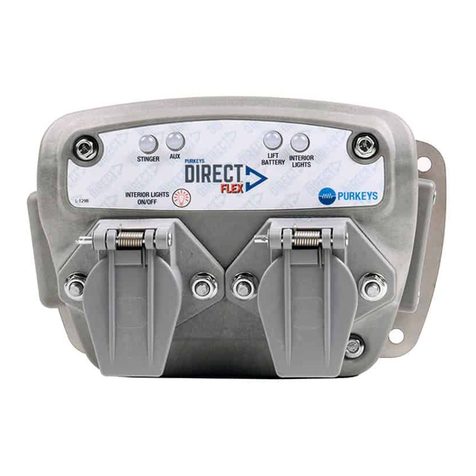
Purkeys DIRECT PLUS User manual

A MISSION CRITICAL ELECTRONICS BRAN
D
PLUS/FLEX/MAX NOSEBOX
INSTALLATION GUIDE
INST165 R7.00


1
P: 479.419.4800 | F: 479.419.4801 | www.purkeys.net
CONTENTS
General Information ..........................................................................................2
Diagrams .............................................................................................................3
Direct Plus .................................................................................................3
Direct Flex..................................................................................................4
Direct Max .................................................................................................5
Mounting the Nosebox......................................................................................6
Main Harness Installation.................................................................................7
Interior Light Installation without Severe Service .......................................11
Installation Connections Inside the Nosebox.....................................11
Interior Light Installation with Severe Service.............................................12
Interior Light Power from the 7-way Auxiliary Circuit ..............................13
Direct Plus Diagram: 7-way Interior Light Connection....................13
Direct Flex and Max Diagram: 7-way Interior Light Connection....14
Momentary Switch (optional).........................................................................15
Severe Service Installation (Max Only).........................................................16
Installing Cables to the Nosebox ..........................................................16
Routing the Severe Service Cables........................................................17
LED Logic..........................................................................................................20
Interior Light Control ............................................................................24
Interior Light Control Timer.................................................................25
Limited Commercial Warranty Policy...........................................................29

2
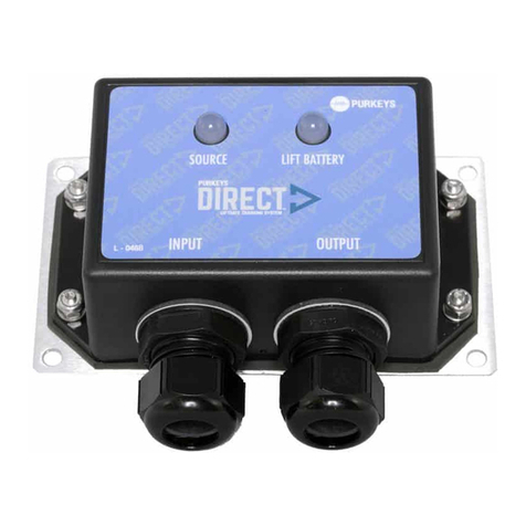
e Purkeys Direct™ nosebox system combines all the best features of
our original ligate charging systems with a space-saving nosebox that
helps standardize the front of the trailer. It also includes an interior light
controller (harness sold separately) designed to turn the lights on inside a
trailer and automatically shut them o either:
• via a timer
• if the truck starts
• if the ligate batteries drop to a low state of charge.
e Direct improves the charging of ligate batteries by utilizing a DC/
DC Converter to boost the voltage for optimal charging. e boost in
voltage overcomes the normal voltage drop caused by the extended
distance between the ligate batteries and the vehicle charging system.
Also, in cold temperatures batteries require increased charging voltages to
maintain a high state of charge. e DC/DC Converter in the Direct system
compensates for temperature as well as for voltage drop and provides the
best voltage to the remotely located ligate batteries. e result is well-
charged ligate batteries that will last longer and have ample power for
ligate operation.
e Direct nosebox system is automatic and has easy to interpret LED
indicators to assure drivers and technicians of proper system function. e
LED indicators clearly show the status of the source as well as the status
of the ligate batteries. A quick glance at the Direct Controller assures the
driver that the ligate batteries are ready to go, or alerts the driver that the
batteries need maintenance.
NOTE: Our ligate charging systems are designed to work with ooded cell
and AGM batteries. If you are using this system to charge any other type of
battery, please contact us at 479-419-4800 before installation.
GENERAL INFORMATION
3
P: 479.419.4800 | F: 479.419.4801 | www.purkeys.net
DIRECT NOSEBOX INSTALLATION GUIDE
DIRECT PLUS
DIAGRAMS

4
DIRECT FLEX

5
P: 479.419.4800 | F: 479.419.4801 | www.purkeys.net
DIRECT NOSEBOX INSTALLATION GUIDE
DIRECT MAX

6
Note: e Direct Plus nosebox must be mounted with the wires facing down
to help prevent water intrusion.
Direct Controller Mounting Complete.
MOUNTING THE NOSEBOX
Step 1: Mount the Direct nosebox
at the front of the trailer via the
mounting holes on the mounting
plate.
Note: Do not block the LED status
decal on the side of the Direct
when mounting the nosebox.
Note: e mounting plate can
be removed if space is an issue
or if a standard bolt pattern
is wanted. Simply remove the
plate and mount the nosebox
to the trailer using the supplied
mounting screws and the
standard bolt holes inside the
nosebox.

7
P: 479.419.4800 | F: 479.419.4801 | www.purkeys.net
DIRECT NOSEBOX INSTALLATION GUIDE
Step 1: Route the Direct jacketed
4-conductor main harness for
the DC/DC converter behind the
front plate then behind the header
plate through the air/electrical
tube to the center channel.
Step 2: Route the Direct jacketed
4-conductor main harness in the
center channel toward the back of
the trailer. Secure with wire ties or
cable clamps as you go.
Step 3: Once you are near the ligate
battery box, begin routing the
Direct jacketed 4-conductor main
harness into the ligate battery
box through a dome nut or rubber
grommet.
MAIN HARNESS INSTALLATION
Note: Place the cable clamps along the 4-conductor jacketed main harness
every 6 inches to ensure proper support for the cable. Avoid sharp edges
and possible chang points.
Note: Ensure that the jacketed 4-conductor main harness enters the ligate
battery box through a dome nut or rubber grommet to prevent chang the
harness, which could result in a possible electrical short in the system.

8
Step 4: Position the Direct jacketed
4-conductor main harness so it
will reach the 2-stud strip and
all the slack has been taken up.
Mark the jacketed 4-conductor
main harness so it can be taken
back out of the battery box to be
terminated.
Note: If your battery box includes a slide-out tray, include enough slack to
allow the tray to fully extend without tugging the wire connections.
Step 5: Pull the jacketed 4-conductor
main harness out of the box
(making it easier to work on), and
cut o the excess at the mark.
Step 6: Cut about 8 inches o the
jacketed portion of the 4 wires.

9
P: 479.419.4800 | F: 479.419.4801 | www.purkeys.net
DIRECT NOSEBOX INSTALLATION GUIDE
Step 7: Apply the supplied 3/4 inch
black heat shrink where the jacket
was stripped o.
Step 8: Strip 3/8 inch of insulation
o all 4 wires.
Step 9: Slide the supplied red 1/4
inch heat shrink over the orange,
yellow, and black wires. Slide
the supplied black 1/4 inch heat
shrink over the white wire.
Step 10: Crimp 3/8 ring terminals
onto the white and black 8-gauge
wires. Crimp #10 ring terminals
onto the 14-gauge orange and
16-gauge yellow wires.

10
Step 11: Position the heat shrink
over the crimps and apply heat to
the 4 terminals.
• Connect the 8-gauge black wire to the red positive input stud.
• Connect the 8-gauge white wire to the black ground stud.
• Connect the 14-gauge orange wire to the ligate (+) stud.
• Connect the 16-gauge yellow wire to the ignition stud.
Main Harness Installation Complete.
Step 12: Re-route the jacketed
4-conductor main harness back
into the battery box.

11
P: 479.419.4800 | F: 479.419.4801 | www.purkeys.net
DIRECT NOSEBOX INSTALLATION GUIDE
INTERIOR LIGHT INSTALLATION
WITHOUT SEVERE SERVICE
Step 2: Terminate the positive input with a #10 ring terminal and connect to
the Interior light input power stud inside the nosebox (see Figure 1).
ese interior light instructions apply if you are installing the Purkeys interior
light harness (Purkeys Part Number H-00522: 50 Interior Light Harness) to
power interior lights o of the ligate or auxiliary battery.
Reefer positive
Ground
Dual pole positive
Source
Interior light input power
Interior light output power
Light control
Fused power
Figure 1
Step 1: Route the Interior light input harness from the ligate/aux battery to
the nosebox and cut to length.
Installation Connections Inside the Nosebox:
Step 3: Terminate the negative input with a #10 ring terminal and connect to
the Ground pin inside the nosebox (see Figure 1).
Note: e Purkeys interior light harness (Purkeys Part Number H-00522:
50 Interior Light Harness) is sold separately as it is an optional device.
Note: Do NOT connect to the batteries until the interior light installation is
complete. Doing so may result in coming in contact with a live wire.

12
Step 1: Inside the nosebox, connect the severe service positive terminal to the
interior light input power terminal (see Figure 2) using a 10 gauge wire.
INTERIOR LIGHT INSTALLATION
WITH SEVERE SERVICE
Step 2: Terminate the Interior light positive wire with a #10 ring terminal and
connect to the Interior light input power (see Figure 2).
Step 3: Terminate the Interior light negative wire with a #10 ring terminal and
connect to Ground (see Figure 2).
Interior Light with Severe Service Installation Complete.
Severe service positive
Interior light input power
Ground
Figure 2
ese interior light instructions apply if you are installing the Purkeys severe
service kit (Direct Max only).

13
P: 479.419.4800 | F: 479.419.4801 | www.purkeys.net
DIRECT NOSEBOX INSTALLATION GUIDE
ese interior light instructions apply if your preferred power source is the
7-way auxiliary circuit.
Refer to the images in this section to see how to wire the connections.
• e connection wires MUST be 10 AWG or larger.
• Connections MUST be made with ring terminals or eyelets.
• Make sure each fastened connection is torqued to at least 48 in-lbs.
• It is required that you insulate each terminal crimp.
INTERIOR LIGHT POWER FROM THE
7-WAY AUXILIARY CIRCUIT
DIRECT PLUS 7WAY INT LIGHT SOURCE CONNECTION
Direct Plus Diagram: 7-way Interior Light Connection

14
Direct Flex and Max Diagram:
7-way Interior Light Connection

15
P: 479.419.4800 | F: 479.419.4801 | www.purkeys.net
DIRECT NOSEBOX INSTALLATION GUIDE
If your trailer is being spec’d with a momentary switch at the back of the
trailer (the momentary switch is not included in the Purkeys kit), wire the
circuit as shown below using the supplied pigtail harness shown in the
drawing below (Purkeys Part Number 800-196).
If you are using the pigtail harness for interior lights, but not for telematics,
trim o and heat shrink the purple telematics wire.
MOMENTARY SWITCH (OPTIONAL)
Momentary Switch
Trailer Ground
Interior Light/Telematics
Pigtail (Part# 800-196)

16
SEVERE SERVICE INSTALLATION
Installing Cables to the Nosebox (Direct Max Only)
Step 1: Remove cover on the side of
the DIRECT MAX.
Step 2: Install 4-gauge cables
as shown. Make sure each
connection is torqued to 5 -lbs.
Replace the side cover.
Note: e mega fuse used here is a
200 amp fuse.
Step 3: Route the 4-gauge red and
black cables behind the front
cover, then under the header plate
through the air/electrical tube to
the center channel.
Important: Avoid sharp edges and possible chang points.

17
P: 479.419.4800 | F: 479.419.4801 | www.purkeys.net
DIRECT NOSEBOX INSTALLATION GUIDE
Step 1: Route the red and black
4-gauge cable toward the back of
the trailer via the center channel.
Secure with wire ties as you go.
Step 2: When near the ligate
battery box, route the two 4-gauge
red and black cables to the ligate
battery box. Again, secure the
cables with wire ties as you go.
Step 4: Mark how much excess will
need to be cut o of the 4-gauge
red and black cables so that the
4-gauge red cable will reach the
le (input) side of the 150 amp
circuit breaker and the 4-gauge
black cable will reach the ligate
battery negative post.
Important: Avoid sharp edges and possible chang points.
Routing the Severe Service Cables
Step 3: Determine if the pre-terminated cables are an appropriate length. If
they are, skip to Step 9.
If they are not the appropriate length, continue to Step 4. Use the supplied
hardware (BK-1055) to terminate the cables.

18
Step 5: Pull the 4-gauge red and
black cables back out of the battery
box so it is easier to work on them.
Cut o the excess.
Step 6: Strip 1/2 inch of the
insulation o the 4-gauge red and
black cables.
Step 7: Install the 1/4 inch ring
terminal on the 4-gauge red cable
and the 3/8 inch ring terminal
on the black cable. Crimp the
connections.
Step 8: Install the red heat shrink to
the crimp area of the red cable and
the black heat shrink to the crimp
area of the black cable. Apply
heat to both pieces to seal the
connection.
Other manuals for DIRECT PLUS
1
This manual suits for next models
2
Table of contents
Other Purkeys Batteries Charger manuals

Purkeys
Purkeys DIRECT Setup guide

Purkeys
Purkeys DIRECT-03 User manual

Purkeys
Purkeys Select P1020-K User manual

Purkeys
Purkeys BOSS-01 User manual

Purkeys
Purkeys SELECT User manual

Purkeys
Purkeys DIRECT FLEX Setup guide

Purkeys
Purkeys SOLAR BOLT User manual

Purkeys
Purkeys DIRECT PLUS Setup guide

Purkeys
Purkeys Liftgate Double Check User manual

Purkeys
Purkeys SOLAR BOLT User manual