PushCorp AFD92 User manual

AFD92
Adjustable Force
Device
Manual
January, 2006
PUSHCORP, INC.
Dallas, Texas

DO NOT USE LUBRICATED AIR.
This device requires a dr , non-
lubricated 90 psi (6.2 bar) maximum
air suppl filtered to 5 µm and a 0.3
micron oil mist separator.
Non-compliance with these
requirements will void the
manufacturer’s warrant .
(See Section 4.4)
All fasteners, mounting holes and
pipe threads on this tool are
METRIC.
HANDLE WITH CARE
DO NOT DROP
All PushCorp, Inc. electrical cables are rated for
high twist and flex robotic applications with a
minimum cable bending radius specification of
125mm (5 in). Cable damage resulting from
failure to abide b this specification will not be
covered under warrant .

PUSHCORP, INC.
AFD92 Manual 1
Table of Contents
1.0 LIMITED WARRANTY..................................................................................................2
2.0 GENERAL OVERVIEW................................................................................................4
3.0 INSTALLATION............................................................................................................4
3.1 MOUNTING PROCESS EQUIPMENT.........................................................................4
3.2 MOUNTING THE AFD92..............................................................................................5
3.2.1 MOUNTING THE HORIZONTAL AFD92..................................................................6
3.2.2 MOUNTING THE TABLE TOP AFD92.....................................................................7
3.3 MAXIMUM CARRIAGE LOAD CALCULATIONS.......................................................7
3.4 PNEUMATIC CONNECTION.......................................................................................9
3.5 INTERNAL AIR CARTRIDGE FILTER......................................................................10
4.0 ADJUSTING CARRIAGE PRELOAD........................................................................11
5.0 ELECTRICAL CONNECTIONS..................................................................................13
5.1 CARRIAGE POSITION FEEDBACK CONNECTION................................................13
6.0 ACHIEVING DESIRED FORCE..................................................................................15
6.0.1 TABLE TOP.............................................................................................................15
6.0.2 WRIST MOUNT.......................................................................................................16
7.0 TECHNICAL SPECIFICATIONS................................................................................18
8.0 PREVENTATIVE MAINTENANCE SCHEDULE........................................................19
Copyrig t PushCorp, Inc. 2006. All rig ts reserved

PUSHCORP, INC.
AFD92 Manual 2
1.0 Limited Warrant
Duration:
One year from date of delivery to t e original purc aser.
Who gives this warrant (warrantor):
PushCorp, Inc.
Telep one: (972) 840-0208
Corporate Address:
P. O. Box 181915
Dallas, Texas 75218
S ipping Address:
3001 W. Kingsley Rd.
Garland, Texas 75041
Who receives this warrant (purchaser):
T e original purc aser (ot er t an for purposes of resale) of t e PushCorp, Inc.
product
What products are covered b this warrant :
Any PushCorp, Inc. Adjustable Force Device or Adjustable Force Device
accessory supplied or manufactured by t e Warrantor.
What is covered under this warrant :
Defects in material and/or workmans ip w ic occur wit in t e duration of t e
warranty period.
What is NOT covered in this warrant :
A. IMPLIED WARRANTIES, INCLUDING THOSE OF MERCHANT-ABILITY
AND FITNESS FOR A PARTICULAR PURPOSE ARE LIMITED TO ONE
YEAR FROM THE DATE OF ORIGINAL PURCHASE. Some states do not
allow limitations on ow long an implied warranty lasts, so t e above
limitations may not apply to you.
B. ANY INCIDENTAL, INDIRECT, OR CONSEQUENTIAL LOSS, DAMAGE or
EXPENSE THAT MAY RESULT FROM ANY DEFECT, FAILURE,
MALFUNCTION OF THE PUSHCORP, INC. PRODUCT. Some states do not
allow t e exclusion or limitation of incidental or consequential damages so
t e above limitation or exclusion may not apply to you.
C. Any failure t at results from an accident, purc aser's abuse, neglect,
unaut orized repair or failure to operate t e products in accordance wit t e
instructions provided in t e owner's manual(s) supplied wit t e product.
Responsibilities of the Warrantor under this warrant :
Repair or replace, at Warrantor's option, products or components w ic ave
failed wit in t e duration of t e warranty period.
Copyrig t PushCorp, Inc. 2006. All rig ts reserved

PUSHCORP, INC.
AFD92 Manual 3
Responsibilities of the purchaser under this warrant :
A. Deliver or s ip t e PushCorp, Inc. product or component to Pus Corp, Inc.
Service Center, Dallas, TX. Freig t and insurance costs, if any, must be
borne by t e purc aser.
B. Use reasonable care in t e operation and maintenance of t e product as
described in t e owner's manual(s).
When warrantor will perform repair or replacement under this warrant :
Repair or replacement will be sc eduled and serviced according to t e normal
work flow at t e service center, and depending on t e availability of replacement
parts. Purc asers requiring quicker repair may receive suc wit payment of a
PushCorp, Inc. predetermined expediting fee.
T is Limited Warranty gives you specific legal rig ts and you may also ave ot er rig ts
w ic vary from state to state.
Copyrig t PushCorp, Inc. 2006. All rig ts reserved

PUSHCORP, INC.
AFD92 Manual 4
2.0 General Overview
T e PushCorp 90 Series Passive AFD was designed as a lower cost alternative to t e
1200 Series Active Force Device. As suc t e 90 Series is a very basic unit t at still
provides outstanding performance. To increase force accuracy t e 90 Series uses low
friction glass pneumatic cylinders wit grap ite pistons and linear ball bearings. T e 90
Series may be supplied to apply only a positive force, t e AFD91, or bot positive and
negative forces, t e AFD92. It is offered in eit er robotic or table top mounting
configurations.
T e 90 Series requires t e user to supply at least one pressure regulator to control
t e force output. If an AFD92 is specified t en two pressure regulators are required.
T e device’s low friction components mean t at t e force output resolution and
repeatability is ig ly dependent on t e pressure regulator accuracy. T e pressure
regulator can be manual or electrically adjustable based on t e user’s application
requirements. If only one force level is required and t e AFD orientation does not
c ange, a manual pressure regulator is sufficient. If t e force and/or AFD orientation
c anges during t e process, t en an electrically controlled proportional pressure
regulator is required. In some cases t e process equipment weig t must be taken into
account so t at a constant force can be applied regardless of t e AFD orientation. T is
situation requires calculation of t e regulator pressure based on t e process equipment
weig t and AFD orientation. T e Carriage position of t e AFD92 can be monitored by
connecting to a DC power source and an analog input device using a Pus Corp ig -
flex cable.
All t ese features combine to make t e PushCorp 90 Series Adjustable Force Devices
rugged, reliable, and capable of delivering consistent results in any number of industrial
applications.
3.0 Installation
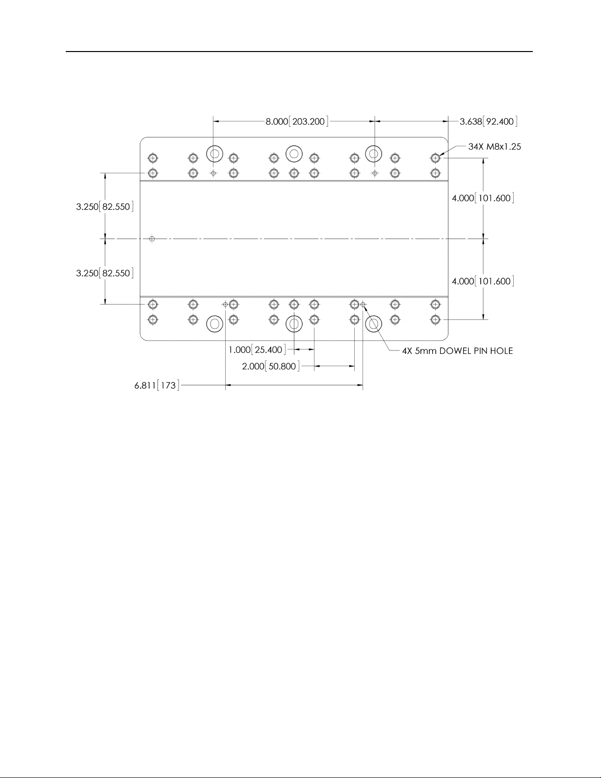
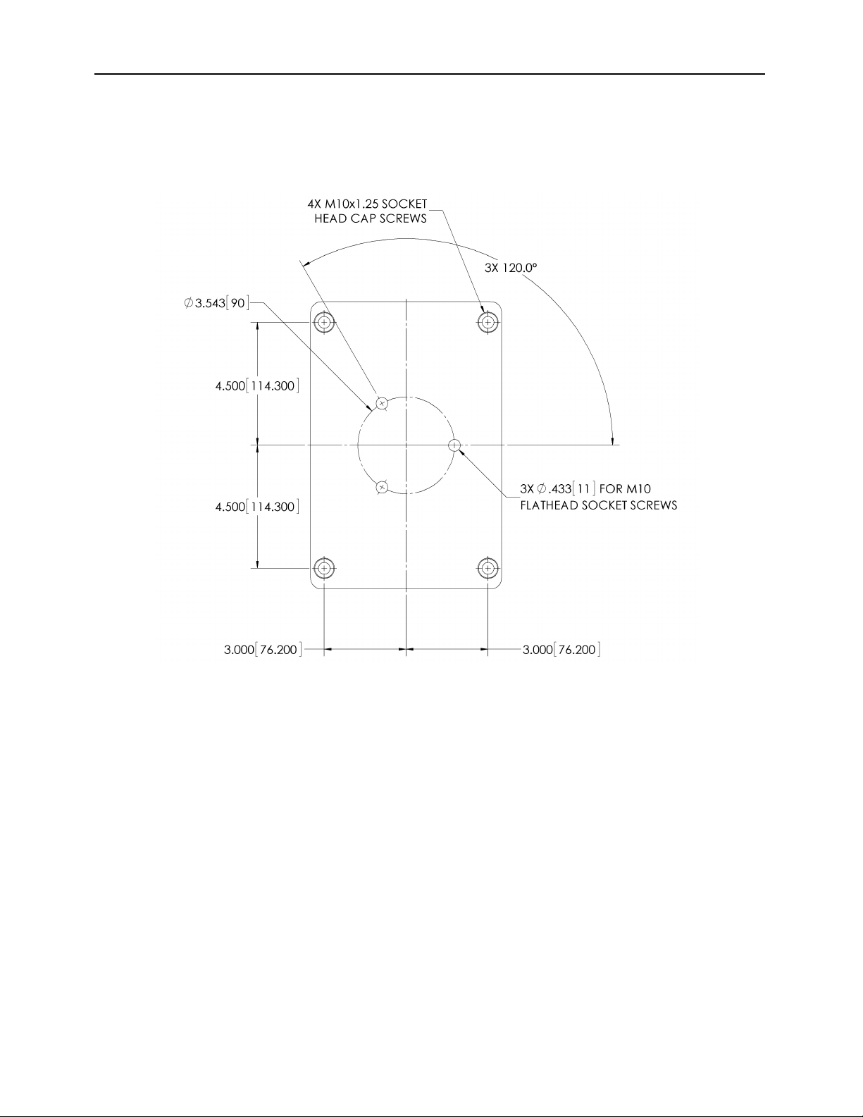
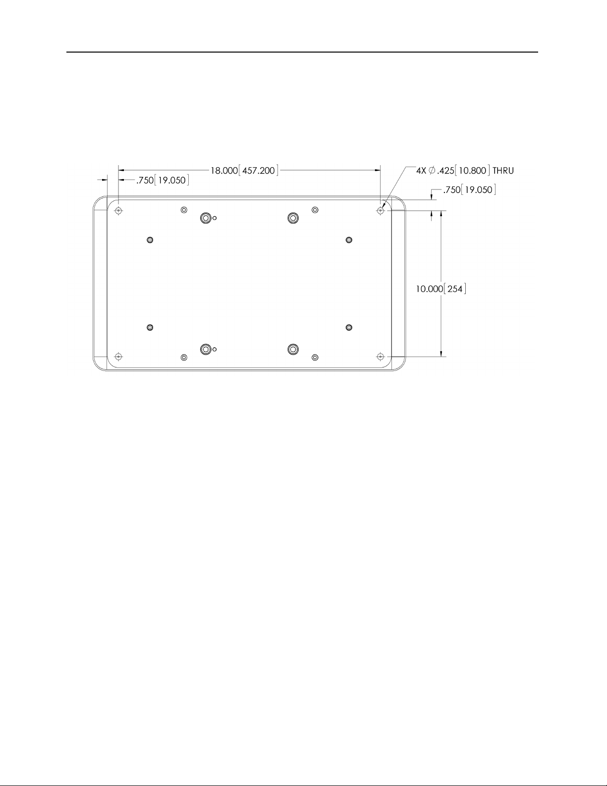
3.1 Mounting Process Equipment
T e AFD92 Adjustable Force Device can accommodate many different types of process
equipment. Pus Corp provides a variety of standard process equipment suc as weld
s avers, ig speed motors, belt sanders, and ot er specialized tooling. Users may
also develop process equipment for t eir own proprietary applications. T e AFD can be
oriented parallel or perpendicular to t e manipulator mounting flange, alt oug it is
important to note t at t e AFD can apply force only in t e direction of Carriage
translation.
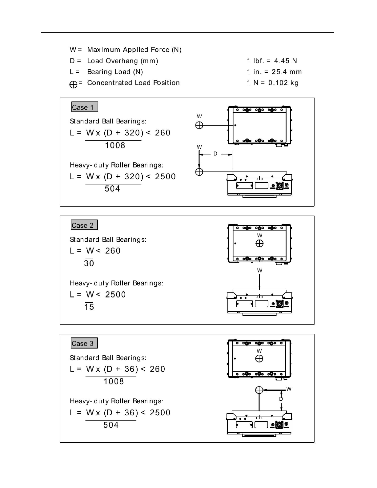
W en mounting process equipment to t e Carriage extreme care s ould be taken w ile
designing and installing t e brackets. Correctly designed brackets will increase t e
stiffness of t e Carriage by becoming an external superstructure for t e Carriage. T e
Carriage can gain a tremendous amount of rigidity if t is approac is executed correctly.
Incorrectly designed bracketry will deform t e Carriage causing internal Linear Rail
misalignment. A symptom of Carriage deformation is “slop” or “binding” of t e Carriage.
A deformed or loose Carriage will damage t e Linear Rails and degrade t e consistency
of your process. T e Carriage preload is correctly set at t e factory and s ould not
Copyrig t PushCorp, Inc. 2006. All rig ts reserved

PUSHCORP, INC.
AFD92 Manual 5
require adjustment. If t e Carriage becomes loose or binds after installing t e process
equipment, t en t e brackets must be removed and t e problem corrected. PushCorp,
Inc. can design and fabricate brackets to user supplied specifications as an option.
Figure 1. Carriage bolt ole pattern
T e bolt pattern on t e Carriage as been designed to facilitate process equipment
installation. T e Carriage as t irty-four (34) M8x1.25 mounting oles wit a dept of
0.52 inc (13 mm) to provide secure attac ment points. T e mounting oles are spaced
as s own in Figure 1. T e Carriage also as two (2) 5mm dowel pin oles to be used
for process equipment alignment. (See Figure 1 for location) T ese dowel pin oles are
oversized to allow t e pins to be glued into place using Loctite 609, or equivalent. DO
NOT press pins into the AFD Carriage, as this will damage the Linear Rails.
CAUTION: The Fastener Tightening Torque Specs chart in Section 7.0 should be
used to determine proper fastener length and torque. This is to prevent pull-out
of the Carriage helicoil inserts. Fasteners must not exceed a depth of 0.52 inches
(13 mm) into the Carriage as this could damage the Linear Rails.
3.2 Mounting the AFD92
T e design of t e AFD92 force device allows attac ment to a stationary table top fixture
or a robotic manipulator mounting flange. Specifying a -2 or -3 determines w ic
Mounting configuration is supplied. Adapter plates or "quick-c ange" attac ments can
be used as well for mounting. T e AFD92 as two (2) 6mm dowel pins pressed into t e
base for location and alignment of t e Mounting Bracket.
Copyrig t PushCorp, Inc. 2006. All rig ts reserved

PUSHCORP, INC.
AFD92 Manual 6
3.2.1 Mounting the Horizontal AFD92
T e AFD90-2 is supplied wit a standard Mounting Bracket s own in Figure 2. A
minimum of (3) t ree oles s ould be utilized to secure t e Mounting Bracket to t e
robot mounting flange.
Figure 2. AFD90-2 Mounting Bracket
If additional oles are required, it must first be removed from t e device before drilling.
Four (4) M10x1.5 Socket Head Cap Screws are used to attac t e Mounting Bracket to
t e AFD92 force device. Once t e Mounting Bracket is removed, mounting oles may
be placed anyw ere wit in t e cross atc ed area s own in Figure 2. PushCorp, Inc.
can supply engineering support to determine t e mounting ole locations at no cost.
After drilling t e required ole pattern, remove any burrs and clean any mac ining
residue from t e Mounting Bracket. T e Mounting Bracket dowel pin oles must be
aligned before it can t en be reattac ed. T e fasteners s ould be torqued to t e
specification in Section 7.0.
Copyrig t PushCorp, Inc. 2006. All rig ts reserved

PUSHCORP, INC.
AFD92 Manual 7
3.2.2 Mounting the Table Top AFD92
T e AFD90-3 is designed for mounting on a stationary fixture. It as four (4) 0.41”
(10.5 mm) mounting oles spaced as s own in Figure 3. T e AFD90-3 Table Top
Mounting Bracket s ould not be modified wit out first consulting Pus Corp, Inc. T e
surface t at t e Mounting Bracket is mounted to must be flat to avoid distorting t e
base.
Figure 3. AFD90-3 Mounting Bracket ole locations
3.3 Maximum Carriage Load Calculations
T e Linear Rail bearings t at support t e AFD92 Carriage ave been selected to
provide optimal performance wit respect to capacity, size, and low friction. To ensure
optimal performance it is very important not to overload t ese bearings. T e following
diagrams and associated equations are provided to c eck your application for excessive
loading.
It is important to note t at t ese equations require t e use of Metric units. T e
necessary unit conversions are provided for your convenience. Insert your maximum
applied force and process equipment weig t (W) and over ang distances (D) to
calculate an actual bearing load (L) t at must be less t an t e maximum bearing load
s own on t e rig t side of t e equation. T e life of t e bearings is 100,000 meters of
linear motion, at t e maximum allowable bearing load value. Exceeding t is value (L)
will reduce t e life, and operating at less t an t is value (L) will increase t e life. It is
common to ave combined weig t and force loads on t e Carriage. T ese situations
may require adding two or more of t e scenarios s own below. If your application is not
similar to any of t e designs listed ere, or if you are unsure of your application, please
contact PushCorp Tec nical Support for assistance. Ball-bearing equations apply to t e
standard AFD92. Roller-bearing equations apply to AFD92 ordered wit t e –HD,
Heavy-Duty option.
Copyrig t PushCorp, Inc. 2006. All rig ts reserved

PUSHCORP, INC.
AFD92 Manual 8
Copyrig t PushCorp, Inc. 2006. All rig ts reserved

PUSHCORP, INC.
AFD92 Manual 9
3.4 Pneumatic Connection
T e AFD92 Adjustable Force Devices require a dry, non-lubricated, 5 m filtered, 80 psi
(5.5 Bar) maximum air supply. Failure to provide supply air to t ese specifications can
degrade performance and will void any warranty repairs concerning pneumatic
components. Filtered air is required to prevent foreign material from entering t e AFD.
T e pneumatic supply system s ould be configured as s own in Figure 4.
Figure 4. Pneumatic configuration
To apply force in t e positive + direction, on an AFD91 or AFD92, a Supply Line must be
connected to t e + Supply Air Port. To apply force in t e negative - direction, on an
AFD92, a Supply Line must be connected to t e - Supply Air Port.
Copyrig t PushCorp, Inc. 2006. All rig ts reserved

PUSHCORP, INC.
AFD92 Manual 10
Figure 5. AFD92 air connections
If water condensation is a problem in your air supply system, an air dryer device is
ig ly recommended. T e ideal solution is an industrial c iller dryer capable of reducing
t e dewpoint to less t an 32 F (0C). Moisture inside t e AFD will cause premature
failure t at will not be covered under warranty.
In applications w ere t e environment contains suspended particulate matter purge air
flow must be used to ensure t at t e AFD remains clear of foreign matter. A Purge Port
on t e AFD92 (See Figure 5.) provides a pneumatic connection to supply t is air flow.
T e port accepts a metric R 1/8 tapered pneumatic fitting. Pus Corp provides fittings for
Englis or metric tubing. T e input pressure to t e purge port can range from 10 PSI to
60 PSI (0.7 – 4.1 bar) wit a flow rate of 0.5 to 2.0 SCFM (14 – 56 l/min) depending on
t e application. T e purge air must be dry and non-lubricated, owever it need only be
filtered to 20 microns.
T e Supply Line and Purge Line to t e device s ould be 1/4 inc or 6mm diameter
flexible polyuret ane tubing. T e tubing s ould be routed to t e AFD suc t at t ere are
no kinks and t at t ere is plenty of slack to allow for manipulator motion. Before
inserting t e Supply Line or Purge Line into t e force device air fitting, open t e S ut-Off
valve to blow out any contaminates w ic may be in t e line. T e tubing can now be
pus ed into t e self-locking fitting located on t e side of t e AFD. C arge t e Supply
Line wit compressed air and verify t at t ere are no air leaks.
NOTE: PushCorp highl recommends the use of flexible pol urethane tubing as
opposed to n lon tubing. This is because n lon tubing tends to crimp shut when
it is bent. This severel limits air flow to the AFD and causes instabilit .
To remove t e Supply Line, first disc arge all air pressure in t e system, t en w ile
pus ing inward on t e fitting's plastic ring, simultaneously pull t e tubing out. Cover or
plug t e self-locking fitting any time t e Supply Line or Purge Line is not connected.
T is will keep any contaminants from entering t e AFD.
3.5 Internal Air Cartridge Filter
T e AFD92 force device contains a Cartridge Filter in t e base ousing. T e Cartridge
Filter is designed to be t e last line of defense to protect t e AFD from contamination.
T e Cartridge Filter is not designed to be t e sole means of AFD supply air filtration.
T e pneumatic supply system must be configured as described in Section 3.4. If t e
filter becomes clogged t e AFD92 will not function properly. Replacement Cartridge
Filters may be purc ased from Pus Corp (Part No. PAR01943-1), or from t e
manufacturer directly (Parker, Part No. 050-05-DQ). To remove t e Cartridge Filter
loosen t e Cartridge Filter Holder located on t e side of t e AFD base ousing, See
Figure 5. Remove t e Cartridge Filter and perform a visual inspection. T e condition of
t e Cartridge Filter will give an indication of t e quality of your supply air system. Place
a new Cartridge Filter on t e Cartridge Filter Holder and insert it into t e AFD base
ousing. Tig ten t e Cartridge Filter Holder to a torque of 90 lb-in. (10.2 N-m).
Copyrig t PushCorp, Inc. 2006. All rig ts reserved

PUSHCORP, INC.
AFD92 Manual 11
4.0 Adjusting Carriage Preload
T e required preload on t e AFD92 Linear Rails as been set at t e factory for optimal
performance and, in general, s ould not require field adjustment. However, t ere are
situations t at could arise t at cause t e Linear Rails to need adjustment, or
replacement. Often a loose, or tig t, Carriage on a new AFD is indicative of an
improperly designed process equipment bracket. If t e problem disappears w en t e
brackets are removed t en t is is t e case. Normally t e Carriage will only require
adjustment after removal for field service.
To c eck for a loose Carriage, attempt to move t e Carriage in a lateral direction as
s own in Figure 6. If t e Carriage moves or seems to ex ibit any "slop", t en t e Linear
Rail preload must be readjusted. A dial indicator is elpful, but not necessary to
diagnose and correct a loose Carriage.
A Carriage t at is too tig t will require additional force to move. T is is often detected
during t e weig ting of t e process equipment mounted on t e Carriage. T e weig t
will be inconsistent, varying ig er or lower eac time t e process equipment is
weig ed.
Figure 6. Carriage preload adjustment
T e Linear Rails are attac ed to t e underside of t e Carriage wit (6) six M10x1.5
Socket Head Cap Screws. Located on t e side of t e Carriage are t e two Preload
Adjustment Set Screws used to translate t e Movable Linear Rail. Moving t e Linear
Rail associated wit t e Preload Adjustment Set Screws is all t at is necessary to adjust
t e Carriage preload.
Copyrig t PushCorp, Inc. 2006. All rig ts reserved

PUSHCORP, INC.
AFD92 Manual 12
To perform t e preload adjustment, follow t e procedure below:
1. C eck t e tig tness of t e (3) t ree Fixed Linear Rail M10x1.5 Socket Head
Cap Screws olding t e Fixed Linear Rail opposite t e Movable Linear Rail. If
t ese fasteners are loose t en t e Fixed Linear Rail must be seated against
t e flange inside t e Carriage. To do t is, loosen all (6) six fasteners located
on t e face of t e Carriage just enoug to allow t e Linear Rails to move.
Next tig ten t e Preload Adjustment Set Screws to force t e Fixed Linear Rail
to seat against t e flange. Tig ten t e (3) t ree Fixed Linear Rail M10x1.5
Socket Head Cap Screws, w ic old t e Fixed Linear Rail, to t e torque
specified in Section 7.0. T e Fixed Linear Rail is now correctly seated and t e
Preload Adjustment Set Screws can be loosened. You are now ready to
continue on to preload t e Carriage Linear Rails.
2. To preload t e Carriage Linear Rails, loosen t e Movable Linear Rail M10x1.5
Socket Head Cap Screws olding t e Movable Linear Rail only enoug to allow
t e rail to move relative to t e inside Carriage surface. T e Carriage as
slotted oles on t e Movable Linear Rail side w ic allow t e rail to move in
t e same direction as t e Preload Adjustment Set Screws. Make sure t at t e
Movable Linear Rail M10x1.5 Socket Head Cap Screws are loose before
attempting to set t e preload.
3. On a level surface, elevate t e positive end of t e AFD to approximately 4
(T is is roug ly t e angle t e AFD is at w en all t e cover and mounting plates
are removed and t e AFD is resting on t e mounting plate locating pins). Wit
t e Preload Adjustment Set Screws loose, gravity will pull t e carriage back
down to its negative stops after t e Carriage is pus ed up to its positive stops
and released. Begin to tig ten t e Preload Adjustment Set Screws evenly ⅛
turn eac , c eck t e preload periodically by pus ing t e carriage up to t e
positive stops and releasing it. As soon as gravity fails to return t e Carriage
to its negative stops, stop tig tening t e Preload Adjustment Set Screws.
Loosen eac Preload Adjustment Set Screw 1/16 turn, gravity s ould return
t e Carriage to its negative stops. It is possible t at one Preload Adjustment
set screw may need tig tening and t e ot er loosening. T e Carriage preload
s ould now be correct. If t e adjustment cannot be performed, contact t e
factory service center for assistance.
5. Verify t at gravity returns t e Carriage to its negative stops after begin pus ed
up to its positive stops and released, tig ten t e (3) t ree Movable Linear Rail
M10x1.5 Socket Head Cap Screws on t e Moveable Rail side to t e torque
specified in Section 7.0.
Copyrig t PushCorp, Inc. 2006. All rig ts reserved

PUSHCORP, INC.
AFD92 Manual 13
5.0 Electrical Connections
5.1 Carriage Position Feedback Connection
T e AFDAFD92 comes equipped wit an internal potentiometer t at provides a voltage
signal based on t e linear position of t e Carriage. T e voltage signal is at a minimum
w en t e Carriage is in t e full negative position and a maximum w en t e Carriage is in
a full positive position. A Hig -Flex Cable is used to connect t e DC supply, and analog
signals to t e force device. T e connector is specially designed to minimize strain on
t e cable. T e plug and socket is configured to make it impossible to connect t em
incorrectly.
T e linear position signal must be calibrated for eac installation. User calibration is
easily accomplis ed using t e following steps.
1. Attac t e Hig -Flex Cable to t e Carriage Position Feedback Connector.
2. Attac t e Hig -Flex Cable wires as s own in Figure 7.
3. Move t e Carriage to t e full negative position.
4. Read t e voltage signal on t e POSN Posi ion Signal output. Record t is
voltage for future reference. T is will be referred to as Vneg.
5. Move t e Carriage to t e full positive position.
6. Read t e voltage signal on t e POSN Posi ion Signal output. Record t is
voltage for future reference. T is will be referred to as Vpos.
7. T e position of t e Carriage can now be determined by measuring t e current
voltage on t e POSN Posi ion Signal output (Vm) and inserting t e value into t e
following equation:
W ere,
mm)inch(sitionarriage popositive C at fully ed voltage= CalibratV
mm)inch(tionriage posigative Cart fully ne voltage aCalibratedV
re (V) signal wiPOSNasured on Voltage meVm
mm)inPosition ( Carriagep
pos
neg
40,6.1,
0,0,
,
Copyrig t PushCorp, Inc. 2006. All rig ts reserved

PUSHCORP, INC.
AFD92 Manual 14
Figure 7. Electrical Connections
Supply Vol age - T e supply voltage input for t e AFD92. T e supply s ould
be well regulated to +/- 10%. T e load resistance is 3000 30%. T e
supply voltage s ould not exceed 24VDC. A 12VDC supply will yield a
POSN signal output voltage between 0 and 10VDC.
Supply Common - T e supply common input for t e AFD92. It s ould be
connected to t e common terminal for t e supply as well as t e analog
common for t e position signal.
Posi ion Signal - T e linear potentiometer signal output. T is voltage signal
represents t e Carriage position. T e device connected to t is output s ould
ave an input impedance of equal to or greater t an 100k. T e linear
potentiometer signal is not calibrated from t e factory but is linear to 1.0%.
Cable Shield – T e drain wire for t e overall cable s ield. Connect t is wire
to t e central grounding point of t e panel.
Copyrig t PushCorp, Inc. 2006. All rig ts reserved
COM
+V
POSN
SHLD

PUSHCORP, INC.
AFD92 Manual 15
Figure 8. Linear Potentiometer Signal Connection
NOTE: Care should be taken to ensure that all signal and voltage source
commons are connected together on the user end to avoid D.C. offset errors.
6.0 Achieving Desired Force
6.0.1 Table Top
T e AFD92 is a passive force device t at requires t e user to provide pressure to t e
pneumatic actuators. Pressure in t e actuators results in an output force at t e
Carriage. If t e AFD is a table top unit, and/or always in t e orizontal position or does
not c ange orientation ac ieving t e desired output force is easy. T e passive force
device requires t e user to provide regulated air pressure to ac ieve a desired force
output. Use t e following equations for a table top unit to determine t e pressure
required to ac ieve t e desired output force:
units Metric )166(
unitsEnglish )6.2(
sam
sa
PF
PF
W ere:
bar)or (psi pressureSupply
(N) force applie AFDNet
(lbs.) force applie AFDNet
s
am
a
P
F
F
Copyrig t PushCorp, Inc. 2006. All rig ts reserved

PUSHCORP, INC.
AFD92 Manual 16
6.0.2 Wrist Mount
If t e AFD92 is not always orizontal and c anges orientation, t en two system
variables ave to be considered w en ac ieving a desired output force: t e Process
Equipment Weig t carried by t e AFD and t e angle of t e Carriage wit respect to
gravity. T e angle of t e Carriage must be known so t at t e Process Equipment
Weig t can be compensated for. T e Process Equipment Weig t includes t e AFD
Carriage weig t. T is value can be back calculated from t e area and pressure in t e
pneumatic actuator. T e best met od to determine t e Process Equipment Weig t is
wit a calibrated load cell. T e angle of t e Carriage to t e gravity vector is defined as
s own below in Figure 9.
Figure 9. Definition of t e carriage angle.
T e AFD92 is available in two configurations, t e AFD91, and t e AFD92. T e AFD91
as a pair of single-acting pneumatic actuators, so it may only apply positive forces.
T e AFD92 as two pairs of single-acting actuators acting in opposite directions. T is
allows t e AFD92 to apply bot positive and negative forces. T e area of t e pair of
cylinders is 2.6 in2 (1677 mm2) so, for every 1.0 psi (0.07 bar) of supply pressure t e
AFD applies 2.6 lbs. (166 N/Bar) of force. T is makes t e AFD92 very easy to setup.
To apply a 40 lbs. (178 N) force just set t e supply pressure to 15.4 psi (1.1 Bar). T is,
owever, does require t e user to supply one (t e AFD92 requires two) precision
pressure regulator to accurately adjust t e applied force. T e pressure regulator may
be eit er manually or electrically controlled. Electrically controlled regulators are
normally t e proportional type, w ic outputs a pressure t at is scaled to a voltage input.
T e force output repeatability and resolution is directly related to t e quality of t e
pneumatic regulator.
Copyrig t PushCorp, Inc. 2006. All rig ts reserved

PUSHCORP, INC.
AFD92 Manual 17
T e following are equations defining t e applied force from eac of t e AFD92.
AFD91 (Single Acting) Applied Force:
units Metric )cos()5.8(81.9)166(
unitsEnglish )cos()7.18()6.2(
WPF
WPF
sam
sa
W ere:
9) Figure (Seegravity torelative angle Carriage
kg)or (lbs.Weight Equipment Process
bar)or (psi pressureSupply
(N) force applie AFDNet
(lbs.) force applie AFDNet
W
P
F
F
s
am
a
AFD92 (Double Acting) Applied Force:
units Metric )cos()5.8(81.9
unitsEnglish )cos()7.18(
WFFF
WFFF
nmpmam
npa
W ere:
9) Figure (Seegravity torelative angle Carriage
kg)or (lbs.Weight Equipment Process
bar)or (psi pressuresupply si e Negative
bar)or (psi pressuresupply si e Positive
(N) )166(irection negativein Force
(N) )166(irection positivein Force
(lbs.) )6.2(irection negativein Force
(lbs.) )6.2(irection positivein Force
(N) force applie AFDNet
(lbs.) force applie AFDNet
W
P
P
PF
PF
PF
PF
F
F
sn
sp
snnm
sppm
snn
spp
am
a
Copyrig t PushCorp, Inc. 2006. All rig ts reserved

PUSHCORP, INC.
AFD92 Manual 18
7.0 Technical Specifications
Maximum Applied Force: 250 lbs. (222 N)
Maximum Payload: 200 lbs. (90 kg) of Process Equipment
Weig t: AFD90-2 56 lbs. (26 kg)
AFD90-3 56 lbs. (26 kg)
Force Scale Factor: 2.6 lbs/psi (166 N/bar)
Compliant Stroke: 1.4 in. (36 mm)
Temperature: 50 to 122 F (10 to 50 C)
Humidity: 5% to 95%, Non-Condensing
Supply air: Non-lubricated, Dry, 5µm Filtered, 90 psi (6.2 bar) Max.
Specifica ions subjec o change wi hou no ice.
Fastener Tightening Torque Specs
Torque Minimum Dept
Fastener Size in.-lbs. ft.-lbs. N·m in. mm
M4 x .7 50 4.2 5.6 0.17 4.3
M5 x .8 85 7.1 9.6 0.21 5.3
M6 x 1 140 11.7 15.8 0.25 6.3
M8 x 1.25 348 29.0 39.3 0.33 8.4
M10 x 1.5 600 50.0 67.8 0.41 10.5
Copyrig t PushCorp, Inc. 2006. All rig ts reserved
Table of contents
Other PushCorp Industrial Equipment manuals

PushCorp
PushCorp SBS81 Series User manual

PushCorp
PushCorp AFD310 User manual

PushCorp
PushCorp AFD1200 User manual

PushCorp
PushCorp AFD1240 User manual

PushCorp
PushCorp 620 Series User manual

PushCorp
PushCorp SWS100-3.7 User manual

PushCorp
PushCorp AFD1000 Series User manual

PushCorp
PushCorp RPC100-75 User manual