PushCorp SWS100-3.7 User manual

Series Servo
Weld Shavers
SWS100-3.7/7.2
User Manual
PUSHCORP, INC.
Dallas, Texas

! DANGER !
REMOVE SERVO MOTOR
ELECTRICAL POWER
before re lacing Slot Cutter inserts
or servicing weld shaver.
! WARNING !
SAFETY GLASSES ARE ALWAYS
REQUIRED
Insert breakage or shatter resents
great otential for eye injury.
All PushCorp, Inc. electrical cables are rated for
high twist and flex robotic a lications with a
minimum cable bending radius s ecification of
125mm (5 in). Cable damage resulting from
failure to abide by this s ecification will not be
covered under warranty.

PushCorp, Inc. SWS100 Series Weld Shavers
Table of Contents
1.0 LIMITED WARRANTY...................................................................................................1
2.0 GENERAL OVERVIEW..................................................................................................3
3.0 INSTALLATION.............................................................................................................4
3.1 MOUNTING THE SWS100.................................................................................................................. 4
3.2 ELECTRICAL CONNECTIONS.......................................................................................................... 5
4.0 OPERATION..................................................................................................................6
4.1 KOLLMORGEN MOTOR.................................................................................................................... 6
4.2 SETTING THE DEPTH OF CUT......................................................................................................... 6
4.2.1 MANUALLY SETTING THE DEPTH OF CUT.................................................................................7
4.2.2 REMOTELY SETTING THE DEPTH OF CUT.................................................................................8
4.3 SETTING FEEDS AND SPEEDS........................................................................................................ 8
4.4 PROBLEMS AND CORRECTIVE MEASURES..................................................................................9
4.5 TEACHING THE WELD SHAVER PATH...........................................................................................9
5.0 SLOT CUTTER AND INSERTS...................................................................................10
6.0 SPECIFICATIONS.......................................................................................................12
6.1 SWS100-3.7 SPECIFICATION..........................................................................................................12
6.2 SWS100-7.2 SPECIFICATIONS.......................................................................................................13
Copyright © PushCorp, Inc. 2010. All rights reserved.

1.0 Limited Warranty
Duration:
One year from date of delivery to the original purchaser.
Who gives this warranty (warrantor):
PushCorp, Inc.
Telephone: (97 ) 840-0 08
Corporate Address:
P. O. Box 181915
Dallas, Texas 75 18
Shipping Address:
3001 W. Kingsley Rd.
Garland, Texas 75041
Who receives this warranty ( urchaser):
The original purchaser (other than for purposes of resale) of the PushCorp, Inc.
product
What roducts are covered by this warranty:
Any PushCorp, Inc. industrial equipment or accessory supplied or manufactured
by the Warrantor.
What is covered under this warranty:
Defects in material and/or workmanship which occur within the duration of the
warranty period.
What is NOT covered in this warranty:
A. IMPLIED WARRANTIES, INCLUDING THOSE OF MERCHANT-ABILITY AND
FITNESS FOR A PARTICULAR PURPOSE ARE LIMITED TO ONE YEAR
FROM THE DATE OF ORIGINAL PURCHASE. Some states do not allow
limitations on how long an implied warranty lasts, so the above limitations may
not apply to you.
B. ANY INCIDENTAL, INDIRECT, OR CONSEQUENTIAL LOSS, DAMAGE or
EXPENSE THAT MAY RESULT FROM ANY DEFECT, FAILURE,
MALFUNCTION OF THE PUSHCORP, INC. PRODUCT. Some states do not
allow the exclusion or limitation of incidental or consequential damages so the
above limitation or exclusion may not apply to you.
C. Any failure that results from an accident, purchaser's abuse, neglect,
unauthorized repair or failure to operate the products in accordance with the
instructions provided in the owner's manual(s) supplied with the product.
Res onsibilities of the Warrantor under this warranty:
Repair or replace, at Warrantor's option, products or components which have
failed within the duration of the warranty period.
January, 0 1

Res onsibilities of the urchaser under this warranty:
A. Deliver or ship the PushCorp, Inc. product or component to PushCorp, Inc.
Service Center, 3001 Kingsley Rd., Garland, TX 75041. Freight and
insurance costs, if any, must be borne by the purchaser.
B. Use reasonable care in the operation and maintenance of the product as
described in the owner's manual(s).
When warrantor will erform re air or re lacement under this warranty:
Repair or replacement will be scheduled and serviced according to the normal
work flow at the service center, and depending on the availability of replacement
parts. Purchasers requiring quicker repair may receive such with payment of a
PushCorp, Inc. predetermined expediting fee.
This Limited Warranty gives you specific legal rights and you may also have other rights
which vary from state to state.
January, 0

2.0 General Overview
The PushCorp, Inc. SWS100 Series Servo Weld Shaver provides a fast and effective
means to accurately remove excess material from a surface. The Weld Shaver is
designed to remove random, inconsistent surface features such as seam welds, parting
lines, and flashing, leaving behind a known, consistent, smooth surface. The SWS100 is
ideal for use in applications where force-based, abrasive-only operations fail. Using the
SWS100 can produce significant cost savings since one set of inserts can often out last
hundreds of abrasive disks. A large selection of replaceable Carbide cutting inserts are
used to literally peel metal away. The Weld Shaver/AFD combination forms a unique
system where force control and positioning are used to perform accurate machining
operations with a robot.
The SWS100 enables accurate surface machining by utilizing Tracking Wheels to follow
over the part surface profile. An appropriate Adjustable Force Device is used to hold the
Tracking Wheels firmly against the part surface. This arrangement allows the Weld
Shaver to maintain contact with complex surfaces while compensating for any robot/part
misalignment.
The SWS100 is comprised of two primary components: a Slot Cutter assembly, and a
high torque Servo Motor. PushCorp offers two variations of weld shavers differentiated
by their horsepower: 3.7HP and 7. HP; the overall structure of the two variations are
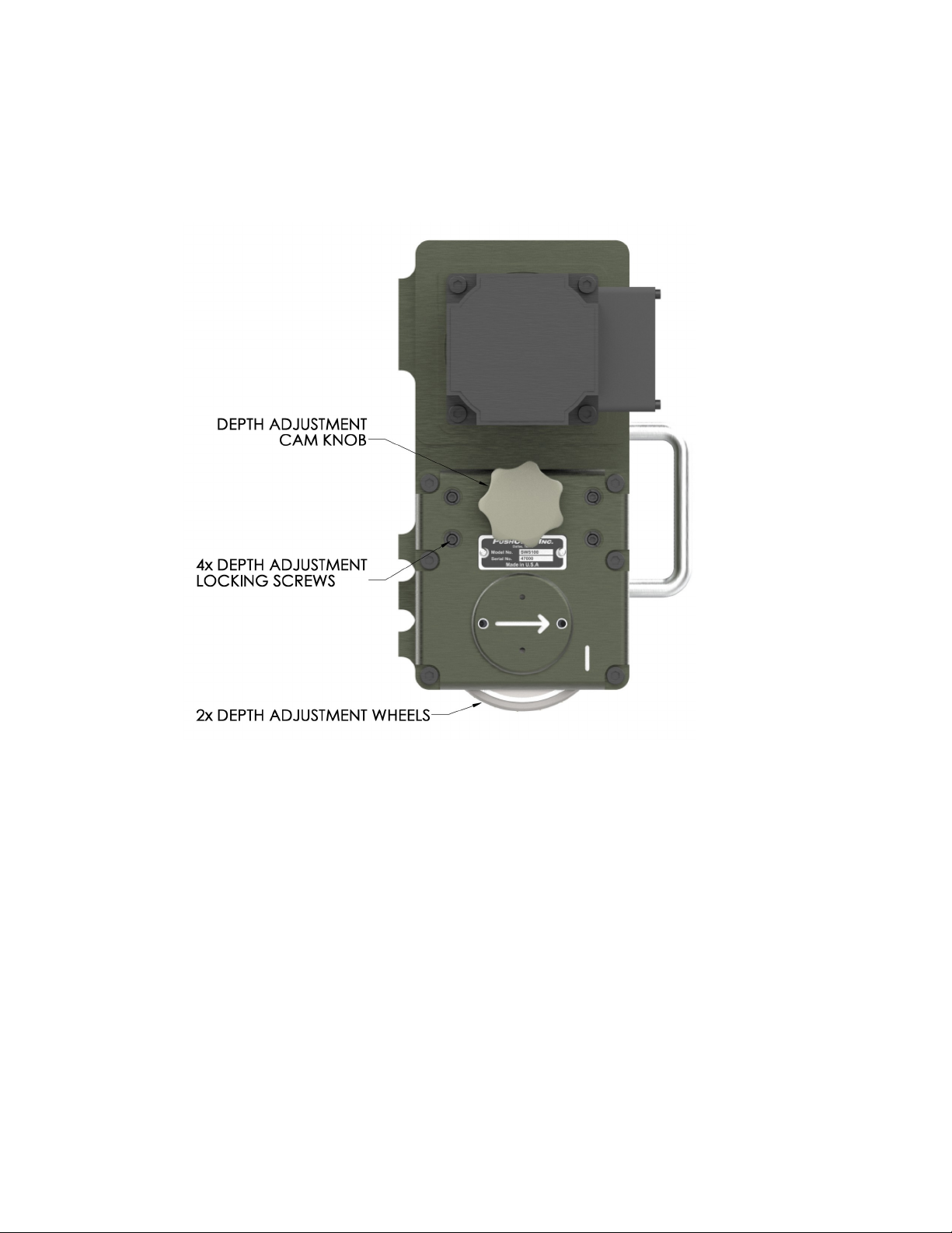
similar and only differ in height and torque. For each variation of shaver, PushCorp offers
a manually and remote method of adjusting the cutter height relative to the parent
material.
The machining operation is performed by a 5 inch (1 5mm) diameter Sandvik Coromill®
331 Slot Cutter with replaceable Cutter Inserts. Each Slot Cutter is capable of machining
a 0mm wide path. The SWS100 Series Weld Shavers may be configured with one, two,
or three Slot Cutters allowing a width of cut ranging from 0mm to 59mm. The cutting
depth of the Slot Cutter can be adjusted to any position from 0.1 inch ( .5mm) above the
surrounding part surface to 0.1 inch ( .5mm) below.
A Servo Motor provides the power to turn the Slot Cutter, and allows precision adjustable
speed control through a 0-10VDC analog interface. The SWS100-3.7 Series uses a 3.7
Horsepower motor with a speed range of 0 to 4 00 RPM; the SWS100-7. Series uses a
7. Horsepower motor with a speed range of 0 to 500 RPM. The belt and pulley drive
provides a 1.5:1 reduction ratio for the SWS3.7, and a 1.3:1 reduction ratio for the
SWS7. ; this reduction reduces the speed and increases the output torque at the Slot
Cutter. The Servo Motor allows the Weld Shaver to control Slot Cutter speed within 5%.
The projected life of this high quality Servo Motor is over 30,000 hours.
Simple reliable construction combined with high torque, precision speed controlled servo
technology make the PushCorp SWS100 Servo Weld Shaver a rugged, state-of-the-art
technology capable of providing flexible, cost-effective weld machining operations.
January, 0 3

3.0 Installation
3.1 Mounting the SWS100
The SWS100 Series Weld Shavers are designed to attached to the carriage of a
PushCorp AFD80/90 via a mounting plate. Refer to Figure 1 for proper component stack
up.
The SWS100 attaches to the mounting plate with 3x M6x1x 0 flange-head fasteners
provided by PushCorp. The mounting plate can then be mounted to the AFD carriage via
January, 0 4
Figure 1.Mounting the SWS100- 0,
SWS100-39, and SWS100-59

4x M8x1. 5x 0 flange-head fasteners. If necessary, the Adapter Plate can be extended
beyond the end of the carriage to allow for more clearance.
CAUTION: If alternate fasteners are used make sure they do not exceed a de th of
0.525 inch (13.3 mm) into the AFD Carriage or damage can occur.
3.2 Electrical Connections
To use the SWS100 Series Weld Shavers it is necessary to connect the Servo Power,
and Servo Feedback cables correctly. The servo amplifier is pre-configured to accept a
0 – 10VDC analog command velocity signal and a 4VDC digital signal to enable the
motor. These are the only two signals that are required for operation and no other
configuration is required to operate the motor. Other more advanced features are
available and may be configured by referring to the supplied servo amplifier
documentation on the PushCorp website.
If utilizing a raw s7 4 amplifier, please refer to Products → Kollmorgen S7 4
January, 0 5

4.0 O eration
4.1 Kollmorgen Motor
PushCorp provides both a 3.7HP and a 7. HP version of weld shaver. The SWS100-3.7
has a speed range of 0-4 00 RPM, and the SWS100-7. has a speed range of 0- 500
RPM There are 00 steps per full revolution both the 3.7HP and 7. HP motors. The belt
pulley drive provides a 1.5:1 reduction ratio for the SWS100-3.7 and a 1.3:1 reduction
ratio for the SWS100-7. .
4.2 Setting the De th of Cut
PushCorp provides two methods for adjusting the cutting depth of the weld shaver.
Based on the unit you have this operation can be done remotely via a stepper motor or
manually with a cam knob. Adjusting the weld shaver’s depth of cut is accomplished by
raising or lowering the adjustment depth wheels. Raising the depth wheels to the
maximum position will result in a cut approximately 0.1 inch ( .5mm) below the parent
material. Lowering the depth wheels to their lowest position will set the cutting inserts
approximately 0.1 inch ( .5mm) above the parent material. Both of these examples
assume the surface is flat and these depths would be different if the surface is curved.
CAUTION: Remove all ower from the Servo Motor before erforming any
adjustments to the SWS100 Series Weld Shaver.
4.2.1 Manually Setting the De th of Cut
January, 0 6
Figure : Depth Wheel Extended & Retracted

To manually adjust the depth of cut, first loosen the four (4) Depth Adjustment Locking
Screws approximately 1/4 turn shown in Figure 3.
CAUTION: It is required that the De th Adjustment Locking Screws are released
before the De th Adjustment Knob is rotated. Failure to release the De th
Adjustment Locking Screws can damage the mechanism and require the unit to be
returned to the factory service center for a non-warrant re air.
Rotate the depth adjustment cam knob to move the depth adjustment wheels relative to
the slot cutter. Rotating the depth adjustment knob one complete revolution will result in
the Tracking Wheels moving 0. inches (5mm). A straight edge can be placed on the
depth adjustment wheels to position the cutter inserts to cut flush with the surface. In
other cases it is most expeditious to approximate the initial setting and fine tune the
Tracking Wheel position with sample passes. Once a depth-of-cut has been selected,
the four (4) M8 Depth Adjustment Locking Screws should be re-tightened to the torque
specified in Section 7.0 before beginning machining operations.
4.2.2 Remotely Setting the De th of Cut
January, 0 7
Figure 3. Depth-of-cut Adjustment

To remotely set the depth of cut, connect the SWS100 Remote Adjust to the stepper
motor amp via the appropriate control cable. Refer to 4 for proper cable pin out.
This will allow you to adjust the wheels up and down using a robot controller or PLC. The
stepper motor for both the SWS100-3.7 and SWS100-7. has a single step of 1.8
degrees and a total of 00 steps for a full revolution. This translates to a 06 5” (1.59mm)
height change for a full rotation and .0003”/step (0.008mm/step). The remote adjust
weld shaver amp does not utilize a built-in position feedback. As a result, the following
steps can be used to zero the position.
1. Position the weld shaver above the parent material
. Apply 5V to the direction pin to fully extend the depth adjustment wheels.
3. Once in position, reset the step counter (on your PLC or robot controller) to zero
4. Keep track of the number and direction of steps is required to keep track of the
depth adjustment wheel location
If more accurate positional data is required, an alternative method is to utilize an optical
sensor in the workcell and step the motor to make/break the beam to know its location.
4.3 Setting Feeds and S eeds
January, 0 8
Figure 4: Remote Depth of Cut Adjustment

Speed and Feed are important factors to consider for best results in milling. Improper
Feed and Speed often cause low production, poor work quality and unnecessary wear to
the inserts. In milling, Cutter Speed is measured in peripheral feet per minute,
(revolutions per minute times the Slot Cutter circumference in feet). Every application
and material will have different cutter speeds and feedrates. It will be up to the end user
to dial in both parameters based on their application. Section 4.3 outlines some of the
corrective actions that can be taken to help determine these values more quickly.
4.4 Problems and Corrective Measures
Table shows some of the more common troubles encountered and the recommended
corrective measures involving variations in Cutter Speeds (Servo Motor RPM) and Feeds
(Robot Feed Rate).
Problem Corrective Action
Lack of rigidity (Robot Flexing) Increase Cutting Speed, reduce Feed
Excessive abrasion on the insert Reduce Cutting Speed, increase Feed
Chipping of the cutting edge Reduce Feed/Cutter Insert
Burning of the cutting edge Reduce Cutting Speed
Cratering of cemented carbide Reduce Feed and Cutting Speed
Chatter Try other combinations of Feed and Cutting Speed
Table . Troubles and Corrective Measures
4.5 Teaching the Weld Shaver Path
Teaching the path over the part surface is greatly simplified because of the force device’s
compliance. The force control carriage stroke of the AFD allows the Weld Shaver Guide
Wheels to easily maintain consistent contact with the part surface. Both Guide Wheels
must maintain continuous contact with the art surface during the machining
o eration.
The required AFD force is dependent on the application, however a 0 lbs. (89 N)
applied force is usually a good starting point. If the force is too low, the Guide Wheels
can rise from the surface and cause damage to the cutter inserts. Conversely, applying
too much force can cause the part surface to deflect or deform and places unnecessary
loads on the Guide Wheels.
The Guide Wheels should straddle the weld seam to produce the best results.
Remember, the Weld Shaver only follows the part surface. Therefore any dirt,
contamination, or weld spatter will affect the final quality of the cut.
January, 0 9

5.0 Slot Cutter and Inserts
The Slot Cutter provides for Cutter Insert location plus adjustable width and indexing
capabilities. The Cutter Inserts are retained securely in position by Insert Screws which
permit the Cutter Inserts to be “indexed”. A large selection of Cutter Inserts are available
from Sandvik.
Item Sandvik Part Number Description
1 RIGHT 53 1 40-07 RIGHT CASSETTE
1 LEFT 53 1 40-08 LEFT CASSETTE
5513 0 0- 9 INSERT SCREW
3 USER SELECTED CUTTER INSERT
4 5431 105-04 WEDGE
5 339-831 WEDGE SCREW
January, 0 10
Figure 5. Slot Cutter Assembly

DANGER: Remove all ower from the Servo Motor before changing or indexing
Cutter Inserts.
WARNING: Insure Wedge Screws are securely tightened into the Slot Cutter,
before rotating with the Servo Motor.
Set u Procedure
1. Determine the correct insert for the material to be milled.
. Remove the Insert Screw ( ) shown in Figure 5 and install or index the dull
Cutter Insert.
3. Insure that the Slot Cutter is Cassette Pocket (1) is clean.
4. Hand position the Cutter Insert (3) between in the Cassette.
5. Securely tighten the Insert Screw ( ) with a torque of 6 lb.- in. (3 N·m).
The Insert Screw is a type orx Plus 15IP. The recommended Sandvik torque
wrench is listed below.
6. Continue this process until all (8) eight Cutter Inserts are replaced or
correctly indexed.
NOTE: Cutter Inserts can be indexed (i.e., rotated) 180.
Cutter Insert Screw torque wrench:
Sandvik P/N: 5680 100-06 (Torx Plus)
Wedge Screw Key:
Sandvik P/N: 65. -817 (3.0mm)
Cutter Inserts:
Sandvik ordering code: N331.1A-11 50
January, 0 11

6.0 S ecifications
6.1 SWS100-3.7 S ecification
TOOL WEIGHT:
SWS100-3.7- 0: 45 lbs. ( 0.5 kg)
SWS100-3.7-39: 5 lbs. ( 3.6 kg)
SWS100-3.7-59: 60 lbs. ( 7.3 kg)
MOTOR SPECIFICATIONS:
Power: 4.8 Hp (3.6 kW)
Continuous Cutter Torque: 15.6 lb-ft (14.7 N·m)
Maximum Motor RPM: 4 00 RPM
Motor to Cutter Belt Ratio: 1.5:1
Supply Voltage: 08-480 VAC, 3Ф, 50 / 60 Hz
Drive Belt Specification: Gates P/N 8MGT-640- 1
Requires separate power supply, amplifier and cables.
CUTTER SPECIFICATIONS:
Manufacturer: Sandvik 331 Coromill
Insert Size: 11
Insert Style: N331.1A-11 50
Diameter: 4.9 inch (1 5mm)
No. Inserts: 8
Cutting Width: 0mm, 39mm, 59mm
For specific dimensions see htt ://www. ushcor .com for detail drawings.
Specifications subject to change without notice.
January, 0 1

6.2 SWS100-7.2 S ecifications
TOOL WEIGHT:
SWS100-7. - 0: 61 lbs. ( 7.7 kg)
SWS100-7. -39: 68 lbs. (30.9 kg)
SWS100-7. -59: 76 lbs. (34.5 kg)
MOTOR SPECIFICATIONS:
Power: 8.4 Hp (6. 4 kW)
Continuous Cutter Torque: 18.1 lb-ft ( 4.5 N·m)
Maximum Motor RPM: 500 RPM
Motor to Cutter Belt Ratio: 1.3:1
Supply Voltage: 480 VAC, 3Ф, 50 / 60 Hz
Drive Belt Specification: Gates P/N 8MGT-7 0- 1
Requires separate power supply, amplifier and cables.
CUTTER SPECIFICATIONS:
Manufacturer: Sandvik 331 Coromill
Insert Size: 11
Insert Style: N331.1A-11 50
Diameter: 4.9 inch (1 5mm)
No. Inserts: 8
Cutting Width: 0mm, 39mm, 59mm
For specific dimensions see htt ://www. ushcor .com for detail drawings.
Specifications subject to change without notice.
Fastener Tightening Torque S ecs
Torque Minimum Depth
Fastener Size in.-lbs. ft.-lbs. N·m in. mm
M4 x .7 50 4. 5.6 0.17 4.3
M5 x .8 85 7.1 9.6 0. 1 5.3
M6 x 1 140 11.7 15.8 0. 5 6.3
M8 x 1. 5 348 9.0 39.3 0.33 8.4
M10 x 1.5 600 50.0 67.8 0.41 10.5
January, 0 13
This manual suits for next models
1
Table of contents
Other PushCorp Industrial Equipment manuals

PushCorp
PushCorp AFD310 User manual

PushCorp
PushCorp AFD1200 User manual

PushCorp
PushCorp AFD1000 Series User manual

PushCorp
PushCorp AFD92 User manual

PushCorp
PushCorp AFD1240 User manual

PushCorp
PushCorp 620 Series User manual

PushCorp
PushCorp RPC100-75 User manual

PushCorp
PushCorp SBS81 Series User manual
Popular Industrial Equipment manuals by other brands

Agilent Technologies
Agilent Technologies E444 AU Series installation guide

Frucosol
Frucosol MC500 user manual

BOOTDOC
BOOTDOC ULTRACAM UP operating manual

Schmalz
Schmalz SCPi FS RP operating instructions

Kyocera
Kyocera C100 instruction manual

PCB Piezotronics
PCB Piezotronics M1630-03C Installation and operating manual