PXM PX156 User manual

User manual

1 Description...................................................................................................4
2 Safety conditions........................................................................................5
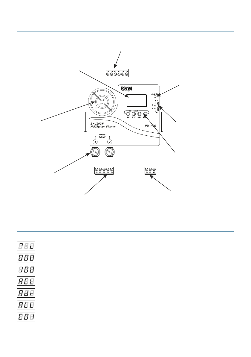
3 Connectors and control elements...........................................................7
4 Designation of displayed messages.......................................................7
5 Dimmer programming...............................................................................9
6 Programmable parameters......................................................................9
6.1 Digital inp t settings................................................................................................10
6.1.1 Group parameters............................................................................................11
6.1.2 Individual parameters......................................................................................12
6.1.3 Temperature...................................................................................................... 13
6.1.4 Input control mode..........................................................................................13
6.1.5 Scenes and chaser programming.................................................................13
6.2 Analog inp t settings...............................................................................................14
6.2.1 Group parameters............................................................................................14
6.2.2 Individual parameters......................................................................................15
6.2.3 Temperature...................................................................................................... 16
6.2.4 Input mode........................................................................................................ 16
6.3 F nction diagrams for external b tton control...................................................17
6.3.1 Function one.....................................................................................................17
6.3.2 Function t o..................................................................................................... 17
6.3.3 Function three...................................................................................................18
6.3.4 Function four....................................................................................................18
6.3.5 Function #ve.....................................................................................................19
7 Dimmer access lock................................................................................20
7.1 Switching the access lock on.................................................................................21
7.2 Switching the access lock off................................................................................21
8 Men scheme for digital inp t...............................................................23
9 Men scheme for analog inp t..............................................................24
10 Assembly of the device.........................................................................25
11 Connection scheme..............................................................................26
11.1 DMX-512 signal control.........................................................................................27

11.2 Control of linear potentiometers.........................................................................28
11.3 0 – 10V control.......................................................................................................29
11.4 Monostable b ttons control.................................................................................30
12 Dimensions.............................................................................................31
13 Notes........................................................................................................31
14 Technical data........................................................................................32
! "#$#%#
%&
"'%"%&"&
#()*+
,-,#()*
./!01
&2+3,33,
45%&%
666&%&%
7&-
&&0
,

1 Description
#!##!#$#&
##%#! #66
#%## &8 -
%%9!! 99-#:;%&
" 6"#6
-&
!% 4
•## $
• <99! 9%9
6 #/=>/??9 @
•AB:! %! !:,;6
%;
• :% !<:C@
•#!<9C96 #69
9 6 @
8##%!% 4
•##<@: #
###
##
•!
•! %! !:,;6
%;
+

%4-#!!9!
!:;!"&
2 Safety conditions
#%6####,;!#96
"6 #&
6!4
& 89%%69 #%#
% #! %%%D$9#!
#% &
& #"6 %
:%E#:6"!#<,-#!#@&
,& A # #%#! #
#!&
+& 8 #!!#9 #%#6
# ##&
& ## #6 ,-#
&-&
& #6 !9
6 #%%6 # #%%
D$,;%%##&
1& 6%%#6 #
"6 #A##-% &

3& A %#9 " FG
%6##&
0& A%##!!%! ##6
%6%%&
& # #%#!6#
D#&
& A## "9%#%%!9 ###&
& 6 #!#<@! ##
&
,& ##%6 ##!
0C&
+& ##%6 %6 2H
! 2+H&
=/EI
& 8%% %6 "&
& 8%% #6 #
&
,& ###<#@&
## 9
J%# #
9 %##&

3 Connectors and control elements
4 Designation of displayed messages
=!46#!%
! % 6%!<C@
! % 6%!<C@
B:%!!,;
###!:0
K%%
:9 ##
1
DMX signal presence
LED indicator
DMX-512 and analog 0 - 10V
control inputs
Fan
Display
Programming buttons
ontrol outputs Power supply couplings
Output signals presence
LED indicators
Output fuses

.- <##:!@
! <##:!@
9#
# %!!
E%
?:?+9 ##
?#6 !>< !!@
A!%:;
.! !
%
= %:3
=!:#!
8##%!!%
B
B!
8#
E:E,9%
=!:#!%
<0% @
=!:%#C
=!:%#
:L$% !9!C
:+9%!<!
%@
%#!,
6
3

6 ! %#<#!>!@
E
#6 &
! #
%:%
A!#:! %
!#< noS#@
5 Dimmer programming
A! #96 #%#&!
#% #% 6###%AdC
!9!!#&!Esc#!%
6 #%: ! #!On&Enter
6 9 #%6 6ALL&PrevNext
%!!<ALL9Ind9AdC9dEF@9# %Enter
$&
6 Programmable parameters
%%! ##4
& K%%:ALL –! &
?##! ###%#
## $ &!!##
# %%!#####!&
0

& 8##%:Ind: 6 ##
%9#!####!& ##
&
Group parameters have a higher priority than individua parameters.
This means that programming in the ALL mode, for examp e, the DMX
address, cance s the previous settings for a channe s.
,& %:°C: "
#%&
+& A!>#!#%6 !:AdC:
6 6#!#<@!<:;
!@&
& # %!!:dEF:6 #!
#< %AdCOFF@&
64
◦,%!!
◦+-#$# %6 %###!%
%!!
◦%###!-
6.1 Digital input settings
!%<! #6 -!@
6 %AdCOFF&

6.1.1 Group parameters
& Adr:## !<!
## $ ##
## @&
& Cur: 9 0% 4
◦Lin:
◦SP:6
◦Inu:#
◦LnU:!
◦E_P:%
◦nE1MnE3:%N
◦Li2::C<F %6%
:C@
,& ACL: %! !:,;
+& PrE: !% $9 !:C
& FSo:#6"%%6%%
ENTER
ENTER
NEXT
NEXT
NEXT
NEXT

& noS:% #!%&
% 4
◦On:!%C
◦OFF:!%
◦HLd: # #
◦:6%6 !<#@
◦Sc1MSc4:%!
◦CrF:-
◦CrP:-#$#
◦AnL:!# <&!&
6! #
@
6.1.2 Individual parameters
& Adr:## !
& Cur: 9 0% 4
◦Lin:
◦SP:6
◦Inu:#
◦LnU:!
◦E_P:%
◦nE1MnE3:%N
◦Li2::C<F %6%
:C@
,& ACL: %! !:,;

6.1.3 Temperature
°C: %6 " #%
!-+2H&
=/EI!Er19&
6.1.4 Input control mode
AdC:6 !6##!#<-9!
OFF@#!#<:;!:!
On@&
6.1.5 Scenes and chaser programming
& Sc1MSc4:%!!4
◦C01MC02:##
▪0M100: ! %!C
& CrP:-#$# 4
◦F01MF08:#%
▪C01MC02:##
•0M100: ! %!C
◦LEn: %<3@
◦SPd: %#<#@,<&#@
◦FAd:#!6 !
,& CrF:- 4
◦SPd: %#<#@,<&#@
◦FAd:#!6 !
,

6.2 nalog input settings
A!% :;
6 %AdCOn&
6.2.1 Group parameters
& AIn:##!!%4
◦AnL:!:;<;#!9;
! @!"O%
!
◦bIn:!4
▪Fun: < &,@
▪rIS:! !6#%
ACL!:<#@#
▪LAS:#000#
& Cur: 9 0% 4
◦Lin:
◦SP:6
+
ENTER
ENTER
NEXT
NEXT
NEXT
NEXT

◦Inu:#
◦LnU:!
◦E_P:%
◦nE1MnE3:%N
◦Li2::C<F %6%
:C@
,& ACL: %! !:,;
+& PrE: !% $9!:C
& FSo:#6"%%6%%
6.2.2 Individual parameters
& AIn:!%! 4
◦AnL:!:;<;#!9;
! @!"O%
!
◦bIn:!4
▪Fun: < &,@
▪rIS:! !6#%
ACL!:<#@#
▪LAS:#000#
& Cur: 9 0% 4
◦Lin:
◦SP:6
◦Inu:#
◦LnU:!

◦E_P:%
◦nE1MnE3:%N
◦Li2::C<F %6%
:C@
,& ACL: %! !:,;
6.2.3 Temperature
°C: %6 " #%
!-+2H&
=/EI!Er19&
D%%#6 %6 6!
! %# #4
•H: #
•0H:C#%%6%#C6 D
H
•H:6 - #
A!#6! %1H9 #
6"!!%6&
6.2.4 Input mode
AdC:6 !6##!#<-9!
OFF@#!#<:;!:!
On@&

6.3 Function diagrams for external button control
6.3.1 Function one
6.3.2 Function two
1
Time
Rising
time
(parameter rIS)
Button
held pressed
MAX
(A L)
MIN
Button
released
Time
Rising
time
(parameter rIS)
Short
press
(<500 ms)
MAX
(A L)
MIN
Button
held pressed
Button
released

6.3.3 Function three
6.3.4 Function our
3
Time
Rising
time
(parameter rIS)
Short
press
(<500 ms)
MAX
(A L)
MIN
Short
press
(<500 ms)
Short
press
(<500 ms)
Short
press
(<500 ms)
Time
Rising
time
(parameter rIS)
Fall down time
= rising time
Duration
time
(parameter LAS)
Short
press
(<500 ms)
MAX
(A L)
MIN
Short
press
(<500 ms)

E D %"96 %
LAS%9 %#<
%#@& %"
& !#&
6.3.5 Function !ve
!# #! PAQ ! &
/# ! %&!# #!
P.Q# ! #6&A!
P.Q! 6
&
0
Time
MAX
(A L)
MIN
Button B
held pressed
Button A
held pressed
Buttons A and B
released

=/EI ## ##
P.Q< #!6@&
7 Dimmer access lock
A#!%##%#%!
%#%!!<%!-#$#
!@& ##$#%
6 %#$& %##
dEF#%#&
REFLECTORS
max. 2 x 1200W
NEUTRAL
STRAND
PROTE TIVE
STRAND
PHASE
STRAND
230V POWER SUPPLY
R B with overload
type 10A
PE
L OUT 2
N OUT
L OUT 1
BUTTON A
BUTTON B
Additional
resistor
Table of contents
Other PXM Dimmer manuals