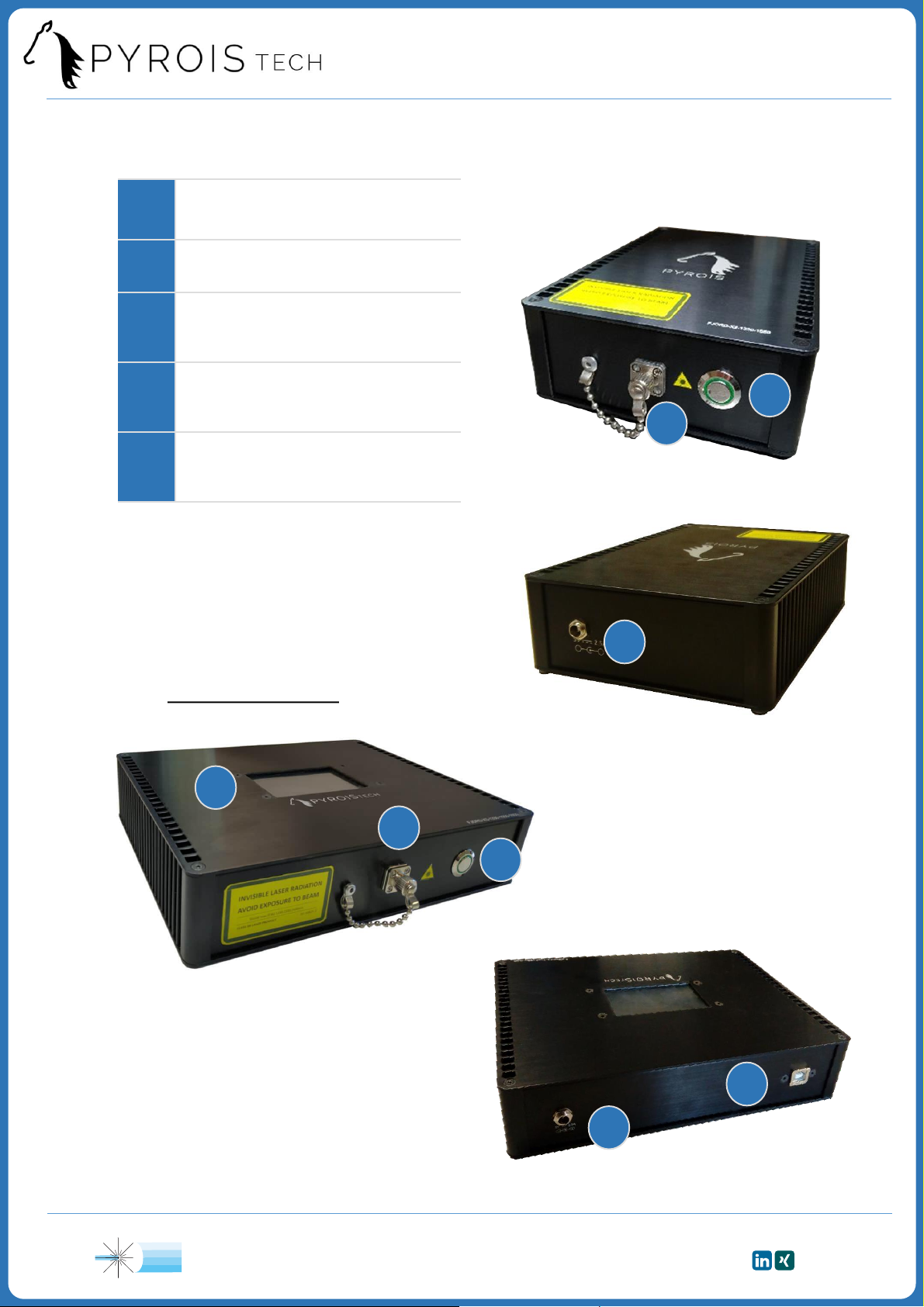
Pyroistech FJORD Series User manual

All rights reserved. No part of this publication may be reproduced, stored in a retrieval
system, or transmitted, by any means, electronic, mechanical, photocopying, recording, or
otherwise, without written permission from Pyroistech S.L.
This manual accompanies a product order and is subjected to the condition that it shall
not, by way of trade or otherwise, be lent, re-sold, hired out or otherwise circulated
without the prior consent of Pyroistech S.L. in any form of binding or cover other than
that in which it is published.
The specifications indicated in this manual are subject to change without prior notice.
Disclaimer
Every effort has been made to make this manual as complete and as accurate as possible,
but no warranty is implied on it. The information provided is on an “as is” basis. Pyroistech
S.L. shall have neither liability nor responsibility to any person or entity with respect to any
loss or damages arising from the information contained in this manual.
2
SI Scientific Instruments GmbH
SI

3
Table of Contents
0. Introduction………………………………………………....
1. Technical Specifications…………………………………..
2. Operation……………………………………………………..
2.1 Package Content……………………………………………………….....
2.2 Basic Operation…………………………………………………………....
2.3 Maintenance………………………………………………………………...
2.4 FJORD-series Diagrams………………………………………………..
2.5 Touch screen (available extra)……………….……………………...
2.5.1 Initial screen………………………………………………………………….....
2.5.2 SLED screen…………………………………………………………...............
2.5.3 Error management………………………………………………...............
2.6 USB connection (available extra)………………..………….........
2.6.1 App: Connection…….……………………………………………..............
2.6.2 App: Control and monitoring………………………………..............
2.6.3 Commands through USB connection…………………………….
3. Important Notes…………………………………….........
4. Warranty……………………………………………………..
5. Compliance………………………………………………….
5
5
7
7
7
7
8
9
9
10
11
12
12
13
14
15
17
17
SI Scientific Instruments GmbH
SI

0. Introduction
Thank you for purchasing this FJORD light source from Pyroistech.SL. This document
describes the FJORD light source and provides you with instructions for its correct
have any questions or doubts about this manual.
FJORD is the superluminescent diode (SLED) broadband light source that allows you to
combine up to 8 high power SLED, with peak wavelengths that range from 830 nm to
1650 nm. Its compact, silent and sturdy design permits its integration in whatever type of
application, covering a wide range of possibilities, from optical laboratories, fiber optics
testing, Bragg grating interrogation, tomography, or industrial sensors among others.
The FJORD light source can include one or both of the following two extras: a touch
screen to adjust the power of each SLED individually from 0 to 100% and a USB
connection that enables to do the same through the computer, allowing the remote
control of the source.
5
1. Technical Specifications
General characteristics
•Configurable spectral bandwidth with up to 8
SLEDs (see all the available SLED modules on
the next page)
•Max. optical power (fiber 8μm): -5dBm*
•Short stabilization time <1 min
•Temperature controlled ±0.1ºC
•Configurable output connector FC-PC/FC-APC
•Dimensions 18 x5x12.7 cm*
•High quality materials for a durable product.
•Compact, light and silent
Available extras
•Individual control of the power
of each SLED
•Touch screen option
•USB connection option
*These values may vary with the number and
model of the chosen SLED modules. The
dimensions correspond to a 2 SLED source.
SI Scientific Instruments GmbH
SI

6
Optical characteristics
The available SLED for configuring your own FJORD source are the following:
The central wavelength of each SLED is included in its own name. For example,
SLED HP1130 has a central wavelength of 1130 nm.
The power measurements shown in the graph correspond to each individual
SLED. The assembly of several SLED modules implies some power losses. Final power
measurements will be provided for each FJORD SLED light source separately at the
time of assembly.
Right now, we have available the FJORD configuration tool, that allows you to
combine up to 8 SLED to preview your desired output spectrum. Contact us through
Electrical characteristics
•Input voltage (VIN): 5 V
•Input current (IIN): 4 A max
(typical value, it may vary depending
on the model)
•Connector type: DC female 2.1 mm
Other characteristics
•Working Temperature: 15 -25ºC
•Relative Humidity: 20 -80% HR
SI Scientific Instruments GmbH
SI

2. Operation
2.1 Package Content
•Requested FJORD light source
•Power source
•Power cord
•User’s manual
Inspect carefully the devices and make sure there is no damage. On the contrary, do
repair or replacement information.
2.2 Basic operation
Insert the plug of the power cord into the power supply and connect the power
cord to the power outlet. Then, introduce the plug of the power supply into the light
source power input (DC female type).
Unscrew the cap of the FC-PC/FC-APC connector on the front face of the light
source and connect the fiber cable. Always do this step before turning on the light
source. Now, the FJORD light source is ready to be used.
Press the ON/OFF button to turn on the light source. The button will be lit up in
green while the source is working. Press again the button to turn off the light source.
USB connection
If your FJORD source has a USB connection (available extra) and you want to use
it, physically connect the source to the computer through the USB cable. If your
FJORD source has a touch screen (available extra), the message “USB Connected”
will appear on it once you have done the connection.
In order to end the USB connection, just disconnect the USB cable. If you are
using the app for the USB connection, it is recommended to click on “Disconnect”
in the first place (more information on section 2.6.2).
2.3 Maintenance
The output connector of the light source should be periodically cleaned employing
compressed air to remove the dust. It is recommended to have the output connector
with the cap on it whenever the light source is not being used. The connector of the
fiber used with the light source also has to be clean to ensure the best possible
performance.
7
SI Scientific Instruments GmbH
SI

2.4 FJORD-series diagrams
1Switch
(ON-OFF)
2Power input
3FC-PC/FC-APC
output connector
4Touch screen
(available extra)
5USB connector
(available extra)
2
1
3
4
5
3
1
Model with extras
Front view
Front view
Rear view
*The size of the source may vary with the
number of the SLED modules.
The standard FJORD on this page
corresponds to a FJORD-X2-1330-1550
model.
The FJORD with extras on this page
corresponds to a FJORD-X3-1330-1550-
1650 model.
Rear view
2
8
SI Scientific Instruments GmbH
SI

9
General ON/OFF button (1)
•If all the SLEDs are OFF, the general ON/OFF button will be OFF (grey). By
pressing it, the general button changes to the ON state (light green) and all the
SLEDs will be turned ON with the 100%of its power.
•If one or more SLEDs are ON, whatever the output power, the general ON/OFF
button will be ON (light green). By pressing it, the general button changes to
the OFF state (grey) and all the SLEDs will be turned OFF.
SLEDs section
Each SLED contained in the FJORD light source possesses a small rectangle (2)
in the initial screen with its name (3), the percentage of the nominal output power
(4) and a status circle (5)on the upper right corner of the rectangle. To access to
more detailed information about the SLED (see Figure 2 on the next page), please
touch the rectangle.
The status circle can have the following colours:
•Green: the SLED is operating correctly and its temperature has achieved the
value set as reference. See the first SLED on the left on Figure 1.
•Yellow: the SLED temperature hasn’t achieved yet the value set as reference.
Observe the second SLED starting from the left on Figure 1.
•Red:an error has occurred. In this case, a warning symbol (6) will appear in the
rectangle of the corresponding SLED. The warning won’t disappear until the
error has been solved (green or yellow circle) and we have accessed to the
screen of the corresponding SLED. See the third SLED starting from the left on
Figure 1.
These colours will be lighter if the SLED is ON and darker if the SLED is OFF.
1
2
3
4
1General ON/OFF button
2SLED rectangle
3
SLED name
4
% of nominal P
OUT
5
Status circle
6
Warning
Figure 1. Initial screen
2.5 Touch screen (available extra)
2.5.1 Initial screen
5
6
SI Scientific Instruments GmbH
SI

10
1SLED information
2SLED ON/OFF button
3
% of nominal P
OUT
4
Arrows
5
Slide bar
6
Spectrum
view button
7
Return
arrow
Figure 2. SLED screen
1
3
4
2
5
6
7
SLED information (1)
On the left of the screen, the following information can be read:
•Name of the SLED
•Central wavelength of the SLED
•Full width at half maximum (FWHM)
Control of the output power
On the right of the screen, the percentage of the nominal output power of the SLED
can be adjusted from 0% to 100% with the following controls:
•SLED ON/OFF button (2):
–This button is OFF (grey) if the percentage is equal to 0%. By pressing it, it will
change to the ON state (light green) and the output power will be set to 100%.
–This button is ON (light green) if the percentage is higher than 0%. By pressing it, it
will change to the OFF state (grey) and the output power will be set to 0%.
•SLED Temperature (ºC)
•SLED Current (mA)
•Type of error (only when an error has
occurred, see Figure 5 on next page)
•Keypad (3): by clicking on the number, a keypad will
appear (Figure 3). A percentage 0%-100% can be
introduced by using it. You can erase a digit by pressing
‘DEL’. Press ‘OK’ to confirm the percentage. If the value
introduced is higher than 100%, it will be replaced by
the previous valid percentage.
•Arrows (4): using the up/down arrows will increase/decrease the current percentage
of the nominal output power by 1%.
•Slide bar (5): it permits you to adjust the output power from 0% to 100%. While
dragging the slide bar, it will be in yellow, and it will change to green once a value has
been selected.
On the bottom of the screen, if we click on “Spectrum view” (6), we will see the spectral
power distribution of the corresponding SLED (see Figure 4 on next page). The arrow (7)
enables to return to the initial screen.
Figure 3. Keypad
2.5.2 SLED screen
The sequence ‘70925841’written on the keypad will restore
all the source parameters to their Factory Mode values
SI Scientific Instruments GmbH
SI

11
Figure 4. Spectrum view screen
When an error takes place, the user is automatically returned to the initial screen.
The SLED where the error has occurred can be quickly identified by looking to the
status circle of each SLED and observing which one is red. There will also be a
warning symbol in the rectangle of the SLED (see again the third SLED starting from
the left on Figure 1 on page 9).
The SLED with the error is turned off and remains like this 10 s. Then it is turned
on in the same conditions (power %) in which it was operating before the error
happened. If the error persists, the SLED will be turned off again during 10 s. This
cycle will be repeated until the error is solved.
The warning won’t disappear until the error has been solved (circle green or
yellow) and we have accessed to the screen of the corresponding SLED (see Figure 5,
in this case, error 1 took place). This way we will be able to know which type of error
happened. The error codes are given in Table 1:
Code Type of error
1 T higher than maximum T
2 T lower than minimum T
3 Error in the driver of the SLED
4T unexpectedly deviates from
reference value after stabilizing
5
Error in the second driver of
the SLED (only some SLEDs
have a second driver)
Table 1. Possible errors of the SLED
The y axis is the output
power of the SLED in
arbitrary units in logarithmic
scale, where 1 corresponds to
the maximum. The x axis is
the wavelength in nm.
By pressing the arrow on
the bottom left corner, you
will be returned to the SLED
screen (see Figure 2 on p.10).
2.5.3 Error management
Figure 5. SLED screen when an error occurs
SI Scientific Instruments GmbH
SI

12
2.6 USB connection (available extra)
The aim of the USB connection is to allow the user to control the output power of
each SLED and monitor its temperature through the computer. This option permits to
remotely command the source through a VPN connection, for instance; avoiding the
inconvenience of physically going to the laboratory to check or adjust the equipment.
An app is provided (contact us through [email protected] for more
information) and commands can also be directly sent to the source to check and
modify additional variables. Both are explained in detail in the following pages.
2.6.1 App: Connection
Initially, only the buttons “Port” and “Connect” are available. In order to effectively
connect the FJORD light source to the computer, these steps must be followed:
•Click on the button “Port” (1)to update the list of ports used by the devices
connected to the computer.
•Select on the drop-down menu (2)to the right of the button “Port” the port that
corresponds to the FJORD light source.
•Choose the baud rate (3), on the right of the button “Connect”.By default, the
baud rate is 115200.
•Click on the button “Connect” (4).
12
1
3
4
Figure 6. Main window of the FJORD app. Connection
2
SI Scientific Instruments GmbH
SI

13
2.6.2 App: Control and monitoring
Once the connection has been made, the drop-down menu that allows you to
choose the desired SLED and the widgets that let you control the output power
will be active. The connection between the computer and the FJORD light source
can be closed at any time by clicking on “Disconnect” (5).
•In the drop-down menu (6)we can select each SLED that is in the light source.
•For the selected SLED, the temperature in ºC is shown (7). This value is
updated every second.
•The output power of the selected SLED can be varied from 0 to 100 %by
using the slide bar (8)or by directly introducing the desired value in the
regulator (9). The arrows permit to increase/decrease this value by 1% (10).
•After each change, the button “SET POWER” (11) has to be pressed to update
the new value of the output power of the corresponding SLED in the FJORD
light source.
Figure 7. Main window of the FJORD app. Control and monitoring
6
6
5
78
910
11
SI Scientific Instruments GmbH
SI

14
2.6.3 Commands through USB connection
The sequence that has to be sent in order to read or write the value of a
variable must have the following structure:
1. #SLED (1 byte): number of the SLED whose parameters we want to read or
write. The first SLED contained in the source is assigned number 1 and so on.
2. ADDRESS (1 byte): the address of the variable we want to read or write. The
addresses of the different parameters are given in Table 2.
3. FLOAT 32bits: in case of a writing command, the new value for the variable
we want to modify has to be introduced here with this format. In case of a
reading command, nothing has to be sent.
4. SPACE /n: end of the message, where a space “ “ has to be included. In case
of a reading command, directly introduce the space after the address.
Comments
•It is not recommended to overwrite the values of the variables that are
shadowed (minimum and maximum allowable T, KP and KI).
•Reference T is the target temperature for the temperature control. The default
value is 20 ºC and it is not recommended to introduce a lower one.
•Addresses 0x20 and 0x24 are not used.
•Modifying the maximum and minimum allowable currents through the TEC will
affect the velocity of the temperature control.
•Instantaneous T of the SLED is the real temperature of the SLED while
measured T of the SLED is its value after applying a filter. Both values can only
be read, not written.
Sending 0xFFFFFFFFFFFF (6 bytes) followed by /n will restore all the
source parameters to their Factory Mode values
Not following the recommendations on this page can result in
undesired behaviour that can cause damage to the light source,
which is NOT covered by Pyroistech’s warranty
Variable
Address
Reference T (ºC) 0
Minimum allowable T (ºC) 4
Maximum allowable T (ºC) 8
Proportional gain KP 12
Integral gain KI 16
Variable
Address
Maximum I through TEC (A) 28
Minimum I through TEC (A) 32
Reference I through the SLED (mA) 36
Instantaneous T of the SLED 40
Measured T of the SLED 44
Table 2. Variables and their corresponding addresses
SI Scientific Instruments GmbH
SI

3. Important Notes
Before operation
•Please read the rest of this manual carefully if this is your first time using this equipment.
•Do not remove or alter any labels or safety features on this equipment or open the
equipment. Doing so will void your warranty and create an unsafe operating
environment.
•There are no parts inside the equipment that the user must manipulate. There are
dangerous currents inside the equipment. You should only allow the technical staff of
Pyroistech S.L. to repair or work with this equipment. SLEDs are very sensitive to
electrostatic discharge and working with them without the appropriate measures can
damage them.
•Inspect this unit and its power before using it for the first time. Do not use this device if
it is damaged in any way. Contact us to inquire about repair or replacement possibilities.
During operation
There are 2 aspects that affect the operation and performance of a SLED source in a very
relevant way: optical feedback and temperature.
Optical feedback
Optical feedback occurs when part of the optical power is reflected by one of the
elements of the experimental setup and returns to the SLED cavity. This phenomenon
occurs in any type of assembly, but in the case of SLEDs it is especially critical, because its
internal operation is based on NO optical feedback (or at least very reduced compared to
that which occurs in a laser).
•The warranty does not cover problems associated with optical feedback, simply
because it is a problem that may be caused by an experimental end-user assembly, and
it is not possible to test and ensure that optical feedback will not cause problems for all
types of assembly.
•As a safety threshold, it is recommended to ensure that the optical feedback at each
wavelength is at least 40 dB lower than the direct power emitted by the source at that
wavelength. Higher values do not necessarily have to be dangerous, but they do
increase the risk of critical failure. REALIZE that the threshold is a reference value that
does not imply any guarantee.
•The following phenomena may be indicative of optical feedback: sudden drops in
power, alterations in the shape of the spectrum or the appearance of narrow peaks in
the emission spectrum. In extreme cases, a serious optical feedback problem, even if
momentary, can lead to an SLED breaking immediately.
•The presence of an optical feedback problem may be due to a specific error or to the
continued incorrect use of the equipment, which may appear immediately or take time
to manifest. Therefore, it is very difficult to identify the real cause of the problem once
it manifests itself.
15
SI Scientific Instruments GmbH
SI

16
•Improper mounting connections can lead to optical feedback problems. Therefore, it is
advisable to pay attention to them. Additionally, it is recommended to use FC/APC
connectors instead of FC/PC because the reflection losses of the first type of connectors
are lower.
•The mentioned problems may have other causes that are easy to solve. For example, an
unexpected sudden drop in power of afew dB over the entire spectrum of the source
may be due to the accumulation of dust on a connector. But it is recommended not to
ignore these details because they can be an indicator of an optical feedback problem,
much more serious for the source and with potentially serious consequences.
Temperature
Temperature is always an important factor in light sources. The worse the temperature
regulation of a source, the longer its stabilization time will be. But temperature control is
especially critical in the case of a SLED, considered more sensitive to temperature than
other technologies (LED, laser).
Every FJORD source has a temperature control of each SLED with ±0.1ºC precision. This
temperature control is implemented with several security mechanisms. This does not
mean that the recommendations indicated in this manual should not be followed.
•It is recommended to ensure that the ambient temperature is in the 15-25ºC range, to
avoid direct exposure to sunlight and to check that the equipment is not immediately
adjacent to others that impede natural convection cooling to achieve optimal operation.
•Failure to follow the above recommendations may not affect the output power of the
source, slightly affect it, but in some cases, it will shorten the life of the SLEDs,
depending on how good or bad the cooling is.In any case, the correct operation of the
source and the consequences derived from it in case of not following the above
recommendations are not guaranteed.
Eye Safety
•Optical radiation can damage your eyes. DO NOT look directly at the source output.
•FJORD sources emit infrared light, not visible to the human eye, which can be dangerous
depending on the mounting configuration (including, but not limited to, optics, current,
and temperature). Follow the safety recommendations given in IEC 62471 when working
with these light sources.
CAUTION !
Do NOT stare directly
at the light beam
SI Scientific Instruments GmbH
SI

17
4. Warranty
Pyroistech’s general warranty for a product has a 1 year duration.
This warranty includes repairs and replacement of damaged parts due to a malfunction
of the source, as long as said malfunction can be attributed to errors made in the
manufacture of it by Pyroistech SL, not to a punctual misuse of the source or to a
continued incorrect employment of it by the user, whether conscious or unconscious,
due to not having followed the operation recommendations indicated by Pyroistech SL
There is the possibility of extending this guarantee. For more information, contact
Pyroistech S.L.
Electromagnetic compatibility
•Portable RF communications equipment (including peripherals such as antenna cables
and external antennas) should be used no closer than 30 cm (12 inches) to any part of
this equipment. Otherwise, degradation of the performance of this equipment could
result.
•The use of cables, power supplies, transformers and accessories other than those
specified by Pyroistech S.L., in addition to not being covered by the warranty, may lead
to increased emissions and/or decreased electromagnetic compatibility.
WEEE
Compliance
5. Compliance
This device complies the following standards:
Contact Pyroistech S.L. if you
require more information about
the electromagnetic compatibility
of the product.
If you consider that the product has reached the end of its
useful life and you want to dispose of it, you can contact
Pyroistech S.L. so that it is in charge of its management.
EMC 2014/30/EU
RoHS-compliant
Federal
Communications
Commision
SI Scientific Instruments GmbH
SI
Table of contents
Other Pyroistech Lighting Equipment manuals