12 13
INSTALLATION AND OPERATION MANUAL SOLAR MODULES Q.PEAK DUO BLK-G6+ / AC – Q CELLS INSTALLATION AND OPERATION MANUAL SOLAR MODULES Q.PEAK DUO BLK-G6+ / AC – Q CELLS
2 PLANNING
2.4 MICROINVERTER PLANNING
Installation Site
The microinverter housing is designed for outdoor installation and
complies with the NEMA 250, type 6 environmental enclosure
rating standard:
NOTE!
NEMA 6 Rating Definition:
Indoor or outdoor use primarily to provide a degree of protection
against hose-directed water, the entry of water during occasional
temporary submersion at a limited depth, and damage from external
ice formation
The Enphase Q Cable is available with connector spacing options
to accommodate installation of PV modules in portrait or landscape
orientation. For Enphase Q Cable ordering information, see “Enphase
Q Cable Planning and Ordering” on page 30.
Planning the Racking
Plan the racking position with the microinverter in mind. Ensure that the
racking does not interfere with the microinverter and its connectors.
Grounding Considerations
The Enphase Microinverter models listed in this guide do not require
grounding electrode conductors (GEC), equipment grounding con-
ductors (EGC), or grounded conductors (neutral). Your Authority
Having Jurisdiction (AHJ) may require you to bond the mounting
bracket to the racking. If so, use UL2703 hardware or star washers.
The microinverter itself has a Class II double-insulated rating, which
includes ground fault protection (GFP).
Branch Circuit Capacity
Plan your AC branch circuits to meet the following limits for maximum
number of microinverters per branch when protected with a 20 amp
(maximum) over current protection device (OCPD).
MAXIMUM* IQ 7+ MICROS
PER AC BRANCH CIRCUIT (240 VAC)
13
MAXIMUM* IQ 7+ MICROS
PER AC BRANCH CIRCUIT (208 VAC)
11
NOTE!
*Limits may vary. Refer to local requirements to define the number
of microinverters per branch in your area.
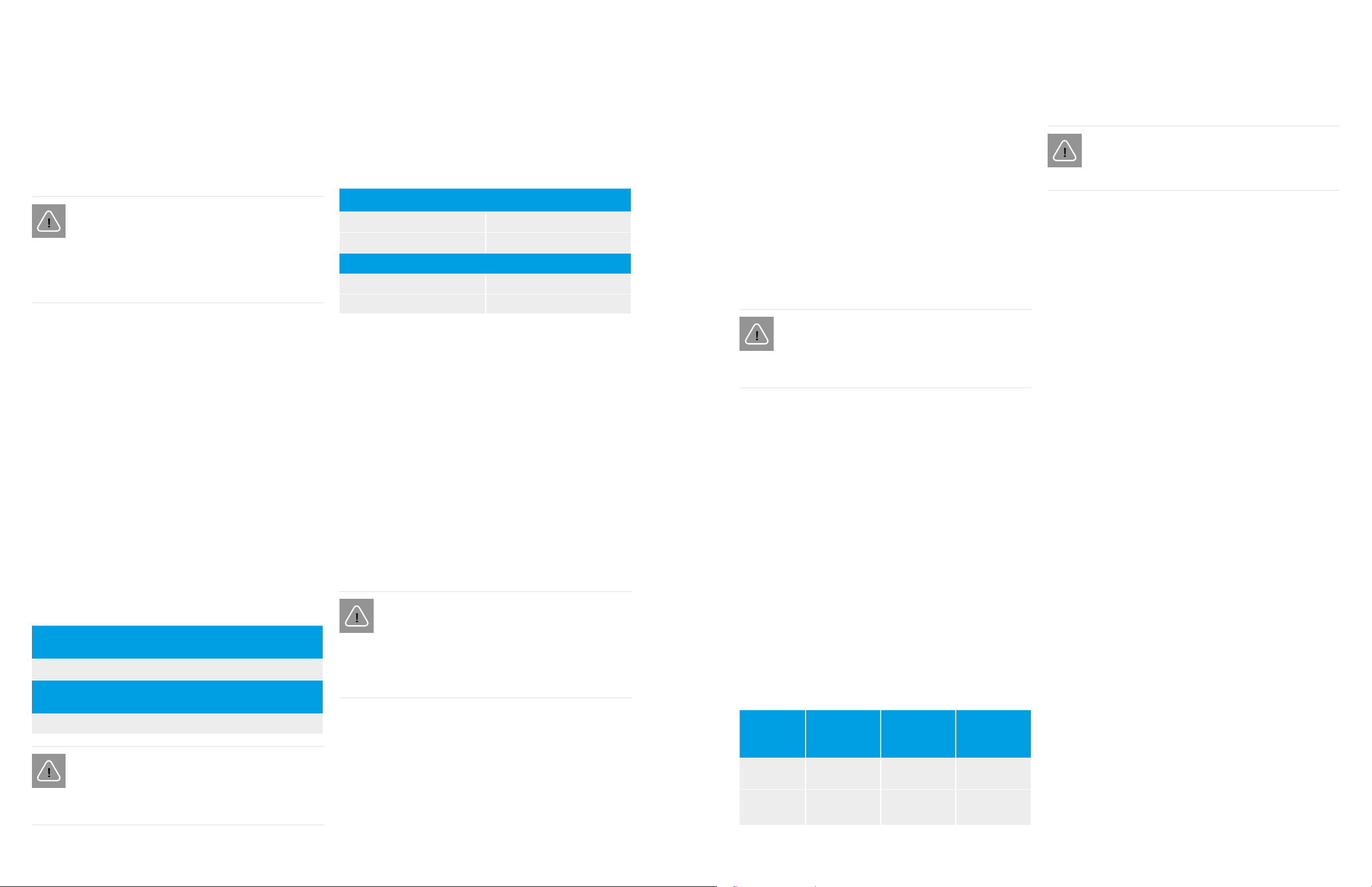
Utility Service Requirements
The Enphase IQ Microinverter for ACM work with a single-phase
service. Measure AC line voltages at the electrical utility connection
to confirm that it is within the ranges shown:
240 VOLT AC, SINGLE PHASE
L1 to L2 211 to 264 VAC
L1, L2 to ground 106 to 132 VAC
208 VOLT AC, SINGLE PHASE
L1 to L2 183 to 229 VAC
L1, L2 to ground 106 to 132 VAC
Wire Lengths and Voltage Rise
When planning the system, you must select the appropriate AC
conductor size to minimize voltage rise. Select the correct wire size
based on the distance from the beginning of the AC branch circuit
to the breaker in the load center. Enphase recommends a voltage
rise total of less than 2% for the sections from the AC branch circuit
to the breaker in the load center.
Enphase provides guidance about choosing wire size and maximum
conductor lengths in the Voltage Rise Technical Brief at enphase.com
/support. Refer to this brief for voltage rise values in Enphase Q
Cables and on how to calculate voltage rise in other wire sections
of the system.
Standard guidelines for voltage rise on feeder and AC branch circuit
conductors might not be sufficient for microinverter AC branch
circuits that contain the maximum allowable microinverters. This is
due to high inherent voltage rise on the AC branch circuit.
NOTE!
Best practice:
Center-feed the branch circuit to minimize voltage rise in a fully-pop-
ulated branch. This practice greatly reduces the voltage rise as
compared with an end-fed branch. To center-feed a branch, divide
the circuit into two sub-branch circuits protected by a single OCPD.
2 PLANNING
2.4 FOR MICROINVERTER PLANNING
Lightning and Surge Suppression
Enphase Microinverters have integral surge protection greater
than most traditional inverters. However, if the surge has sufficient
energy, the protection built into the microinverter can be exceeded,
and the equipment can be damaged. For this reason, Enphase
recommends that you protect your system with a lightning and/or
surge suppression device. In addition to having some level of surge
suppression, it is also important to have insurance that protects
against lightning and electrical surges. Enphase has tested the
following devices:
• Leviton 51110-SRG
• Schneider SquareD HEPD50
NOTE!
Protection against lightning and resulting voltage surge must be in
accordance with local standards.
Parts and Tools Required
In addition to the AC Modules, you will need the following:
Enphase Equipment
•
Enphase IQ Envoy (model ENV-IQ-AM1-240) communications
gateway or IQ Combiner (model X-IQ-AM1-240-2 or 240-3):
required to monitor solar production. For installation information,
refer to the Enphase IQ Envoy Installation and Operations Manual.
•
Enphase Installer Toolkit: Download the Enphase Installer Tool-
kit mobile app and open it to log in to your Enlighten account.
With this app, you can scan microinverter serial numbers and
connect to the IQ Envoy to track system installation progress.
To download, go to enphase.com/toolkit.
• Tie Wraps or Cable Clips (Q-CLIP-100)
• Enphase Sealing Caps (Q-SEAL-10) for any unused drops on
the Enphase Q Cable
• Enphase Terminator (Q-TERM-10) typically two needed per
branch circuit
• Enphase Disconnect Tool (Q-DISC-10)
• Field Wireable Connectors (male and female: Q-CONN-10M
and Q-CONN-10F) (optional)
• Enphase Q Cable:
CABLE
MODEL
CONNECTOR
SPACING
PV MODULE
ORIENTATION
CONNECTOR
COUNT PER
BOX
Q-12-10-240 1.3m Portrait 240
Q-12-17-240 2.0m Landscape
(120-cell)
240
NOTE!
Only Enphase connectors / solar cables are permitted.
Other Items
• Racking, AC junction box, homerun
• Tools:
• screwdrivers
• wire cutter
• voltmeter
• torque wrench
• sockets and wrenches for mounting hardware
•
Crimp tool PV-CZM-18100, -019100, or -22100 for field wireable
connectors (optional)
• Compatible cable clips