9
IMPORTANT:
REGARDING THE INCLUDED MOUNTING SCREWS!
Before marking where to attach the gate, make sure
you have a solid surface for mounting the gate to. The
included screws are intended for the following locations.
Directly into wood
The Short 2” (50 mm) Screws are used when mounting
directly onto wood, for example in a door frame or other
framed opening. If installing into hardwood, first drill a
pilot hole. The shorter screw in the pack is used for the
top of the FastMount™ Locking Rail.
Into a stud behind drywall
Use stud-finder to locate where there is a stud behind the
drywall. Then use the Medium 2.75” (70 mm) Screws to
mount the gate into the stud. If attaching the gate using
Baseboard Spacers, see page 12, use the Long 3.25”
(85 cmm) Screws to secure into the stud. The shorter
screw included in both packs used for the top of the
FastMount™ Locking Rail.
Any other surface
If mounting into drywall, brick or other
surface, use only the appropriate
hardware for that surface. Consult with
a certified child proofer, a handyman
or your local hardware store if you are
unsure. Never mount into cavity wall or
hollow brick.
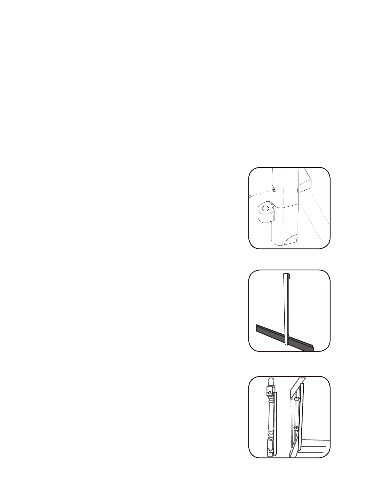
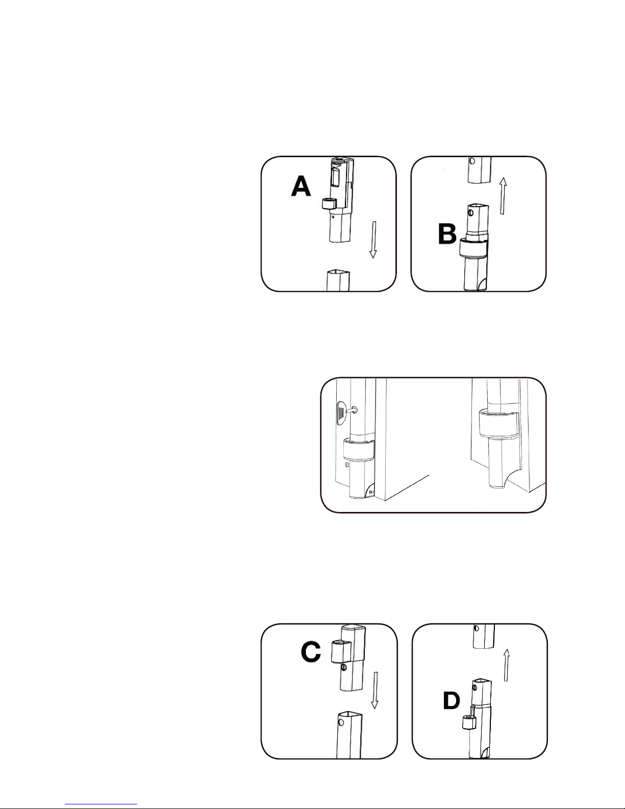
Step 3
With the FastMount™ Hinge Rail resting
on the floor in the desired location, use
the provided Installation Level to make
sure it is vertical. Use the Marking Tool
to mark the 2 screw locations.