QEP Brutus 60010 User manual

ATTENTION!
Lire et suivre toutes les directives
de sécurité et d’opération avant
d’utiliser cette scie.
CAUTION!
Read and follow all safety
and operating instructions
before using this saw.
¡AVISO!
Lea y siga todas las instrucciones de
funcionamiento y seguridad antes de
usar esta sierra.
18" Professional Tile Saw
OWNER’S MANUAL
Scie àCarreaux de 460mm
MANUEL D’UTILISATION
S i e rra Eléctrica Profesional de 460mm
MANUAL DE OPERACIÓN
STK# 60010
by
GARANTIE LIMITÉE
Faire référence à la carte de guarantie.
LIMITED WARRANTY
Refer to warranty card.
GARANTIA LIMITADA
Referirse a la tarjeta de guarantia.

TABLE DES MATIÈRES
Directives Générales de Sécurité .........................17
Installations Électriques..........................................18
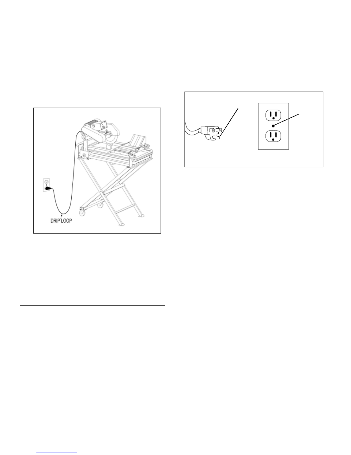
Cordons d’Alimentation ...........................................19
Guide de Fonctionnement .......................................19
Caractéristiques de la Scie ....................................20
Réglage et Fonctionnement....................................21
Mise en Garde ...........................................................21
Assemblage de l’Établi............................................22
Attacher l’Armature de l’Établi...............................22
Assemblage de la Tête de Coupe..........................23
Assemblage du Protège-Lame ...............................23
Installation de la Lame Diamantée ......................24
Installation du Plateau pour l’Eau .........................24
Installation de la Pompe à Eau ..............................24
Sécurité de la Pompe à Eau....................................25
Fonctionnement et Entretien de la Pompe à Eau
............25
Ajustage de la Vitesse de la Lame et
Remplacement de la Courroie................................25
Profondeur de la Coupe...........................................26
À Faire etàne pas Faire avec la Lame Diamantée
.........26
Fonctionnement de la Coupe..................................26
Coupes Droites avec le Guide de Fente ...............26
Coupesd’Angle à 45° avec le Guide d’Angles
...........27
Coupes d’Onglets avec la Boîte à Onglets ...........27
Entretien de la Scie..................................................27
"Dressage" de la Table de Coupe .........................27
Alignement de la Lame............................................28
Nettoyage .................................................................. 28
Dépannage .................................................................28
Liste des Pièces ........................................................29
Diagramme des Pièces Éclaté ...............................29
CONTENIDO
Instrucciones de Seguridad General....................30
Requisitos Eléctricos ...............................................31
Cables de Extensión.................................................32
Guía de Operación Específica................................32
Características de la Sierra....................................33
Configuración y Operación .....................................34
Advertencia................................................................34
Ensamblaje del Soporte...........................................35
Sujeción del Armazón al Soporte..........................35
Ensamblaje del Cabezal Cortador..........................36
Ensamblaje de la Protección de la Cuchilla .........36
Instalación de la Cuchilla de Diamante ..............37
Instalación de la Bandeja para Agua...................37
Instalación de la Bomba de Agua .........................37
Medidas de Seguridad para la Bomba de Agua...38
Operación y mantenimiento de la bomba de agua
..38
Ajuste de la Velocidad de la Cuchilla y
Reemplazo de la Banda...........................................38
Profundidad del Corte ..............................................39
Qué Hacer y qué no Hacer con la Cuchilla de Diamante .
39
Operación de Corte...................................................39
Cortes Rectos con Guía de Corte...........................39
Cortes en Ángulos de 45 Grados con Guía de Ángulo
.40
Cortes de Inglete con Bloque de Ingletes ...........40
Mantenimiento de la Sierra....................................40
Nivelación de la Tabla para Cortar .......................40
Pulido de la Cuchilla................................................41
Limpieza......................................................................41
Resolución de problemas........................................41
Lista de piezas...........................................................42
Diagrama desglosado de piezas............................42
TABLE OF CONTENTS
General Safety Instructions......................................4
Electrical Requirements............................................5
Extension Cords...........................................................6
Specific Operation Guide..........................................6
Saw Features...............................................................6
Set Up and Operation.................................................8
Warning ........................................................................8
Stand Assembly...........................................................9
Attaching Frame to Stand..........................................9
Cutting Head Assembly............................................10
Blade Guard Assembly ............................................10
Diamond Blade Installation ...................................11
Water Tray Installation ............................................11
Water Pump Installation..........................................11
Water Pump Safety...................................................12
Water Pump Operation & Maintenance...............12
Blade Speed Adjust. & Belt Replacement...........12
Cutting Depth .............................................................13
Diamond Blade Do’s & Don’ts.................................13
Cutting Operation......................................................13
Straight Cuts with Rip Guide ..................................13
45oAngle Cuts with Angle Guide..........................14
Miter Cuts with Miter Block...................................14
Saw Maintenance.....................................................14
“Truing” the Cutting Table.......................................14
Blade Dressing..........................................................15
Cleaning......................................................................15
Trouble Shooting .......................................................15
Parts List.....................................................................16
Exploded Parts Diagram..........................................16
18" Professional Tile Saw
Scie àCarreaux de 460mm
S i e rra Eléctrica Profesional de 460mm
STK# 60010
by
MOTOR: 2HP 120V-60Hz 15 AMPS
RPM: 3,450 & 2,450 (dual speed)
BLADE: 10"
ARBOR: 5/8"
CUTS TILE: 18" Rip, 13" Diagonal
MAX TILE RIP THICKNESS: 1-1⁄2"
MAX TILE MITER THICKNESS: 3/4"
SAW DIMENSIONS: 40"L x 22"W x 47"H
NET WEIGHT: 116 lbs. (w/stand)
SPECIFICATIONS SPÉCIFICATIONS ESPESIFICACIONES
MOTEUR: 2HP 120V-60Hz 15 AMPS
T/M: 3,450 et 2,450 (double vitesse)
LAME: 25,4 cm (10 po)
TONNELLE: 1,6 cm (5/8 po)
DÉCOUPES DU CARREAU: Fente de 45,7 cm
(18 po), diagonal de 33 cm (13 po)
ÉPAISSEUR MAX. DU CARREAU: 3.8 cm (1 1 /2 po)
ÉPAISSEUR MAX. DE L’ONGLET: 1.9 cm (3/4 po)
DIMENSIONS DE LA SCIE: 101,6 cm (long)
x 55,9 cm (large) x 119,4 cm (haut) (40 po x 22
po x 47 po)
POIDS NET: 52,6 kg (116 lb) (avec l’établi)
MOTOR: 2HP 120V-60Hz 15 AMPS
T/M: 3,450 y 2,450 (velocidad dual)
CUCHILLA: 25.4 cm (10 pulg.)
EJE: 1,6 cm (5/8 pulg.)
CORTA LOSETAS: 45.7 cm (18 pulg.) en corte,
33 cm (13 pulg.) en diagonal
GROSOR MAX. PARA CORTE DE LOSETAS:
3.8 cm (1-1⁄2 pulg.)
GROSOR MAX. PARA CORTE DE INGLETES:
(1.9 cm (3/4 pulg.)
DIMENSIONES DE LA SIERRA: 101,6 cm (L)
x 55,9 cm (AN) x 119,4 cm (AL) (40 pulg. x 22
pulg. x 47 pulg.)
PESO NETO: 52,6 kg (116 lb) (c/soporte)

- 4 -
GENERAL SAFETY INSTRUCTIONS
Read this owner's manual completely and make sure you
understand all of it's safety guidelines.
1. KEEP GUARDS IN PLACE and in working order.
2. REMOVE ADJUSTING KEYS & WRENCHES.Before
turning on the tile saw, make sure the keys and
adjusting wrenches have been removed.
3. KEEP WORK AREA CLEAN.Cluttered areas and
benches invite accidents.
4. ALWAYS REMAIN ALERT WHEN THE SAW IS IN
USE.Inattention on the part of the operator may lead
to serious injury.
5. DON’T USE IN A DANGEROUS ENVIRONMENT.
Don’t use power tools in damp or wet locations or
expose them to rain. Keep work area well lit.
6. KEEP CHILDREN AWAY.All visitors should remain
at a safe distance from work area.
7. MAKE WORKSHOP CHILD-PROOF.Unplug power
tools and secure dangerous tools when not in use. Lock
tool cabinets and workshop doors when unattended.
8. USE THE RIGHT TOOL. Don’t force a tool or
attachment to do a job for which it was not designed.
It has been designed to operate at maximum safety
and performance levels.
9. USE THE PROPER EXTENSION CORD.Make sure
your extension cord is in good condition. When using
an extension cord, be sure to use one heavy enough to
carry the current your product will draw. An undersized
cord will cause a drop in line voltage resulting in loss
of power and overheating. Table (see Table 1) shows
the correct size to use depending on cord length and
nameplate ampere rating. If in doubt, use the next
heavier gauge. The smaller the gauge number, the
heavier the cord.
10. DO NOT FORCE THE MATERIAL BEING CUT.
Always let the blade cut at its own speed.
11. WEAR PROPER APPAREL.Do not wear loose
clothing, neckties, rings, bracelets or other jewelry
which may get caught in moving parts. Non-slip foot
wear is recommended. Wear protective hair covering
if you have long hair.
12. ALWAYS USE SAFETY GLASSES.Also use face or
dust mask for commercial cutting operations. Everyday
eyeglasses only have impact-resistant lenses, they are
NOT safety glasses.
13. SECURE WORK.Use clamps or a vise instead of your
hand to hold work when practical. This safety
precaution allows for proper tool operation using both
hands.
14. DON’T OVERREACH.Keep proper footing and
balance at all times.
15. MAINTAIN TOOLS WITH CARE.Keep tools clean
and in good working condition for maximum safety
performance. Follow instructions for lubricating and
changing accessories.
16. DISCONNECT TOOLS BEFORE SERVICING – when
changing accessories, such as blades, bits, cutters, etc.
17. REDUCE THE RISK OF UNINTENTIONAL
STARTING.Make sure switch is in OFF position before
plugging in.
18. USE RECOMMENDED ACCESSORIES.Consult the
owner’s manual for recommended accessories. The use
of improper accessories may increase risk of injury.
19. DO NOT DRY CUT WITH BLADES DESIGNED FOR
WET CUTS.
20. MAKE SURE YOU USE THE CORRECT BLADE for
the material you are cutting. Example: porcelain tile
requires a special blade designed especially for
porcelain.
21. NEVER STAND ON TOOL.Serious injury could occur
if the wet saw is tipped or if the cutting tool is
unintentionally contacted.
22. CHECK DAMAGED PARTS.Before further use of the
tool, damaged part(s), (i.e., guard) should be carefully
checked to determine that it will operate properly and
perform its intended function. Check for alignment of
moving parts, binding of moving parts, breakage of
parts, mounting and any other condition that may affect
the saw’s operation. A guard or other part that is
damaged should be properly repaired or replaced.
23. ENSURE THAT THERE IS A CONTINUOUS FLOW
OF WATER to both sides of blade during operation.
24. CHECK DIAMOND BLADES CAREFULLY FOR
CRACKS, NICKS, MISSING DIAMOND MATRIX OR
OUT-OF-ALIGNMENT CONDITION.Replace damaged
blades immediately.DO NOT USE DAMAGED BLADES.
They may cause bodily injury.
25. DIRECTION OF FEED.Feed work into the blade
against the direction of rotation of the blade only.
26. DO NOT ALTER THE PLUG OR USE A 2-PRONG
RECEPTACLE.This saw is equipped with a 3-prong
electrical plug.
27. NEVER LEAVE TOOL RUNNING UNATTENDED.
Turn power off. Don’t leave tool until it comes to a
complete stop.

- 5 -
29. POSITIONING OF TILE SAW
A. To avoid the possibility of the appliance plug
or receptacle getting wet, position the tile saw to one
side of a wall-mounted receptacle to prevent water from
dripping onto the receptacle or plug. The user should
arrange a “drip loop” in the cord connecting the saw
to a receptacle (see Fig 1). The “drip loop” is that part
of the cord below the level of the receptacle, or
connector if an extension cord is used, to prevent water
traveling along the cord and coming in contact with the
receptacle.
B. If the plug or receptacle does get wet, DO NOT
unplug the cord. Disconnect the fuse or circuit
breaker that supplies power to the tool. Then,
unplug and examine for presence of water in
the receptacle.
(B) GROUNDED
OUTLET BOX
METAL
SCREW
(A) GROUNDING PIN
•DO NOT MODIFY THE PLUG if it will not fit the
outlet. Have the proper outlet installed by a qualified
electrician.
•IMPROPER CONNECTION OF THE EQUIPMENT-
GROUNDING CONDUCTOR CAN RESULT IN A
RISK OF ELECTRIC SHOCK.The conductor with
insulation that is green on the outside (with or without
yellow stripes) is the equipment-grounding conductor.
If repair or replacement of the electrical cord or plug
is necessary, do not connect the equipment-grounding
conductor to a live terminal.
•CHECK WITH A QUALIFIED ELECTRICIAN or
service personnel if the grounding instructions are
not completely understood, or if in doubt as to whether
the tool is properly grounded.
•USE ONLY 3-WIRE EXTENSION CORDS that have
3-prong grounding plugs and 3-pole receptacles that
accept the tile saw’s plug.
•REPAIR OR REPLACE DAMAGED OR WORN
CORD IMMEDIATELY.
•IF THE PLUG OR RECEPTACLE DOES GET WET,
DO NOT UNPLUG THE CORD.Disconnect the fuse
or circuit breaker that supplies power to the tool. Then,
unplug and examine for presence of water in the
receptacle.
•ONLY UL-LISTED EXTENSION CORDS SHOULD
BE USED WITH THIS PRODUCT.
•DO NOT LET YOUR FINGERS TOUCH THE
TERMINALS of plug when installing or removing
the plug to or from the outlet.
Fig 1
Fig 2
ELECTRICAL REQUIREMENTS
•THIS TILE SAW MUST BE CONNECTED TO A
GROUNDED POWER SOURCE while in use to protect
the operator from electrical shock (see Fig 2).
•IN THE EVENT OF A MALFUNCTION OR
BREAKDOWN,grounding provides a path of least
resistance for electrical current to reduce the risk of
electrical shock. The tile saw is equipped with an
electrical cord with a grounding conductor and a
grounding plug. Insert the 3-prong electrical plug into
a 3-pole receptacle that is properly installed and
grounded in accordance with all local codes and
ordinances.
GENERAL SAFETY (Cont.)
NOTE: This tool is intended for use on a circuit that has an
outlet that looks like the one illustrated in Fig 2(B). The tool
has a grounding plug that looks like the plug illustrated in
Fig 2 (A). The green-colored rigid prongs extending from
the adapter must be connected to a permanent ground such
as a properly grounded outlet box.

- 6 -
TABLE 1
Volts
120V 25ft. 50ft. 100ft. 150ft.
240V 50ft. 100ft. 200ft. 300ft.
18 16 16 14
18 16 14 12
16 16 14 12
14 12 Not
Recommended
Total length of cord
More Not More
Than Than
0 6
6 10
10 12
12 16
AWG
Ampere Rating
•IMPROPER USE OF EXTENSION CORDS MAY
CAUSE INEFFICIENT OPERATION OF YOUR TOOL,
which can result in overheating. Be sure your extension
cord is rated to allow sufficient current flow to the motor.
For the proper gauge for this tile saw, please refer to
TABLE 1 below.
•THIS TILE SAW MUST BE PROPERLY GROUNDED.
The risk of electric shock and bodily injury are greatly
increased if it is not, particularly when used in damp
locations or in proximity to plumbing.
EXTENSION CORDS
1. Use only extension cords that are intended for outdoor
use. These extension cords are identified by a marking
“Acceptable for use with outdoor appliances: store
indoors while not in use.” Use only extension cords
having an electrical rating equal to or greater than the
rating of the product. Do not use damaged extension
cords. Examine extension cord before using and replace
if damaged. Do not abuse extension cords and do not
yank on any cord to disconnect. Keep cord away from
heat and sharp edges. Always disconnect the extension
cord from the receptacle before disconnecting the
product from the extension cord.
2. WARNING - To reduce the risk of electrocution, keep all
connections dry and off the ground. Do not touch plug
with wet hands.
3. Ground Fault Circuit Interrupter (GFCI) protection should
be provided on the circuit(s) or outlet(s) to be used for
the tile saw. Receptacles are available having built-in
GFCI protection and may be used for this measure of
safety.
4. USE PROPER EXTENSION CORD. Make sure your
extension cord is in good condition. When using an
extension cord, be sure to use a cord heavy enough to
carry the current your product will draw. An undersized
cord will cause a drop in line voltage, resulting in loss
power and overheating. TABLE 1 below shows the
correct size to use depending on cord length and
nameplate ampere rating. If in doubt, use the next
heavier gauge. The smaller the gauge number, the
heavier the cord.
ELECTRICAL REQUIREMENTS (Cont.)
NOTE: When using an extension cord, ensure all cords are
no smaller than #12 gauge, rated at a 20-amp minimum,
and equipped with 3-prong plugs. Use of anything smaller
may result in overheating or burn out of the motor.
SPECIFIC SAFETY INSTRUCTIONS
1. Ensure that the directional arrow marked on the blade
corresponds with the rotational direction of the motor.
2. With the saw disconnected from the power supply,
rotate the blade by hand to ensure it is free from
obstruction.
3. Always keep the blade-securing arbor and collars
clean.
4. Ensure that the blade-securing bolt is securely
tightened.
5. Never try to cut freehand. Always ensure that the t i l e
to be cut is pressed firmly against the rip guide.
6. Ensure the material being cut off has sufficient room
to move sideways. Failure to do so may result in the
off-cut binding against the blade.
7. Never cut more than one tile at a time.
8. Never cut pieces too small that are not held securely
against the rip guide, and provide enough space for
the hand to be a safe distance from the blade.
9. Ensure that the table and surrounding area are clear
with the exception of the tile to be cut.
10. Before cutting a tile piece, let the saw blade run freely
for a few seconds. If it makes an unfamiliar sound or
vibrates excessively, switch it off immediately and
disconnect it from the power supply.
11. Let the blade reach full speed before commencing
the cut.
12. Let the blade come to a complete stop before
removing any jammed material from around the
blade area.
13. Never allow the blade to run dry. Failure to keep
the water tray at the recommended level will result
in possible over-heating of the diamond blade.

- 7 -
We at Q.E.P. would like to congratulate you on selecting the 60010 Tile Saw. We are certain that you will be
pleased with your purchase. QEP is the world’s largest supplier of flooring installation tools and accessories,
and we takes pride in producing the finest tile saws in the industry.
This owners manual contains information necessary to operate and maintain your 60010 safely and correctly.
Please take a few minutes to familiarize yourself with all the contents of this manual. Should you have
questions, feel free to call our Customer Service department, toll free at: 800-777-8665.
Please do not contact the retailer.
Thank you,
QEP
INTRODUCTION
1. Wheels with brakes
2. Folding stand
3. Rip guide
4. 45˚ Miter block
5. Cutting table with measurement rail
6. 10" Continuous rim diamond blade
7. Blade guard
8. 2 HP motor
9. Fan cover
10. Blade guard knob
11. Motor support shaft nut
12. Saw frame
13. Water Tray
14. Motor support arm
15. Belt guard
16. Water pump outlet
17. Power housing unit
18. Thermal overload reset button
19. Power toggle switch
20. Blade shaft lock
21. Water pump
1
2
3
4
6
7
8
9
1 0
11
1 2
1 3
1 4
1 5 1 6
1 7 1 8
1 9
2 0
2 1
5
SAW FEATURES

- 8 -
CAUTION! Follow all of the Set Up & Operation Instructions completely before connecting the saw to a power source
or turning the motor on.
The 60010 requires minimal assembly, and as been factory inspected before shipping. Carefully open the container and
remove all saw components and packing materials. Ensure that you have each item before discarding the container or
packing materials. In addition to the hardware bag and wheels, the contents include:
SET UP AND OPERATION
Saw-Frame with Cutting Table
10" Continuous Rim
Diamond Blade*
Water Tray with Drain Plug Blade GuardRip Guide & Miter Block
Cutting Head
Water Pump
Saw Stand with Locking Wheels
Wrenches & Hex Keys
FOR Y OUR OWN SA FETY REA D INSTRUCTION
MANUAL BEFORE OPERATING SAW.
• Wear eye protection.
•Never operate the saw without the blade guard or belt
guard in place.
•Unplug saw before servicing, when changing cutting
wheels and cleaning.
•Use saw only with smooth-edge cutting blades free
of openings and grooves.
•Replace damaged cutting blades before operating.
WARNING
PERSONAL INJURY CAN OCCUR IF OPERATED
IMPROPERLY.
•Keep fingers and loose clothing away from rotating
blade.
•When operating, make sure hands and fingers are
clear from the blade groove, in the cutting table. Severe
abrasion, cuts, or pinching of hands or fingers can occur
as the table is advanced, particularly at the end of its
travel.
•Electrical shock can occur if operating instructions
are not followed.
* The continuous rim diamond tile blade is ideal for cutting ceramic tile. Cutting other materials, including porcelain tile, may require different types of blades.

- 9 -
BA
The saw stand includes 2 cross frame supports:
A&B(Fig D1). Laying the frame supports on their sides,
place Frame Binside Frame A(Fig D2).
Fig D1 Fig D2
Use four 1/4” x 13⁄4” bolts, washers and nuts (Fig D7) to
attach each wheel to base of Frame B(Fig D8)
Fig D3 Fig D4
Use 5/16” x 2” bolts, washers and nuts (Fig D3)
to fasten the frame at the axis. Align holes at axis and place
bolt through hole, from outside in (Fig D4). Place the
washer and nut onto bolt and tighten.
Fig D5 Fig D6
Fig D7
B
A
STAND ASSEMBLY
To attach the Saw Frame to the Stand use the a s s e m b l y
hardwa re (Fig. E1). Make sure the wheel brakes are in the
locked position to prevent the Stand from rolling during
assembly (Fig E2). Set the stand on a firm, flat and level
surface. Do not set the stand on soft, uneven ground, or on
debris in the work area. If ground is soft, use a piece of
plywood under the stand to provide a solid and level base.
ATTACHING FRAME TO STAND
The Saw will mount directly over the end with the wheels
(Fig E3). Align the frame brackets, on the bottom of the
frame, to the inside of the vertical support pegs on the top
of the stand (Fig E4).
Fig E1
Insert the 1/4” x 3/4” round head bolt into the square hole
of the saw frame and into the stand (Fig E5). Thread the
plastic knob securely onto the bolt, as shown in the
drawing (Fig E6).
Fig E3 Fig E4
Fig E5 Fig E6
Fig E2
If you are not using the folding stand, set the saw frame
on a solid, flat workbench or table.
Fig D8
Stand
Support Pegs
Frame
Brackets
Cutter
Head
Wheels
Use two 5/16” x 11⁄2” bolts, lock washers and nuts to install
the "U" support braces (Fig D5). Fasten the "U" braces to
the top of the horizontal beam of the saw stand (Fig D6).
Place bolt through the aligned holes. From the underside,
place lock washer and nut, then tighten.

- 10 -
Fig F1 Fig F2
CUTTING HEAD ASSEMBLY
Fig F3 Fig F4
To stabalize the pivoting Cutting Head, use the provided
large plastic knob and washer (Fig F5), secure the motor
unit to the Vertical Adjustment Bracket (Fig F6).
Fig F5 Fig F6
The Blade Guard must be installed before the Diamond
Cutting Blade. The Blade Guard (Fig G1) will be attached
using the 11⁄2" adjustment knob (Fig G2).
Fig G1 Fig G2
BLADE GUARD ASSEMBLY
Slide the Blade Guard over the support post on the motor
assembly (Fig G3). Secure by tightening the provided
adjustment knob (Fig G4).
Fig G3 Fig G4
Tilt the Blade Guard to the highest position and tighten
the adjustment knob (Fig H1). Use the provided wrench,
or adjustable wrench, to remove the blade shaft nut and
outer flange (Fig H2).
Fig H1 Fig H2
DIAMOND BLADE INSTALLATION
Place the blade onto the shaft, with the direction arrow
pointing in the same direction of rotation (Fig H3).
Replace the outer flange and blade shaft nut (Fig H4).
Fig H3 Fig H4
CHANGING THE BLADE:
WARNING! Disconnect the power supply before making
adjustments, maintenance, cleaning or replacing the
blade!
DIAMOND BLADES
1. Use 10” diameter Continuous Rim Wet Diamond
Blades with this saw.
2. 10” Blades with arbor holes of 5⁄8” diameter will fit this
saw.
Support Post
Blade
Rotation
To attach the Cutting Head (Fig F1), find the Motor
Support Shaft, loosley inserted in the bottom side of the
unit (Fig F2).
Insert the Support Shaft into the Motor Support Arm (Fig
F3). Use provided Shaft Bolt with lock washer and washer,
then tighten (Fig F4).

- 11 -
Loosen the Adjustment Knob and lower the Blade Guard,
and tighten. (Fig H7). Then, slightly loosen the Rear
Support Adjustment Knob and lower the cutting head so
the blade is approx. 1/4" below the cutting surface, tighten
firmly to hold cutting head in place (Fig H8).
Fig H7 Fig H8
BLADE INSTALLATION (cont.)
Slide the water tray into position on the tile saw frame (Fig .
J1). Ensure drain plug is firmly in the drain hole before
filling the water tray (Fig J2). Fill the water tray
approximately 2/3 full - to edge of ledge.
WATER TRAY INSTALLATION
Fig J1 Fig J2
CAUTION: Do not add chemicals or detergents to the
water
WATER PUMP INSTALLATION
Fig K1 Fig K2
Attach the other end over the nipple on the water pump
(Fig. K3). Place the pump in the rear of the water tray with
the tube projected from the side (Fig K4). Be sure the water
level is high enough to cover the water intake filter. Keep all
debris and sediment clear of water intake filter.
Fig K3 Fig K4
Keep the power cord out of the water and plug it into the 3-
prong receptacle next to the power/reset housing on the
front top of the saw (Fig K5). The water flow rate can be
adjusted by rotating the Flow Adjuster located on the water
pump (Fig K6). Rotate counterclockwise to increase water
flow, and clockwise to decrease flow.
Fig K5 Fig K6
Increase
Flow
Decrease
Flow
With one hand, press the Blade Shaft Lock. With the
other, tighten the blade shaft nut (Fig H5). Release the
Blade Shaft Lock after the nut is tightened (Fig H6).
DO NOT OVERTIGHTEN.
Fig H5 Fig H6
CAUTION:
READ "CUTTING OPERATION"
COMPLETELY ON PAGE 12,
BEFORE USING SAW
CAUTION:
READ "WATER PUMP SAFETY"
AND "WATER PUMP OPERATION &
MAINTENANCE" ON PAGE 11 COMPLETELY,
BEFORE USING SAW
Water
Fill Line
Remove the water pump from its box and ensure that it is
not cracked or damaged in any way (Fig K1). Insert one end
of the clear plastic tubing to the fitting at the base of the
Blade Guard (Fig K2).
Blade
Shaft
Lock

- 12 -
WATER PUMP SAFETY
1. The pump is equipped with a grounding-type
attachment plug. Be sure to connect the plug to a
proper grounding-type receptacle to reduce the risk
of electric shock.
2. Never handle the pump by the cord, with wet hands
or when standing on a wet surface.
3. Do not use the pump to pump anything other than
water, or other compatible liquids. Never use to pump
gasoline, kerosene, or other combustible or corrosive
liquids.
4. Should pump fail, always disconnect from power
source before handling the pump or attempting to
unclog or service pump in any way.
5. Never let the pump operate dry. It is self-cooled by
pumping liquid. Dry use will cause pump damage
and may cause the motor to fail.
WATER PUMP OPERATION &
MAINTENANCE
DO NOT ATTEMPT TO DO ANY REPAIRS YOURSELF ASYOU
WILL VOID YOUR WARRANTY.
1. Operate the pump with the water-intake nozzle below
the water surface. DO NOT run the pump dry.
Periodically, check the water level, and add water as
necessary to keep water-intake nozzle below the water
surface.
2. Never attempt to service the pump when it is plugged
in. Also disconnect power supply cord to the saw.
3. Pump is permanently lubricated–no oiling is needed.
4. Keep the intake screen clean. Periodically, check for
and clear out any sediment or debris by snapping off
the screen. Rinse out the screen and filter with clean
water. Turn the impeller to ensure it is turning freely. If
the impeller does not turn freely, contact Q.E.P.
5. Check the power cord for cuts or nicks. Never alter the
cord in any way as this will void your warranty.
BLADE SPEED ADJUSTMENT
& BELT REPLACEMENT
CAUTION: ALWAYS TURN OFF SAWAND UNPLUG FROM
POWER SOURCE BEFORE REMOVING BELT GUARD OR
ADJUSTING/CHANGING BELT.
The 60010 Tile Saw has (2) motor speeds: 3450 & 2450 RPM
to enable the operator to cut or profile materials at the
speed that is best suited for the application. It is shipped
with the belt set at the higher 3450 RPM. To change to the
lower 2450 RPM speed or to replace the belt, follow these
steps:
Fig L1 Fig L2
Loosen and remove the 3 belt guard screws and washers.
(Fig L1). Then remove belt guard (Fig L2).
Loosen the four 1/2" nuts (2 on each side of the motor
mount. (Fig L3). Use a 5/8" wrench to adjust the Motor
Adjustment Clip, at the end of the motor mounting plate
(Fig L4). Tu r ning clockwise will tighten the belt.
Count e r clockwise will loosen the belt.
Fig L3 Fig L4
Adjust the motor to create enough slack to change the belt
from the outside pulley grooves to the inside grooves, at
both ends (Fig L5). Be sure the belt lines up in a straight
line. Once in place, tighten the Motor Adjustment Clip until
the belt is tight (Fig L6). Test by pinching the belt in the
middle - the two sides give a little.
Fig L5 Fig L6
At the proper tension, tighten the four 1/2" nuts on the
motor mount (Fig L7). Install the belt guard (Fig L8).
Fig L7 Fig L8
2 on Each Side
Inner
Outer

- 13 -
WARNING: Setting the blade too low may cause damage
to the cutting table. If the blade is set too high, it may catch
or grab the material being cut, causing damage and
possible injury.
CUTTING DEPTH
The recommended cutting depth for all materials is 1⁄4”
below the top surface of the cutting table (Fig M1). To
adjust cutting depth, loosen Mounting Plate Adjustment
Knob, set the blade height and tighten the Adjustment
Knob securely (Fig M2).
Fig M1 Fig M2
DIAMOND BLADE DO’s & DON’Ts
DO’s
1. Inspect blades prior to each use for cracks or uneven
wear. Discard cracked, chipped or bent blades.
2. Always use manufacture r ’s recommendation for
matching the right blade with the right material being
cut.
3. Inspect the arbor shaft for uneven wear before
mounting the blade.
4. Always use blades with the correct arbor size on a
compatible arbor shaft.
5. Ensure the blade is mounted with the rotation arrow in
the proper direction and is securely tightened with a
wrench.
6. Always wear proper safety equipment at all times when
operating the saw. Wear goggles at all times when
operating saw.
7. Always ensure a continuous flow of water on both
sides of blade before cutting any material.
DON’Ts
1. Do not operate the saw without all safety guards in
position.
2. Do not operate the saw with blades larger or smaller
than recommended.
3. Do not cut dry with blades marked “Use Wet.”
4. Do not exceed maximum RPMs recommended by the
blade manufacturer.
5. Do not force the material into the blade. Let the blade
cut at its own speed.
6. Do not cut material not recommended by the blade
manufacturer.
When possible, use the Rip Guide to make straight cuts
(90O) (Fig N2). Place the Rip Guide onto the Measurement
Rail. Slide it to the desired width from the blade, then
tighten the knob. (Fig N3)
Fig N2 Fig N3
Position and press the tile firmly against the Rip Guide (Fig
N4). Make sure adequate water is flowing over the blade.
Use both hands to slowly move the tile through the blade
(Fig N5).
Fig N4 Fig N5
CUTTING OPERATION
WARNING! Do not attempt to cut pieces too small. Avoid
awkward hand positions where sudden slip could cause
your hand or finger to come in contact with the diamond
blade. When cutting any material, make sure that it is fully
su p p o rted. Hold workpiece firm l y. DO NO T F OR C E T HE
MATERIAL INTO BLADE
CAUTION: Make sure that the Mounting Plate Adjustment
Knob and the Rip Guide are tight before operating saw.
The Cutting Table Measuring Guide is marked in Inches on
both sides of the blade for an accurate cutting guide (Fig N1).
STRAIGHT CUTS WITH RIP GUIDE
Fig N1

- 14 -
CUTTING TABLE EXTENSION
For greater stability when cutting larger tiles, use the
optional Q.E.P. cutting-table extension #610-1017. For
more info call Q.E.P. Customer Service at 1-800-777-8665
For 45Oangle cuts, use the groove shown (Fig N6). Using
the groove shown (Fig N7). Place Rip Guide onto the
Measurement Rail. Slide it to the desired width from
the blade, then tighten the knob.
Fig N6 Fig N7
Position and press the tile firmly against the Rip Guide
(Fig N8). Make sure adequate water is flowing over the
blade. Use both hands to slowly move the tile through
the blade (Fig N9).
Fig N8 Fig N9
45oANGLE CUTS WITH RIP GUIDE
For miter cuts, use the miter block attachment. Place the
lip of the miter block on the Measurement Rail (Fig N10).
Place tile onto miter block and into the cutting path
groove (Fig N11). Press the tile firmly against the Miter
Block. Make sure adequate water is flowing over the
blade. Use both hands to slowly move the tile through
the blade.
Fig N10 Fig N11
MITER CUTS WITH MITER BLOCK
CUTTING OPERATION (cont.) SAW MAINTENANCE
WARNING! Do not service, clean or maintain the saw
without first turning off the motor and unplugging the saw
from it's power source. Failure to do so may result in
serious injury to the operator.
"TRUING" THE CUTTING TABLE
“Truing” the cutting table may be required occasionally.
The saw blade must be 90˚ to the “tile stop” on the
cutting table to insure accurate cuts, and prevent blade
“binding” while cutting tile.
Fig P1 Fig P2
If the blade does not run flush along the edge of the
carpenter's square (Fig P3) adjustments need to be made.
Slightly loosen the nuts at each end of the Guide Rail (Fig
P4).
With a carpenter’s square, place one edge against the
blade and the other edge against the “tile stop”, at the
back of the cutting table (Fig P1). Be sure the inch marks
are aligned (Fig P2).
Fig P3 Fig P4
Adjust each end of the Guide Rail to align the Cutting
Table until the blade path is completely flush with the
square (Fig P5). Once aligned, carefully tighten the nuts
at both ends of the Guide Rail . (Fig P6).
Fig P5 Fig P6
Guide Rail
Adjustments

- 15 -
TROUBLESHOOTING
OVERHEATING OF SAW:
A. Turn saw off and let it rest until motor is cool to
the touch.
B. Check and clean the ventilation slots, removing
blockage and dirt.
THE SAW DOES NOT START:
A. Confirm power cord is properly plugged in.
B. Check power source voltage is 120V from outlet.
C. Switch is on the "ON" position.
THE PUMP IS FLOWING WATER:
A. Make sure water in tray is high enough.
B. Check water hose for connection or clogs.
C. Confirm power cord is properly plugged in.
D. Check for excess debris on intake filter.
CUTTING TABLE IS NOT SMOOTH:
A. Thoroughly clean Guide Rails and Cutting Table
Rollers.
B. Inject a little machine oil into the Guide Tube
under the Cutting Table, and spread some on
the Guide Rails.
If problem continues, contact:
Q.E.P. Customer Service at 1-800-777-8665
SAW MAINTENANCE (cont.)
CLEANING
Fig Q1 Fig Q2
After several uses, diamonds on the outer edge of the
blade may become smoothed or “glazed” over. This will
reduce grinding efficiency and may cause the blade to
bend giving the illusion of an alignment problem. When
this occurs, new diamonds need to be exposed, or
"dressed". The diamond blade can be dressed using
the Q.E.P. Rubbing Stone (part # 10022) and following
the following steps.
BLADE DRESSING
Place the Q.E.P. Rubbing Stone against the “tile stop”,
at the back of the cutting table (Fig Q1). Power up the
motor and make sure water is flowing over both sides
of the blade. Make 6-8 cuts off the end of the Rubbing
Stone (Fig Q2). This should expose new diamond
fragments for better cutting.
DO NOT expose the motor to direct water. If excessive
water is introduced into the motor, electric shock and/or
damage to the motor can occur.
DO NOT SERVICE the electric motor's internal
components yourself. Contact Q.E.P. for a list of
authorized service centers
For longest life and best performance, clean the saw after
every use.
Wipe off all exterior surfaces and keep the Cutting Table
clean and free of tile chips and debris. Keep ventilation
slots of the motor clean to prevent overheating
Wipe off both the Guide Bars and the rollers on the
Cutting Table. Inject a little lubricant into the Guide Tube
under the Cutting Table, and spread some on the Guide
Rails.
Pump clean/fresh water for one minute through the water
pump and blade guard to prevent waste build-up &
clogging
Inspect the blade for overall integrity, and rim for wear
and damage.


- 17
Lisez intégralement ce manuel du pro p r i é t a i re et
assurez-vous de bien comprendre toutes les directives
de sécurité.
1. GARDEZ LES PROTÈGE-LAMES EN PLACE et en
bon état de fonctionner.
2. ENLEVEZ LES CLÉS DE RÉGLAGE.Avant d’actionner
la scie à carreaux, assurez-vous d’enlever les clés de
réglage.
3. MAINTENEZ LA ZONE DE TRAVAIL PROPRE.
Les endroits et les bancs encombrés peuvent provoquer
des accidents.
4. SOYEZ TOUJOURS SUR VOS GARDES ET
VIGILANT LORSQUE VOUS MANIPULEZ LA SCIE.
L’inattention de la part de l’opérateur peut causer des
blessures graves.
5. N’UTILISEZ PAS DANS UN ENVIRONNEMENT
DANGEREUX. N’utilisez pas d’outils électriques dans
un endroit humide ou mouillé et ne les exposez pas à
la pluie. Gardez le lieu de travail bien éclairé.
6. ÉLOIGNEZ LES ENFANTS. Tous les visiteurs
devraient rester à bonne distance du lieu de travail.
7. RENDEZ VOTRE ATELIER À L’ÉPREUVE DES
ENFANTS. Débranchez les outils électriques et rangez
les outils dangereux lorsqu’ils ne sont pas utilisés.
Verrouillez les cabinets à outils et les portes de l’atelier
lorsque sans surveillance.
8. UTILISER LE BON OUTIL. Ne forcez pas un outil ou
un accessoire pour effectuer un travail pour lequel il
n’est pas conçu. Il a été conçu pour fonctionner à des
niveaux de sécurité et de rendement maximums.
9. UTILISER LE CORDON D’ALIMENTATION
APPROPRIÉ. Assurez-vous que le cordon d’alimentation
est en bon état. Lorsque vous utilisez un cordon
d’alimentation, assurez-vous d’en utiliser un qui soit
suffisamment puissant pour transporter le courant
électrique que votre appareil utilise. Un cordon de
calibre inférieur entraînera une chute de voltage, une
perte d’énergie et une surchauffe. Le tableau (voir le
tableau 1) indique le bon format à utiliser selon la
longueur du cordon et le coefficient d’intensité sur la
plaque signalétique. Dans le doute, utilisez le calibre
plus élevé suivant. Plus le numéro de calibre est petit,
plus le cordon est puissant.
10. NE FORCEZ PAS LE MATÉRIAU À COUPER. Laissez
toujours la lame couper à sa propre vitesse.
11. PORTEZ UN HABILLEMENT APPROPRIÉ. Ne portez
pas de vêtements amples, de cravates, de bagues, de
bracelets ou autres bijoux qui risquent de rester coincés
dans les pièces mobiles. On recommande de porter des
chaussures anti-dérapantes. Portez un couvre-cheveux
protecteur si vous avez de longs cheveux.
12. UTILISEZ TOUJOURS DESLUNETTES DE SÉCURITÉ.
Utilisez également un masque facial ou à poussière
pour des travaux de coupe commerciaux. Les lunettes
à port quotidien sont uniquement résistantes aux chocs,
ce ne sont PAS des lunettes de sécurité.
13. FIXEZ SOLIDEMENT VOTRE OUVRAGE. Utilisez des
serres ou des pinces au lieu de vos mains pour tenir
votre ouvrage lorsque c’est pratique. Cette mesure de
sécurité permet de bien utiliser l’outil avec les deux
mains.
14. NE TRAVAILLEZ PAS À BOUT DE BRAS. Vous devez
être solide sur vos pieds et en équilibre en tout temps.
15. MAINTENEZ LES OUTILS AVEC SOIN. Gardez les
outils propres et en bon état de fonction-nement pour
un rendement sécuritaire maximal. Suivez les
instructions pour lubrifier et changer les accessoires.
16. DÉBRANCHEZ LES OUTILS AVANT DE FAIRE
LEUR ENTRETIEN, lorsque vous changez un
accessoire comme des lames, des mèches, des
couteaux, etc.
17. RÉDUISEZ LE DANGER D’UN DÉMARRAGE NON
INTENTIONNEL. Assurez-vous que l’interrupteur est à
la position OFF (arrêt) avant de brancher l’appareil.
18.
UTILISEZ LES ACCESSOIRES RECOMMANDÉS.
Consultez le manuel du propriétaire pour les
accessoires recommandés. L’utilisation d’accessoires
inappropriés peut augmenter le risque de blessures.
19. N’EFFECTUEZ PAS DE COUPES À SEC AVEC DES
LAMES CONÇUES POUR DES COUPES AU
MOUILLÉ.
20. ASSUREZ-VOUS D’UTILISER LA BONNE LAME
POUR LE MATÉRIAU À COUPER. Exemple : les
carreaux en porcelaine nécessitent une lame spéciale
conçue spécialement pour la porcelaine.
21. NE MONTEZ JAMAIS SUR UN OUTIL. Il y a risque
de blessure grave si la scie mouillée est renversée ou si
l’outil tranchant est touché accidentellement.
22. VÉRIFIEZ LES PIÈCES ENDOMMAGÉES. Avant
d’utiliser à nouveau l’outil, la pièce(s) endommagée(s)
(p. ex., le protège-lame) devrait être soigneusement
vérifiée afin de déterminer si elle fonctionnera
correctement et qu’elle exécutera le travail auquel elle
est destinée. Vérifiez l’alignement, la fixation des pièces
mobiles, un bris de pièce, l’assemblage et tout autre
état qui risque d’affecter le bon fonctionnement de la
scie. On devrait réparer ou remplacer un protège-lame
ou toute autre pièce endommagée.
23. ASSUREZ-VOUS QU’IL Y A UN DÉBIT D’EAU
CONSTANT de chaque côté de la lame pendant le
fonctionnement.
24. VÉRIFIEZ LES LAMES DIAMANTÉES
SOIGNEUSEMENT POUR TOUTES FISSURES,
ENCOCHES, MATRICE DIAMANTÉE MANQUANTE
OU UN MAUVAIS ALIGNEMENT.Remplacez
immédiatement toute lame endommagée. N’UTILISEZ
PAS DE LAMES ENDOMMAGÉES. Elles peuvent causer
des blessures corporelles.
25. SENS DE L’AVANCE. Avancez la pièce à travailler
dans la lame dans le sens contraire de la rotation
de celle-ci uniquement.
26. NE MODIFIEZ PAS LA FICHE OU UTILISEZ
UNE FICHE À DEUX BROCHES. Cette scie est
dotée d’une fiche électrique à trois broches.
27. NE LAISSEZ JAMAIS L’OUTIL FONCTIONNER
SANS SURVEILLANCE. Mettez l’appareil hors
tension. Ne laissez pas l’outil sans surveillance
tant qu’il n’est pas complètement arrêté.
DIRECTIVES GÉNÉRALES DE SÉCURITÉ

- 18
29. POSITIONNEMENT DE LA SCIE À CARREAUX
A. Afin d’éviter de mouiller la fiche de l’appareil ou
de la prise, positionnez la scie à carreaux à côté d’une
prise murale afin d’empêcher l’eau de dégoutter dans
l’une ou l’autre. L’utilisateur devrait prévoir une «boucle
d’égouttement" dans le cordon d’alimentation qui relie
la scie à la prise (voir Illust. 1). La boucle d’égouttement
est la partie du cordon d’alimentation sous la prise
ou sous le raccord si une rallonge est utilisée afin
d’empêcher l’eau de couler le long de celle-ci et de
venir en contact avec la prise.
B. Si la fiche ou la prise viennent à être mouillées,
NE débranchez PASle cordon d’alimentation.
Débranchez le fusible ou le disjoncteur qui alimente
l’outil en électricité. Ensuite, débranchez et vérifiez
s’il y a présence d’eau dans la prise.
(B) BOÎTE DE SORTIE
MISE À LA TERRE
(A) FICHE MISE
À LA TERRE
•UNE MAUVAISE CONNEXION DU CONDUCTEUR
DE MISE À LA TERRE DE L’APPAREIL PEUT
PROVOQUER UN CHOC ÉLECTRIQUE. Le conducteur
avec l’isolant vert à l’extérieur (avec ou sans bandes
jaunes) est le fil de mise à la terre de l’outil. S’il est
nécessaire de remplacer ou de réparer le cordon
d’alimentation ou la fiche, ne branchez pas le conducteur
de mise à la terre de l’outil à un terminal sous tension.
•VÉRIFIEZ AUPRÈS D’UN ÉLECTRICIEN QUALIFIÉ
ou du personnel d’entretien si vous ne comprenez pas
totalement les instructions de mise à la terre ou si vous
doutez que l’outil soit correctement mis à la terre.
•UTILISEZ UNIQUEMENT UNE RALLONGE
À TROIS (3) FILS dotée d’une fiche à trois (3) broches
avec mise à la terre ainsi qu’une prise
à trois (3) pôles à laquelle vous pouvez brancher la
fiche de la scie à carreaux.
•RÉPAREZ OU REMPLACEZ IMMÉDIATEMENT
TOUT CORDON D’ALIMENTATION ENDOMMAGÉ
OU USÉ.
•SI LA FICHE OU LA PRISE VIENNENT À ÊTRE
MOUILLÉES, NE DÉBRANCHEZ PAS
LE CORDON D’ALIMENTATION. Débranchez
le fusible ou le disjoncteur qui alimente l’outil en
électricité. Ensuite, débranchez et vérifiez s’il y a
présence d’eau dans la prise.
•SEULS LES CORDONS D’ALIMENTATION DE
TYPE UL DEVRAIENT ÊTRE UTILISÉS AVEC CE
PRODUIT.
•NE TOUCHEZ PAS LES TERMINAUX ou la fiche
avec vos doigts lorsque vous installez ou enlevez ceux-
ci d’une prise murale.
Illust. 1
Illust. 2
INSTALLATIONS ÉLECTRIQUES
•LA SCIE À CARREAUX DOIT ÊTRE BRANCHÉE
À UNE SOURCE ÉLECTRIQUE AVEC MISE À LA
TERRE lorsqu’elle est utilisée afin de protéger
l’opérateur contre les chocs électriques. (voir
Illust. 2).
•DANS L’ÉVENTUALITÉ D’UN MAUVAIS
FONCTIONNEMENT OU D’UNE PANNE,
la mise à la terre fournit une trajectoire ayant moins
de résistance au courant électrique et réduit le risque
de choc électrique. La scie à carreaux est dotée d’un
cordon d’alimentation électrique avec un conducteur et
une fiche de mise à la terre. Insérez la fiche électrique à
trois broches dans une prise à trois pôles correctement
installée et mise à la terre et en conformité avec tous
les codes et toutes les ordonnances locales.
•NE MODIFIEZ PAS LA FICHE si vous ne pouvez pas
la brancher dans la prise murale. Faites installer une
prise appropriée par un électricien qualifié.
DIRECTIVES DE SÉCURITÉ
(Suite)
NOTEZ: Cet outil est destiné à un usage sur un circuit avec
une prise qui ressemble à celui illustré dans l'Illust. 2 (B).
L'outil a une fiche de mise à la terre qui ressemble à la fiche
illustrée dans l'Illust. 2 (A). La broche rigide de couleur verte
qui se rallonge de l'adaptateur doit être connecter à une
mise à la terre permanente tel qu'une boîte de sortie mise
à la terre correctement.
ANNEAU
D'ÉCOULEMENT

- 19 -
•UNE MAUVAISE UTILISATION DE LA RALLONGE
PEUT COMPROMETTRE LE BON FONCTIONNEMENT
DE VOTRE OUTIL et provoquer une surchauffe.
Assurez-vous que votre rallonge est d’un calibre suffisant
pour permettre le débit de courant requis par le moteur
de l’outil. Pour le calibre approprié pour cette scie,
veuillez consulter le TABLEAU 1 ci-dessous.
•CETTE SCIE À CARREAUX DOIT ÊTRE
CORRECTEMENT MISE À LA TERRE. Dans le
cas contraire, les risques de choc électrique et de
blessure corporelle augmentent de beaucoup, tout
particulièrement dans les endroits humides ou à
proximité d’une plomberie.
RALLONGES ÉLECTRIQUES
1. Utilisez uniquement des rallonges destinées à un usage
extérieur. Ces rallonges sont identifiées par la marque
«Acceptable pour usage avec des appareils extérieurs:
entreposer à l’intérieur lorsque non utilisé." Utilisez
uniquement des rallonges d’un calibre électrique
équivalent ou plus élevé que celui du produit. N’utilisez
pas de rallonges endommagées. Examinez la rallonge
avant de l’utiliser et remplacez-la si elle est endommagée.
Évitez d’endommager le cordon et ne tirez pas violem-
ment sur celui-ci pour le débrancher. Gardez la rallonge
éloignée de la chaleur et des rebords acérés. Débranchez
toujours la rallonge de la prise murale avant de débrancher
l’appareil de celle-ci.
2. MISE EN GARDE - Pour réduire le risque d’électrocu t i o n ,
gardez toutes les connexions sèches et au-dessus du sol.
Ne touchez pas à la fiche avec des mains mouillées.
3. Le circuit ou la prise utilisé(e) pour la scie à carre a u x
devrait être protégé(e) par un disjoncteur de fuite de
terre (GFCI). Les prises dotées d’un disjoncteur de fuite
de terre intégré sont disponibles et devraient être utilisées
en raison de cette caractéristique sécuritaire.
4. UTILISEZ LA BONNE RALLONGE. Assurez-vous que
le cordon d’alimentation est en bon état. Lorsque vous
utilisez une rallonge, assurez-vous d’en utiliser une
suffisamment puissante pour transporter le courant
électrique nécessaire au bon fonctionnement de votre
appareil. Une rallonge moins puissante entraînera une
chute du voltage, une perte de pouvoir et une surchauffe.
Le TABLEAU 1 ci-dessous indique le bon calibre à
utiliser en fonction de la longueur du cordon et l’intensité
sur la plaque signalétique. Dans le doute, utilisez le
calibre plus élevé suivant. Plus le numéro de calibre est
petit, plus le cordon est puissant.
TABLEAU 1
Vol t age
12 0V 7,6 m 15,2 m 30,5 m 45,7 m
24 0V 15,2 m 30,5 m 61 m 91,4 m
18 16 16 14
18 16 14 12
16 16 14 12
14 12 Non
Recommandé
LongueurTotale de la Rallonge
Plus Pas Plus
Que Que
0 6
6 10
10 12
12 16
AWG
Intensité
INSTALLATIONS ÉLECTRIQUES (Suite)
INSTRUCTIONS SÉCURITAIRES
PARTICULIÈRES
1. Assurez-vous que la flèche directionnelle sur la lame
corresponde à la direction rotative du moteur.
2. La scie étant débranchée de sa source d’alimentation,
faites pivoter la lame avec votre main pour vous
assurer que rien ne l’obstrue.
3. Gardez toujours la tonnelle de sécurité de la lame et
les colliers propres.
4. Assurez-vous que le boulon de sécurité de la lame
est solidement fixé.
5. N’essayez jamais de couper à main levée. Assurez-
vous toujours que le carreau que vous désirez couper
est fermement pressé contre le guide de fente.
6. A s s u rez -vous que le matériau à couper a assez d’espace
pour bouger latéralement. À défaut de quoi, il y a
risque de contrainte de coupe contre la lame.
7. Ne coupez jamais plus d’un carreau à la fois.
8. Ne coupez jamais une pièce trop petite qui n’est pas
maintenue solidement contre le guide de fente et
laissez assez d’espace à la main pour être à une
distance sécuritaire de la lame.
9. Assurez-vous que la table et la périphérie sont
dégagées, à l’exception du carreau qui doit être coupé.
10. Avant de couper un carreau, laissez la lame de la scie
tourner librement pendant quelques secondes. Si elle
émet un son non familier ou qu’elle vibre trop, arrêtez
immédiatement l’outil et débranchez-le de sa source
d’alimentation.
11. Laissez la lame atteindre sa pleine vitesse avant de
commencer à couper.
12. Laissez la lame s’arrêter complètement avant de
retirer tout matériel coincé autour de celle-ci.
13. Ne laissez jamais la lame tourner à sec. Ne pas
maintenir le bac à eau au bon niveau risque de
provoquer une surchauffe de la lame diamantée.
NOTEZ: Lorsque vous utilisez un cordon d’alimentation,
assurez-vous que tous les cordons ne sont pas plus petit
que le calibre #12, nominal minimum de 20-amp, et
equiper avec une fiche électrique à trois broches. L'utilisation
d'un calibre plus petit peut résulter de surchauffe ou de
cramer le moteur.

Nous, chez Q.E.P., aimerions vous féliciter d’avoir choisi la scie à carreaux 60010. Nous sommes persuadés
que votre achat saura vous plaire. QEP est le plus important fournisseur d’outils et d’accessoires d’installation
de planchers et nous sommes fiers de fabriquer les meilleures scies à carreaux de l’industrie. Ce manuel du
propriétaire contient l’information nécessaire pour faire fonctionner et entretenir votre nouvelle scie 60010 de
façon sécuritaire et adéquate. Veuillez prendre quelques minutes pour vous familiariser avec le contenu de ce
manuel. Si vous avez des questions, n’hésitez pas à appeler notre Service à la clientèle au numéro
sans frais suivant : (800) 777-8665. Veuillez ne pas communiquer avec le détaillant.
Merci.
QEP
INTRODUCTION
1. Roues et freins
2. Établi pliable
3. Guide de fente
4. Boîte à onglets de 45?
5. Table de coupe avec rail de mesure
6. Lame diamantée à bordure continue de 25,4 cm (10 po)
7. Protège-lame
8. Moteur à 2 HP
9. Couvercle de ventilateur
10. Poignée du protège-lame
11. Écrou de l’arbre de support du moteur
12. Cadre de la scie
13. Bac à eau
14. Bras de support du moteur
15. Protège-courroie
16. Prise de la pompe à eau
17. Boîtier électrique
18 . Bouton de réinitialisation de surch arge thermiqu e
19. Commutateur à bascule
20. Verrou de l’arbre de la lame
21. Pompe à eau
1
2
3
4
6
7
8
9
1 0
11
1 2
1 3
1 4
1 5 1 6
1 7 1 8
1 9
2 0
2 1
5
CARACTÉRISTIQUES DE LA SCIE
- 20 -

- 21 -
ATTENTION! Suivez toutes les instructions de réglage et de fonctionnement avant de brancher la scie à une source
d’alimentation ou d’actionner le moteur.
La scie 60010 exige un minimum d’assemblage et elle a été inspectée à l’usine avant d’être expédiée. Ouvrez le conteneur avec
soin et retirez toutes les composantes de la scie et le matériel d’emballage. Assurez-vous d’avoir toutes les pièces avant de jeter
le conteneur et le matériel d’emballage. Voici les articles du contenu en plus du sac de quincaillerie et des roues :
RÉGLAGE ET FONCTIONNEMENT
Cadre de la scie et la table de coupe
Lame diamantée* à rive continue
de 25,4 cm (10 po)
Bac à eau et bouchon de vidange Protège-lame Guide de fente et boîte à onglets
Tête à couper
Pompe à eau
Établi pour la scie et roues de verrou i llag e
Clés et clés hexagonales
POUR VOTRE PROPRE PROTECTION, LISEZ LES
INSTRUCTIONS DU MANUELAVANT D’UTILISER
LA SCIE.
•Portez une protection pour les yeux.
•Ne faites jamais fonctionner la scie sans le protège-
lame ou le protège-courroie.
•Débranchez la scie avant d’en faire l’entretien, lorsque
vous changez les roues de coupe et lorsque vous la
nettoyez.
•Utilisez uniquement la scie avec des lames fines sans
orifices ou rainures.
•Remplacez les lames endommagées avant de faire
fonctionner la scie.
MISE EN GARDE
RISQUE DE BLESSURE CORPORELLE SI
MANIPULÉ INADÉQUATEMENT.
•Gardez les doigts et les vêtements amples éloignés
de la lame rotative.
•Lorsque vous utilisez l’outil, assurez-vous que vos
mains et vos doigts sont éloignés de la rainure de la
lame sur la table de coupe. Des écorchures graves,
des coupures ou des pincements des mains ou des
doigts peuvent survenir lorsque la table avance,
notamment à la fin de sa trajectoire.
•Il y a risque de choc électrique si les instructions sur
le fonctionnement ne sont pas suivies.
* La lame diamantée à rive continue pour carreaux est idéale pour la coupe de carreaux de céramique. Couper d’autres matériaux, dont des carreaux de porcelaine,
peut nécessiter des lames différentes.
Table of contents
Languages:
Other QEP Saw manuals