8
※Sound switch setting → Play mode switch setting
→ Channel selection
※Insert SD card → Sound switch setting → Play mode switch
setting → Channel selection
※Sound switch setting → Play mode switch setting
→ Channel selection
※Insert SD card → Sound switch setting → Play mode switch
setting → Channel selection
1.
Set the No. 1 switch of the Sound setting switch to OFF to select
built-in sound.
- For more information, see page 4 ‘Sound Settings’.
2. Use one of the sound setting switches 2, 3 and 4 to select one of
the 6 groups.
- For more information, see page 4 ‘Sound Settings’.
3.
Use the play mode setting switch to select one of the modes
between 1, 3, 5, 7, or 8.
- Mode 8 is a test mode which continuously plays channel 1.
(In this case, channel selection is disabled.)
- For more information, refer to page 4 ‘Play Mode Setting’.
4.
Use the sound select switch to select one of the ve built-in sounds.
- For more information, please refer to page 6
‘Bit Input - Playing
Built-in Sound’.
1.
Please refer to page 6 ‘SD Card
Specications
and Sound
Saving Manual’ to see how to save sound les.
- Supports up to 5 user-dened sounds
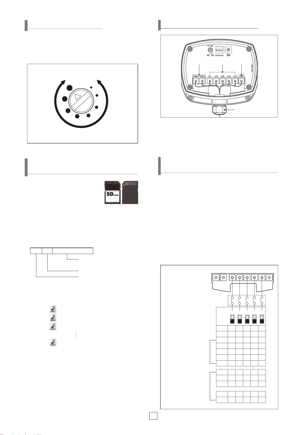
2. Insert the SD card into the SD card slot.
3. Set the No. 1 switch of the sound switch to ON to select external
sound.
- For more information, see page 4 ‘Sound Settings’.
4. Use the play mode setting switch to select 1, 3, 5, 7 or 8 mode.
- Mode 8 is a test mode which continuously plays channel 1.
(In this case, channel selection is disabled.)
- For more information, refer to page 4 ‘Play Mode Setting’.
5. To select a channel, use the terminal block in the back side of
the product to select one of the 5 user-dened sounds.
- For more information, please refer to page 7 ‘Bit Input - Playing
External Sound (SD Card)’.
1. Please refer to page 5
‘SD Card Specications and Sound
Saving Manual’
to see how to save sound les.
- Supports up to 30 user-dened sounds
2. Insert the SD card into the SD card slot.
3. Set the No. 1 switch of the
sound
setting switch to ON to select
external sound.
4.
Use the play mode setting switch to select one of the modes
between 2, 4, 6, or 8.
- Mode 8 is a test mode which continuously plays channel 1.
(In this case, channel selection is disabled.)
- For more information, refer to page 4 ‘Play Mode Setting’.
5.
Use the sound select switch to select the one of the 30 user-
dened sounds.
-
For more information, please refer to page 7 ‘Binary Input -
Playing External Sound (SD Card)’.
1. Set the No. 1 switch of the sound setting switch to OFF to select
the built-in sound.
- For more information, see page 4 ‘Sound Settings’.
2.
Use one of the sound setting switches 2, 3 and 4 to select one of
the 6 groups.
- For more information, see page 4 ‘Sound Settings’.
3.
Use the play mode setting switch to select one of the modes
between 2, 4, 6, or 8.
- Mode 8 is a test mode which continuously plays channel 1.
(In this case, channel selection is disabled.)
- For more information, refer to page 4 ‘Play Mode Setting’.
4.
Use the sound select switch to select one of the 30 built-in sounds.
- For more information, please refer to page 6
‘Binary Input -
Playing Built-in Sound’
.
■ When Using a Built-in Sound in Bit Input Mode ■ When Using an External Sound Source (SD Card) in Bit
Input Mode
■ When Using a Built-in Sound in Binary Input Mode ■ When Using an External Sound Source (SD Card) Source in
Binary Input Mode
When using a built-in sound When using an external sound (SD card)
Bit input Binary input Bit input Binary input
Organized into 6 groups of 5
sound tones for a total of 30 sound
tone options. Play one of the ve
sounds in each 5 group
Play one of 30 built-in sounds Play one of the 5 user-recorded
sounds
Play one of the 5 user-recorded
sounds
Operation Method and Setting