QOLSYS IQ PANEL 2 User manual

The Qolsys IQ Panel 2 is a 7” touchscreen built with an Android operating system,
providing full security and smart home functionality in an easy to use interface.
INSTALLATION MANUAL
Qolsys IQ Panel 2
Software Version 2.0.6

INTRODUCTION
ABOUT THIS GUIDE
QOLSYS CONFIDENTIAL AND PROPRIETARY
PAGE OF2 57
?
This document outlines the basic hardware specifications and software directions to
install and customize the IQ Panel 2. Note that the information presented is not
comprehensive, but is specifically dedicated to those menus, features, and systems
accessible solely to those with the proper installation code. Features accessible to
users and installers alike are outlined in the IQ Panel 2 User Guide. The information
contained is confidential and proprietary, and is solely owned by Qolsys Inc. Any
reproduction, modification or distribution without permission is strictly prohibited.
IQ Panel 2
Power
Supply
Table
Stand
INCLUDED IN BOX
SUPPORT

PANEL
ARCHITECTURE
Warning: This Product should be installed in accordance with the National Fire Alarm Code, ANSI/NFPA 72, (National Fire Protection Association,
Batterymarch Park,Quincy, MA 02269). Printed information describing proper installation, operation, testing, maintenance, evacuation planning, and repair
service is to be provided with this Product. In Canada the product shall be installed in accordance with the Standard for the Installation of Residential Fire
Warning Systems, CAN/ULC-S540.
Warning: For Canadian installations this Product and all sensors associated with it (collectively, the “System”) should be tested once a week. The test shall be
performed also with primary DC power de-energized. For recommended smoke detectors maintenance instructions refer to user manual associated with
compatible Qolsys model QS5110-P840 smoke detector.

PANEL OVERVIEW
INTERIOR
Panel Battery*
Image Sensor Radio
(Optional)
Z-Wave Plus
Radio
LTE Sim Card
“Tool-less”
Terminal Block
Tamper Switch
Cellular Antenna
The battery should NEVER be disconnected without following proper power-down procedures (page 120)
Failure to comply may result in data corruption, panel failure, and a void of the manufacturer's warranty
*CAUTION
QOLSYS CONFIDENTIAL AND PROPRIETARY
PAGE OF4 57
Siren
Security RF
Radio
Expansion Slot
Barrel Jack
Power
Image Sensor Antenna
Toggle Switch

INSTALLING
THE PANEL

INSTALLING THE PANEL
Insert your thumb or finger
under the opening on the
back cover and firmly pull up
to remove. This cover is not
needed for wall mount.
Press tabs on the bottom of
the panel and pull apart to
remove the back plate.
Mount to the wall using
appropriate hardware
ensuring it’s level.
1. Hang the front of the panel with
the hanging strap on the back plate
as shown above.
2. Make a small hole in the wall
through the bottom right mounting
hole and feed the white RF antenna
into the wall.
IMPORTANT: Not properly routing
the RF antenna in the wall will
greatly reduce RF sensor range.
If there is a gap on the top
because the panel did not
completely close, firmly pinch at
all 4 snap tab locations to
ensure proper closure. You will
hear a “pop” or “snap” sound
when pinched.
QOLSYS CONFIDENTIAL AND PROPRIETARY
PAGE OF6 57
WALL MOUNT OPTION
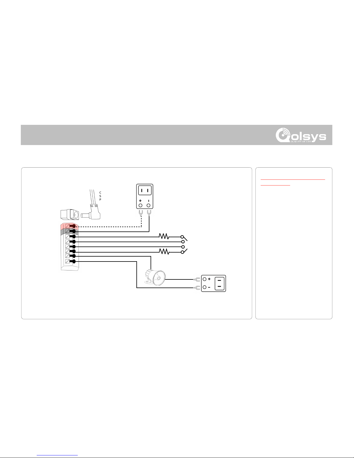
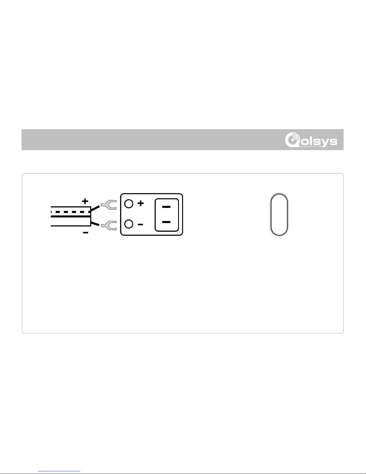
Connect your 5.0 - 5.5v DC Power
supply to the barrel jack or to the
(+/Red) and (-/Black) terminals if
using a custom length wire.
1. At a 60° - 90° angle seat the top
of the panel on the top 4 tabs of the
back plate. Ensure the tabs line up
with the grooves on the panel.
2. Swing the panel downwards to
close while feeding the antenna and
power wire in the wall.
1
2
1
2

INSTALLING THE PANEL
1. With the included power
supply and cable, plug the
barrel connector into the
jack next to the terminals as
shown above.
2. Route the cable under the
hook next to the battery.
3. Route the cable through
the strain relief opening.
Replace the cover by
inserting the top first, then
while making sure the
cable passes under the
opening firmly press down
on the bottom until the
cover “snaps” into place.
QOLSYS CONFIDENTIAL AND PROPRIETARY
PAGE OF7 57
TABLE STAND OPTION
Insert your thumb or finger
under the opening on the
back cover and firmly pull
up to remove.
1
2
3
Insert table stand dowels
into the 2 upper keyholes.
Slide the stand firmly
upwards until you hear a
“click” from each side.

INSTALLING THE PANEL
WIRING DIAGRAM
QOLSYS CONFIDENTIAL AND PROPRIETARY
PAGE OF8 57
NOTE: Use only UL/ cUL listed
external siren in UL/cUL listed
installations. Rating:12vDC/
300mA
NOTE: Inputs are used only
for Burglary applications.
IMPORTANT IF USING CUSTOM
LENGTH WIRE: Use 18AWG wire
no longer than 25ft to ensure
sufficient power is received at the
panel.
NOTES
5.0 - 5.5vDC IN
GND
SENSOR 1
GND
SENSOR 2
GND
EXT SIREN
GND
WARNING!
Use 5.0 -
5.5v Power
Supply ONLY
4.7k
4.7k
CLOSED LOOP
CIRCUIT
-
+
EXT SIREN:
Maximum Voltage: 12vDC
Maximum Current: 300mA
5.0 - 5.5vDC IN
BARREL JACK
BARREL JACK FOR
USE WITH SUPPLIED
BARREL CONNECTOR
CABLE ONLY.
STRIPED WIRE IS
POSITIVE (+)

INSTALLING A DAUGHTER CARD
IMAGE SENSOR DAUGHTER CARD
QOLSYS CONFIDENTIAL AND PROPRIETARY
PAGE OF9 57
Before powering on the panel, install the Image Sensor
Daughter Card if planning to use an Image Sensor.

INSTALLING THE PANEL
IMPORTANT IF USING CUSTOM LENGTH WIRE:
Use 18AWG wire no longer than 25ft to ensure
sufficient power is received at the panel.
QOLSYS CONFIDENTIAL AND PROPRIETARY
PAGE OF10 57
Press and hold the power button on
the right side of the panel for 3
seconds to power up.
POWERING THE PANEL
Connect power supply.
WARNING! Use 5.0 - 5.5v Power Supply ONLY
If using the provided cable, the “striped” wire is (+)

PROGRAMMING

PROGRAMMING
SETTINGS TRAY
QOLSYS CONFIDENTIAL AND PROPRIETARY
PAGE OF12 57
To access the Settings tray swipe down on the bar at the top of the screen. The
Settings tray has quick access to system, battery, wi-fi, bluetooth & cellular status as
well as volume control, brightness and other quick settings.
Swipe down
for access
FIND IT

The Settings page allows quick access to various simple
features & settings that do not require the protection of a
Dealer, Installer or Master code to be changed.
PROGRAMMING
FIND IT
Swipe down
for access
SETTINGS
SETTINGS
Setting
Description
Display
Adjust brightness, font size & 12/24 hour time
SD Card
Mount, unmount and manage SD Cards that are installed in a panel
Weather Temperature
Toggle between Farenheight and Celcius
Status
View the "Current Status" of security sensors: Zone #, Name, Status
(Open, Close, Active, Idle, Tamper, Failure), Battery and sensor History. Also
view “Alarms” and “History” for security sensors globally
Z-Wave Device Status
View the "Current Status" of Z-Wave devices: Name, Type, Status (Normal,
Failure), and Battery. Also view “Alerts” and “History” for Z-Wave globally
Other Z-Wave Devices
Shows Z-Wave devices that are learned into the panel but that are not part
of the main user interface (Lights, Locks, Thermostats & Garage Doors)

PROGRAMMING
FIND IT
Swipe down
for access
SETTINGS
SETTINGS
Setting
Description
Automation
Add, Edit or mange local lighting automation rules. These rules are
separate from any cloud based rules that may be set through Alarm.com.
Examples of possible rules are as follows:
-Night: Turns light on at 7pm and off at 6am
-Evening: Turns light on at 7pm and off at 11pm
-Front Door: Turns light on for 15mins when Front Door opens (must have
a sensor with the default quick name “Front Door” added in the panel)
-Doorbell: Turns light on only after 7pm for 15 min. when Doorbell is
activated (must have a sensor with the default quick name “Doorbell”
added in the panel)
Activity Monitor
Activity Monitor allows access to disarm sensors that are programmed as
24 hours zones, such as Sensor Groups 8, 9 & 25. A valid Master, User or
Guest code is required to control 24 hour activity sensors. 2 options are
provided:
-Quick Access: 300 second temporary access
-Deactivate: Disarms 24 hour sensors until they are re-activated
manually
Advanced Settings
Access advanced settings & programming. A valid Dealer (default 2222),
Installer (default 1111) or Master Code (default 1234) is required
QOLSYS CONFIDENTIAL AND PROPRIETARY
PAGE OF14 57

To access the Advanced Settings menu pull down the Settings
tray at the top of the screen, select “Settings” and then
“Advanced Settings”. Enter your dealer, installer or master
code. The code used to enter Advanced Settings determines
the level of access.
PROGRAMMING
FIND IT
QOLSYS CONFIDENTIAL AND PROPRIETARY
PAGE OF15 57
Swipe down
for access
SETTINGS
ADVANCED SETTINGS
ENTER CODE (1111, 2222)
ADVANCED SETTINGS
INSTALLER MENU (1111)
DEALER MENU (2222)

PROGRAMMING
System Test/Cellular Test
Test the panel’s built-in cellular radio connection. You must first activate the
radio through Alarm.com prior to running this test. Cell signal strength is only
available after the test has been ran successfully.
To begin the test press “Start” and watch for the results on the screen.
QOLSYS CONFIDENTIAL AND PROPRIETARY
PAGE OF16 57
CONNECTING TO ALARM.COM
FIND IT
CELLULAR TEST
SYSTEM TESTS
Swipe down
for access
SETTINGS
ADVANCED SETTINGS
ENTER CODE (1111, 2222)

CUSTOMIZATION
To connect to a Wi-Fi network, follow
the steps below:
Touch Advanced Settings (Installer Code)
Then touch “Wi-Fi”
Available networks appear in a list. Touch the
desired network and use the keyboard to type
the password (if required)
QOLSYS CONFIDENTIAL AND PROPRIETARY
PAGE OF17 57
Enable Wi-Fi if not already active
Swipe down from the top menu bar
and select settings.
CONNECTING TO WI-FI
FIND IT
WI-FI
Swipe down
for access
SETTINGS
ADVANCED SETTINGS
ENTER CODE (1111, 2222)

MAINTENANCE
Upgrade Software
Upgrade the panel’s software version using Wifi or an SD Card.
UPGRADE SOFTWARE
FIND IT
UPGRADE SOFTWARE
Swipe down
for access
SETTINGS
ADVANCED SETTINGS
ENTER CODE (1111, 2222)
Setting
Description
Upgrade Using Network
Search the network for updates and install new software Note:
for UL/cUL, remote software uploading is not allowed
Upgrade Using SD Card
Search an inserted SD Card for updates and install new software
Downgrade Using Network
With the proper Patch Tag the system can be properly downgraded
Patch Tag
A code corresponding to a specific software update on the server
Automatic Upgrade
Allow the panel to update it’s software as new versions become available
Note: For UL/cUL, automatic upgrade is not allowed
Automatic Background Check and
Download
Allows the panel to check for new software in the background and
download it to local storage so that it can be applied at a later date. Default
Enabled
Automatic Upgrade Interval
Determines interval the IQ Panel 2 will look for software update. Available
options are Every Night, Once a Week, Once a Month. Default Every Night
Note: Proper maintenance requires prompt administration of any software updates

PROGRAMMING
QOLSYS CONFIDENTIAL AND PROPRIETARY
PAGE OF19 57
Daughter Cards Test
Tests the integrity of installed daughter cards . Slots not populated will be
“greyed” out and inaccessible to test.
Select “Run” on an
individual available card
to start the test. In some
cases the test may take
several minutes after
which the panel will
show a result of a “Pass”
or “Fail”.
If the test results in “Fail”
double check the
daughter card
connection, reboot the
panel and rerun the test
again.
DAUGHTER CARD TEST PRIOR TO PROGRAMMING DEVICE
FIND IT
DAUGHTER CARDS
TEST
SYSTEM TESTS
Swipe down
for access
SETTINGS
ADVANCED SETTINGS
ENTER CODE (1111, 2222)

PROGRAMMING
QOLSYS CONFIDENTIAL AND PROPRIETARY
PAGE OF20 57
Swipe down
for access
SETTINGS
ADVANCED SETTINGS
ENTER CODE (1111, 2222)
FIND IT
INSTALLATION
INSTALLATION
If Dealer Contact info is not previously filled out or pushed from Alarm.com, a pop up is
generated when accessing the “Installation” icon, requiring that dealer contact information
to be entered. This information is used to populate the “Contact Us” tab in the Message
Center. Note: Company Name and Company Phone Number are required and must be filled out to
continue with panel programming.
Other manuals for IQ PANEL 2
3
Table of contents
Other QOLSYS Touchscreen manuals