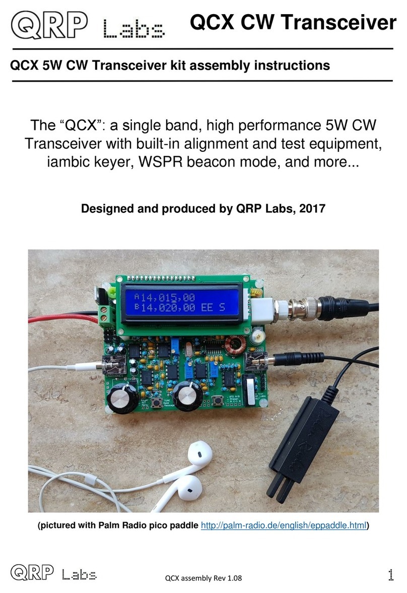
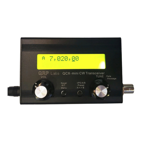
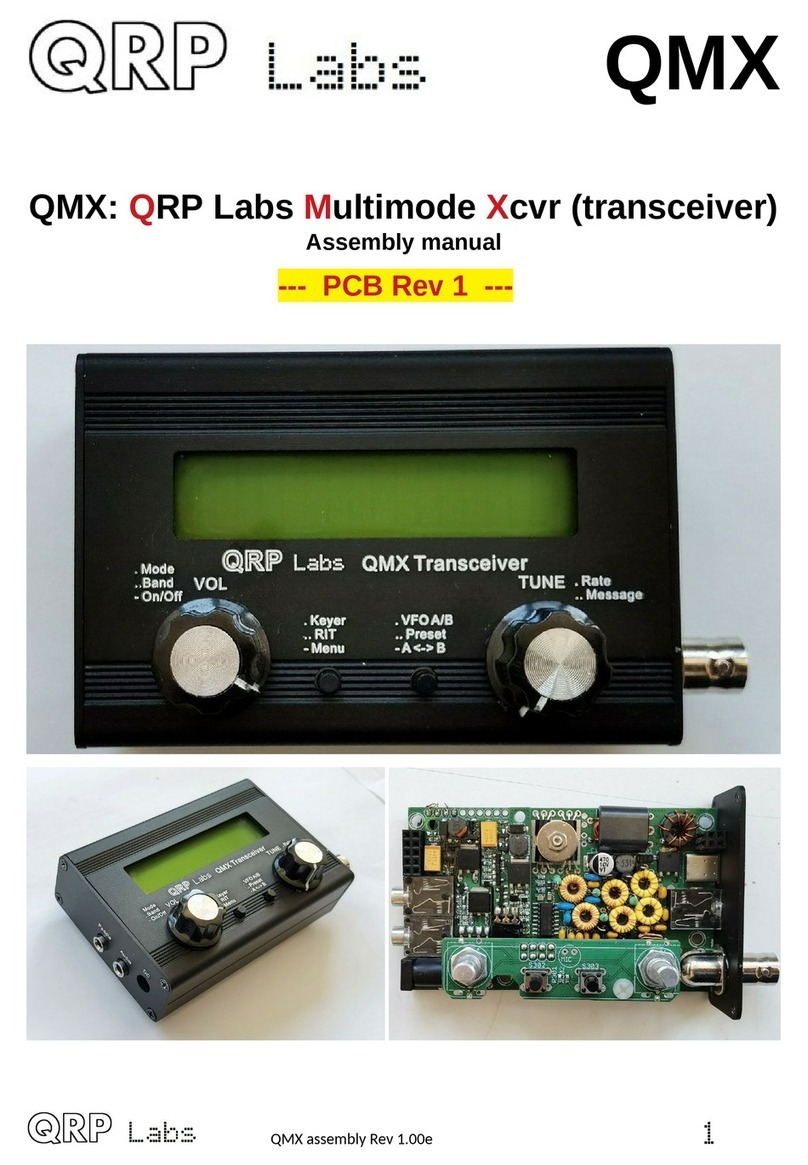
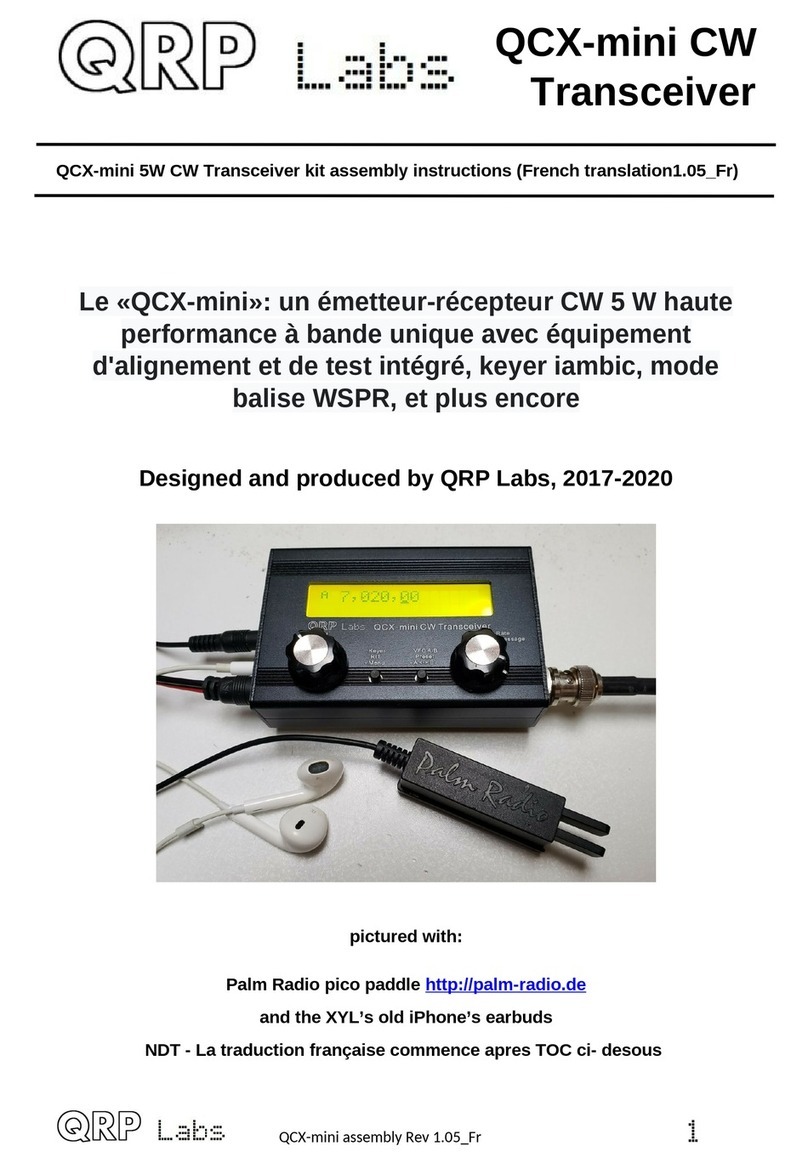
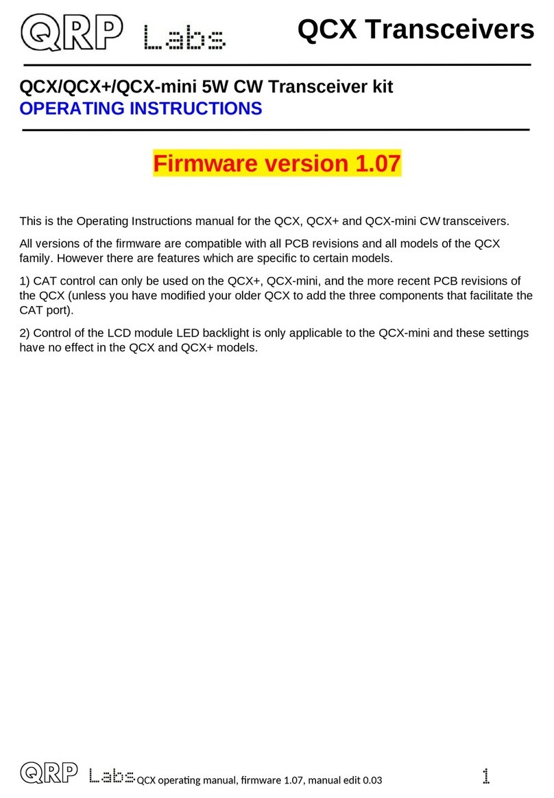
QRP Labs QDX User manual

www.arrl.org QST March 2023 41
Reviewed by Charles Powell,
NK8O/VE3ISD/5H3DX
nk8o@arrl.net
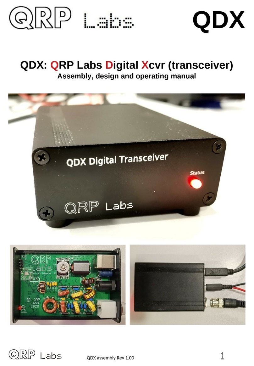
The QRP Labs QDX Digital Transceiver is a low-
power, low-cost radio for digital operations. The
reviewed unit covers ve HF bands — 80, 60, 40, 30,
and 20 meters — and the maximum power output is
5 W, with support for digital modes only. It comes in a
kit to be built, and you can buy a fully assembled unit
for an extra $45. See Figure 1 for the kit parts packag-
ing. The printed circuit board (PCB) comes with pre-
installed surface-mount device (SMD) components
(Figures 2 and 3 show each side of the PCB). It includes
an embedded software-dened receiver (SDR), 24-bit
48 kilo samples per second (kS/s), a USB sound card,
CAT control, and a synthesized VFO with TCXO refer-
ence. The QDX transmits a single, clean output signal,
as it is not an SSB modulator with associated unwanted
sideband and residual carrier, or intermodulation due to
amplier non-linearity (more on this later).
The QDX is suitable for single-tone operations. It is
reported on the QDX forum that successful RTTY oper-
ation has been accomplished. It is not suitable for CW
operation using digi or similar programs. It is my
understanding that there is no waveform shaping that
would prevent key clicks. Modes that require multiple
simultaneous tones, such as Winlink, are not possible
with the QDX. Also, the QDX is not capable of phase-
shift keying, such as PSK31. Per the product descrip-
tion,
QDX is suitable only for single tone FSK modes,
which covers the majority of digital modes in use today.
This includes everything in WSJT-X, JS8Call, some
digi modes e.g. RTTY, Olivia and more. QDX is not
suitable for on/off keyed modes such as CW because it
does not have click-reducing RF envelope shaping; fur-
thermore, it is not suitable for phase shift keyed modes
such as PSK31 or modes involving multiple concurrent
tones such as WinLink.
Description and Kit Assembly
While it does require a computer, the unit has only four
connections on the rear panel: an antenna BNC port, a
power connection, a 3.5-millimeter PTT, and a single
Product Review
Bottom Line
The QRP Labs QDX is a low-cost digital trans-
ceiver with a clean RF output signal for the
supported digital modes. Setting it up is fast
and easy, perfect for portable and permanent
installations.
Pascal Villeneuve, VA2PV
,
QRP Labs QDX 5-Band HF QRP
Digital Transceiver
Figure 1 — The QDX
kit with parts packaging.
USB type B port that handles both CAT control and
audio (see Figure 4). When all the necessary physical
connections are made, the unit becomes a “black box”
that requires no other user intervention.
Since Revision 3 (Rev3, now Rev4), QRP Labs added a
standard 3.5-millimeter plug for an external PTT con-
nection that can be used without modication between
the QDX and the QRP Labs 50 W PA. The PTT output
can also be congured for use with any other amplier.

42 March 2023 QST www.arrl.org
Figure 3 — The rear view of the QDX’s PCB.
Figure 2 — The front view of the QDX’s PCB.
I have considerable experience with QRP Labs prod-
ucts. I assembled at least eight original QCX models,
repaired several more, and built a QCX+. The QRP
Labs instruction manuals are clear, they contain con-
cise technical descriptions, and they are generally easy
to follow. The QDX documentation is no exception. It is,
perhaps, among the easiest of the QRP Labs kits to
assemble. My assembly time was no more than a few
hours.
Assembly is straightforward, and the parts count is low.
Most of the board is pre-populated with the SMD com-
ponents, so the user doesn’t need special tools to com-
plete the kit. There are 16 through-hole capacitors, six
diodes, four transistors for the nal amplier, an LED, a
transformer, and a series of toroids to wind and install.
Finally, a few connectors complete the build. Depending
on your level of experience, the kit can be assembled in
a few hours. There is only one construction option, and
that is whether to build the device to operate on 9 or
12 V dc. To quote the operating manual, “No test equip-
Figure 4 — The rear panel of the QDX.
ment is required to build, align, and operate this digi
modes transceiver. There are no alignment tasks.”
For more details, you can download the manual from
the manufacturer’s website (www.qrp-labs.com/
qdx.html).
Linux (Xubuntu 22.04) is my operating system of choice.
But as stated on the manufacturer’s website, the drivers
for these types of audio devices should be already pres-
ent on your computer if you are using macOS, Linux, or
Microsoft Windows 10 or 11. If you are using older ver-
sions of Windows, then you need to install a driver for
the virtual COM port (audio and USB ash drivers are
already present, even on older versions of Windows).
The details can be found in the QDX manual. I made
the connection between the QDX and my laptop via a
USB A/USB C cable. Linux immediately recognized the
built-in sound card, and it was easy to select the correct
sound settings in WSJT-X. The serial device followed
the typical naming scheme for Unix-like systems. The
serial port test conrmed operation immediately, and
after a brief check I was on the air. I selected the
KENWOOD TS-440S conguration for CAT settings in
WSJT-X. The sound card appears as ALSA_INPUT.
USB-QRP-LABS_QDX_TRANSCEIVER-02.ANALOG-
STEREO and ALSA_OUTPUT.USB-QRP-LABS_QDX_
TRANSCEIVER-02.ANALOG-STEREO, respectively, for
audio input and output. With the QDX designation in the
sound card description, there is little possibility of
making a mistake in selecting the device. The serial
port appears as /DEV/TTYACM1 on my laptop. I have not
connected the radio to a Windows or Mac computer to
date. Most importantly, the radio was not designed
around a single operating system.
On the Air
With many hours of operation behind me, I can say with
certainty that this transceiver is unparalleled in ease of
operation within the scope of my experience. The
radio’s front panel has no controls and only a single

www.arrl.org QST March 2023 43
I use the transceiver primarily for
portable operations, as I am an avid
activator for both World Wide Flora
and Fauna and Parks on the Air®
programs. Rapid deployment is a
distinct advantage for eld operations,
and the QDX greatly facilitates this.
Previous eld setups included mul-
tiple peripherals, careful adjustment of
sound and drive levels, and many
extra wires that were easily miscong-
ured. The setup of the QDX is nearly
foolproof. Due to the nature of propa-
gation, portable operations, and the
parks programs, the majority of my
operating has been on 20 meters. I’m
sure other bands would work well, but
I typically do not spend a lot of time
away from 14074 kHz. I have, how-
ever, tested the transceiver and made
a few contacts on other bands.
Operating voltage and power output
are supposed to be determined by the number of turns
on the secondary winding of transformer T1. I chose the
12 V operation voltage, although I nd that my transmit-
ter is a bit more optimistic than one might like. The max-
imum recommended output is 6 W, and my transceiver
puts out nearly this much and more on several bands.
So far, I haven’t encountered any difficulties, but there
could be a replacement for the BS170s transistor in the
future. My battery of choice is LiFePO4, and the voltage
is a very steady 13.2 V under normal operating condi-
tions. The power output of the QDX is strictly a function
of input voltage and not related to audio drive. Manipu-
lation of the input voltage in the eld does present cer-
tain problems. The recommended input of 12 V can be
obtained by placing a diode inline with the power source
(see Table 1). I may try a LiPO4 pack (about 11.1 V) to
see if that drops the power output to a more acceptable
level.
There is a jack for operations with an external power
amplier, but I have not found it necessary to move to
QRO operations. I have made thousands of contacts
with plenty of DX using low power and a good antenna.
An LED indicator shows that the radio is powered up. In
transmit, the LED has a medium blink rate. It shows a
fast blink rate on boot-up, or very slow and steady blink
rate if it is in the rmware upgrade mode. Boot time is
less than 1 second, but the fast LED will blink for 5 sec-
onds. For portable operations, setup takes a little longer
than setting up the antenna. There are no settings to
ddle with. The transmit level in WSJT-X does not affect
USB cable, power, and antenna connection on the
back of the radio. While no adjustment or alignment is
needed, it’s possible to access conguration and test
menus. To access these features, you will need to use
terminal software like PuTTY or Minicom, which will give
you access to several menus within the radio. The rm-
ware is upgradable. The radio seems exceptionally
stable, likely due to the TCXO that controls the refer-
ence oscillator.
There are no relays within the radio. All switching is
done with PIN diodes. I have used the radio only for
FT4, FT8, and JS8Call, but operations with these
modes have been nearly trouble-free. Modes that will
work shift frequencies one at a time. The QDX cannot
be used for phase-shift keying, multi-tone modes, or
CW. It is reported to work with RTTY (with some com-
promises), DominoEX, and Olivia.
There was one instance of a brief failure, but it was
really a computer operating system problem, and it had
nothing to do with the QDX. The USB port designation
changed from /DEV/TTYACM1 to /DEV/TTYACM0, but this
was easily remedied in the eld. This can happen with
any operating system. With Linux-based systems it is
possible to make a permanent port assignment to avoid
this problem. While I have had some experience with
Mac OS X, it has been quite a while, and I am unfamil-
iar with recent changes within the OS. I also have very
little recent experience with Microsoft Windows.
Table 1
QRP Labs QDX HF Digital Transceiver (Rev4)
Manufacturer’s Specifications Measured in the ARRL Lab
Frequency coverage: 80, 60, 40, As specied.
30, and 20 meters.
Power requirement: At 12 V dc: transmit, 0.9 A;
9 V or 12 – 13 V dc with modication. receive, 166 mA.
Receive
Modes of operation: Digital only. As specied.
Transmitter Transmitter Dynamic Testing
Power output: Up to 5 W. At 12 V dc: 3.5 MHz, 4.5 W; 5.3 MHz,
4.8 W; 7 MHz, 4.2 W; 10.1 MHz,
5.4 W; 14 MHz, 5.5 W.*
Spurious-signal and harmonic suppression: Typically >52 dB; worst case,
Not specied. 44 dB (60 meters). Complies with FCC
emission standards.
Size (height, width, depth, including protrusions):
1 × 2.48 × 3.49 inches. Weight: 0.30 pounds/(135 grams).
*RF power output was 3.0 W on 14 MHz with 9 V dc input voltage.
44 March 2023 QST www.arrl.org
power output, and it is recommended to simply leave
the transmit power at the maximum setting. I reduced
the computer’s audio input drive to keep the receive
level indicator out of the red, but that was the only
adjustment needed in my conguration.
My portable operations have taken me very far aeld, at
least through a swath of the central United States. My
favorite portable operating position is from a picnic
table, although the small size of the QDX makes it easy
to set up nearly anywhere. I have a portable aluminum
table that also works well. It is rare that I operate exclu-
sively in digital modes, so I need enough room for a CW
transceiver. I may be something of a heretic, but I rarely
operate QRP when I am activating a park unless there
is a considerable hike involved. Then the station is as
light as possible. My “tailgate” and picnic table opera-
tions are usually accompanied by a Yaesu FT-991A for
CW. There is always plenty of room for the QDX. Keep
in mind that the QDX requires some sort of computer,
although there are many congurations that can be
used for this purpose. A Raspberry Pi, which is about
the same size as the QDX, could be linked wirelessly to
a tablet or iPad, making for a compact and versatile
setup.
Hans Summers, G
Ø
UPL, founder of QRP Labs and the
designer of the QDX, provides a better technical
description of the operation of the radio, but here’s my
take. As a musician, I understand the term “transposi-
tion.” To transmit, the radio uses an analog-to-digital
conversion of the audio input signal, which is sampled.
The sample of each audio frequency is then “trans-
posed,” or transformed, directly to appropriate RF fre-
quencies. These are not sideband signals injected to
produce a suppressed carrier SSB transmission. The
transmitter produces pure frequency shift keying without
any spurious mixing products.
The receiver is an SDR that uses an intermediate fre-
quency for the nal extraction of the tones — rst in
digital form, then fed as audio to a built-in sound card,
and nally sent via USB to a computer. Anecdotally, the
receiver passband is nearly devoid of noise. In very
unscientic terms, the radio doesn’t seem to “hear”
much of anything aside from the intended signals. This
may, in part, have to do with portable operations, but
even still I nd that, compared to other QRP FT4/FT8
setups I have used, the signal-to-noise ratio appears to
be much better with the QDX. Compared to other QRP
setups, my experience is that the QDX hears well
enough that there is bigger spread in SNR readings,
and because the QDX hears so well, a reply with the
other station being unable to hear it seems to be more
frequent than with other radios I have used.
The QDX does an excellent job of leveraging the modes
available in WSJT-X and several other popular modes.
Conclusion
Overall, the QDX is an excellent transceiver. It is com-
pact, easy to use, and nearly foolproof. I highly recom-
mend purchasing the case unless you are highly skilled
at fabricating your own enclosures, or if you have a 3D
printer, as some templates are available online. The
radio is a worthwhile addition to my go-box for portable
operations, but it would function equally well as a dedi-
cated radio in the shack.
Manufacturer: QRP Labs, www.qrp-labs.com. Avail-
able in two versions at the same price: 80, 60, 40, 30,
and 20 meters (the reviewed unit), and the new 20, 17,
15, 12, and 10 meters. Price: $69 for the kit version, and
$20 for the optional enclosure; an extra $45 for the
assembled version.
Signal Generators
Bottom Line
There are aordable signal generators out
there that may be a good starting point for
someone new to this kind of tool. For the most
advanced users, or if you want to maximize
your investment right from the start, it may be
best to purchase a unit that also comes with a
calibration certificate with traceability.
Reviewed by Paul Danzer, N1II
n1ii@arrl.net
You can no longer buy a signal generator like you used
to. Although some manufacturers divide their products
into two classes — analog signal generators whose pri-
mary output is CW (sine wave), and vector or digital sig-
nal generators whose primary output is complex digital
waveforms — most analog signal generators can gener-
ate square, triangular, and various digital waveforms.
Most digital signal generators also can generate CW.

www.arrl.org QST March 2023 45
Table 2
Signal Generators Manufacturers’ Specifications (not tested in the ARRL Lab)
Models JDS2900 and SDG 1032X Rigol DG1062Z
JDS6600-60M
Display 2.4-inch TFT color LCD 4.3-inch TFT color LCD 3.5-inch TFT color LCD
Max frequency of sine wave 60 MHz 60 MHz 60 MHz
Max frequency of square wave 25 MHz Two channels 30 MHz Two channels 60 MHz
Max frequency of triangular wave 25 MHz Not specied Not specied — ramp 1 MHz
Max frequency of pulse waveform 6 MHz 12.5 MHz 25 MHz
Max frequency of TTL waveform 6 MHz For custom waveforms 30 MSa/S 25 MHz, custom 25 MHz
Pulse width range 25 nS to 4000 seconds 32.6 nS to 1000 ks 16 nS to >1000 seconds
Square wave rise time ≤10 nS <4.2 nS <10 nS
Square wave jitter Not specied 300 ps+ 0.05 ppm of period 2 ppm +20 pS at <5 MHz
Frequency stability ±1 ppm/3 hours Not specied ±1 ppm
Each waveform length 2048 points 16 kpts 16 Mpts per channel
Waveform sampling rate* 266 MSa/S 150 MSa/S 200 MSa/S
Waveform vertical resolution 14 bits 14 bits 14 bits
Operating temperature 0 – 40 °C 0 – 40 °C 0 – 50 °C
Waveform types See text See text See text — 160 + arbitrary design
*Mega samples per second
The older-generation generators were capable of
CW-only output. Drifting due to heat (vacuum tubes
were very good at making heat) and drift in calibration
were major problems, as was the aging of components
with time. These problems drove the size and mechani-
cal design, as well as the type of oscillator used in the
unit. In turn, these considerations resulted in limits to
the frequency range available with multiple range switch
positions.
Nearly all such units had only one output channel and
had to be recalibrated periodically. For high-accuracy
frequency generation, many lab applications required a
stand-alone frequency counter, which had its own sta-
bility problems.
Finally, some models became available at a low or
moderate cost by sacricing performance in the areas
just listed as problems. Homebrewed models requiring
selected parts often appeared as an exercise in art
rather than electronic design!
In this review, I look at ve different signal generators.
There are major differences in the design and resulting
capabilities between today’s models and those of sev-
eral years ago, before the availability of digital integrated
circuits and microprocessors.
Digital Synthesis
Rather than being concerned with inductance-to-capac-
itance ratio and the temperature coefficient of capaci-
tors, most generator manufacturers today look at a
repetitive waveform as a set of points. Each point has
an amplitude, and the more points read and convert to
an analog voltage (or digital waveform) per second, the
smoother the output waveform. Selecting a waveform to
generate is really selecting a point-generating program.
Picking the frequency selects how fast the points read
out. Usually, a microprocessor controls the operation,
and a digital readout (or a counter on the front panel)
provides the frequency value being generated.
Each manufacturer has its own techniques in the design
of the unit. For example, interpolation, smoothing, or
encoding may be used to ll in between generated
points. The digital number display may be offered as a
freestanding counter, as an extra feature. When looking
for a generator to use in your station, you may nd that
several units available online, especially imported units,
have similar front panels and specications. These
similarities may lead you to wonder if they are not the
same unit with a different name plaque! I selected a
cross section of available generators for this review. At
the low end are several similar units, and at the higher
end are those with more availability or better capabili-
ties. Table 2 summarizes the manufacturers’ main
specications of the tested units.

46 March 2023 QST www.arrl.org
JUNTEK JDS2900
Figure 5 – The JUNTEK JDS2900 left side view, with the ON/OFF
switch, the 5 V dc power connection, and the USB connector.
show a square wave, but adjusting the amplitude of
the square wave will be reected in the number on the
screen, not the height of the picture. A white illuminated
dot on the screen tells you which item is active and will
respond to control changes.
The round knob changes the digit of whatever is being
changed by your selection. Suppose the amplitude is set
to 3.500 V and the 5digit is shown with a red marker.
Rotating the round knob clockwise will change the
5 value to 6, 7, 8, 9 in sequence. To jump quickly from
one digit place to the next, you can use the arrow keys.
The selected output is shown on the right side. To make
changes on channel 1, press the 1button. To make
changes on channel 2, press the 2button. The associ-
ated LEDs remind you what selection you made when
illuminated.
It is easy to forget where you are when making complex
selections. To reset, slide the power switch off — this
may be drastic, but it might be the only way to get back
to where you want to select a signal.
There are 20 selectable waveforms from the front panel.
This review covers only the front panel capabilities;
there are 14 arbitrary programmable waveforms that
can be set up and stored for immediate recall through a
computer interface.
Available Waveforms
Per the list in the Quick Guide, the following xed wave-
forms are selectable: sine, square pulse (with adjustable
width and period), triangular wave, partial sine wave,
TTL/CMOS wave, adjustable DC level, half sine wave,
positive- and negative-going staircase wave, noise
wave, up exponential rise, down exponential, and sev-
eral others. There are more than 14 programmable slots
for your choice of non-standard waveforms that can be
stored.
A full explanation of each of the buttons for each mode
or waveform would take several pages of instruction,
This almost pocket-sized waveform generator front
panel is approximately 4 × 1.5 × 4 inches. It has two
modes of operation: functions that can be called up and
their settings adjusted for the front panel, and functions
that can be set up and adjusted only by software
installed on a personal computer or laptop.
The package comes with the basic unit, a wall wart
power supply, a mini CD, and a set of cables. The
quick-start booklet included in the package is minimal;
there is a full set of instructions and descriptions on the
CD. The le is named DDS_SETUP. Drag it to your desk-
top and uncompress with a tool like 7Zip or another
uncompressing tool. Open the following folders/les in
this order: SIGNAL GENERATOR SOFTWARE, ENGLISH,
and QUICK GUIDE. The Quick Guide PDF has both the
full instructions and a list of the manufacturer’s speci-
cations.
Inputs and Outputs
The left side panel has a socket labeled DC5V that
mates with the cord from the power supply. Next to it is
a USB (type B) socket for connection to a PC. Finally, to
its right is the unit’s ON/OFF switch (see Figure 5).
On the right side are four BNC connectors labeled
TTLIN, EXTIN, CH1, and CH2. The last two have LEDs to
indicate which channel is active (it may indicate that
both are active). Unfortunately, the lettering for these
four connectors may be difficult to see under poor light-
ing conditions.
The mini CD has all the buttons on the front panel
shown in a pictorial with callouts of their names or func-
tions. Not labeled are the two arrow keys just below the
single rotary knob (to be described later).
Front Panel — Watch the Numbers, Not the Picture
For the most part, the waveforms on the front panel
vary only with major changes in selection. For example,
pressing the WAVE button to select a square wave will

www.arrl.org QST March 2023 47
which is exactly what can be found in the Quick Guide.
As an example, if you want a 3.1 V half sine wave with a
2.5 V offset, a frequency of 18 MHz, and output on
channel 1, start with the turn-on screen, as shown in the
lead photo of this unit, and press the channel 1 and 2
buttons until the display shows channel 1 on and chan-
nel 2 off. The channel screen should also have a white
dot on the top left and no such dot on the screen next to
the channel 2 legend. Select the waveform by pressing
WAVE and the SINE selection on channel 1, and it
should go red.
To select the waveform, press WAVE and then rotate the
round knob until the legend says HALF WAVE. By press-
ing the frequency button, the value is selected by using
the left arrow key to move the leftmost digit to a 1. Next,
press the right arrow key so the second digit is selected,
and rotate the round knob until the second digit reads
18. Because you want a frequency of exactly 18 MHz,
use the arrow keys and round knob to set the rest of the
digits to 0.
Finally, press the AMPL button followed by the arrow
keys and the knob to select an amplitude of 3.1 V. The
remaining item is the offset; press the OFFS button
again followed by the arrow keys and knob so the OFFS
legend on the screen reads the desired 2.5 V.
This sequence is typical for selecting a waveform from
the front panel. The vertical line of buttons selects the
item you want to adjust; the keys to the right have indi-
vidual results.
Compare a Couple of Numbers
As described earlier, the output waveform is a set of
programmed values coming out as a voltage whose
value over time is made up of these points generating
serially. According to the manufacturer, each waveform
(presumably of a repetitive waveform) can consist of
2,048 points. The waveform sampling rate is stated as
266 mega samples per second (MSa/S). These values
provide the limit for how accurate (or “smooth”) the
output waveform will be. Because a digital-to-analog
converter (and perhaps analog buffers) may be part of
the design, these numbers are limits, with the actual
specied values given by mode and setting, as appro-
priate, in the instruction manual.
Another number listed in Table 2 is the waveform verti-
cal resolution (14 bits, or 214, which is equal to 16384
counts). Again, the actual specied accuracies in ampli-
tude are given in the instruction le on the mini CD.
A Few More Keys
A few of the front panel keys are not discussed in the
previous example. In brief, they are: MEAS (switches
between measurement mode and a count function),
MOD (controls modulation mode interface), SYS
(switches between system selections, such as sounds,
brightness, and save current settings), and OK (controls
on/off for channels).
Several pages of instruction on the use of these buttons
are again found in the Quick Guide.
In Summary
When I received this unit, I was not very impressed. It
rattled — there was a screw loose and bouncing around
in the enclosure. Fortunately, it took only a few minutes
and four screws to open the enclosure and drop out the
loose hardware. Nothing else was loose, so after closing
it up, I proceeded with testing. The time it took to nd the
instruction le was also not impressive — it was located
several steps from the main le, and a RAR decompres-
sion was needed to traverse the le structure.
What was impressive was that once you turned it on
and tried to use it, you did not need many instructions.
Most functions are self-explanatory, and the response
to the labels was 100% for most direct functions. I ran a
number of quantitative checks. I did not list them here,
because the instrumentation I used, while typical of
many ham workbenches, was not demonstratively
accurate enough to prove the unit calibration. Certainly,
all were within 5 – 10%, but how much of each was due
to the unit and how much was due to the measuring
instruments cannot be determined.
Manufacturer: Hangzhou Junce Instruments Co.,
Ltd. (Juntek), No. 18, Xiyuan 1st Road, Xihu District,
Hangzhou City, Zhejiang Province, China, www.
junteks.com. Price: $99.98. Available at www.
amazon.com.

48 March 2023 QST www.arrl.org
Figure 6 – The SeeSii JDS6600 rear panel.
SeeSii JDS6600-60M
The documentation for the two models is slightly differ-
ent. The JDS2900 comes with both a mini CD and a
small quick-start booklet, and the JDS6600 comes with
a larger instruction summary book. The CDs are similar,
and the company name (Hangzhou Junce Instruments
Co., Ltd.) is the same. Because the same Quick Guide
apparently holds for both models, the manufacturer’s
host name on both PDF les holds for both JUNTEK and
SeeSii — not an unusual situation for an electronic de-
vice imported from the Far East. While the units appear
to be electrically similar, notice the price difference.
Manufacturer: SeeSii. Price: $139.99. Available at
www.amazon.com.
SIGLENT SDG 1032X
If you have ever searched online for an item from a
conglomerate supplier such as Amazon, you have prob-
ably found a web page that hosts several similar items,
from which you have to pick one. In order to compare
two similar signal generators, I selected the JDS2900
(reviewed earlier) and the JDS6600.
Their similarities become obvious when you notice that
the Quick Guide supplied with the JDS2900 does not
list the several models of the JDS2900, but lists the
models of the JDS6600. The JDS2900 comes from a
company called JUNTEK, and the JDS6600 comes
from a company called SeeSii.
There is a mechanical difference between the two.
The SeeSii lead photo shows the front panel of the
JDS6600. The layout is different from the JDS2900, but
the controls are similar. The biggest difference is the
size; the JDS2900 is approximately 4 × 1.5 × 4 inches,
while the JDS6600 is approximately 7.6 × 2.7 × 7 inches.
The location of the connectors is also different. The
JDS2900 has connectors on both sides. The JDS6600
has two channel outputs and the measurement port on
the front panel, and the dc connector, a USB type B
port, and a TTL connector on the rear (see Figure 6).
The TTL connector on the JDS6600 is a rectangular
10-pin polarized male, while the JDS2900 uses a BNC
connector.
The front panel of this industrial-strength waveform
generator is labeled “Easy Pulse,” and many of its func-
tions are easy to set up, customize, and use. There are
other capabilities for which you may need the online
documentation. This 9 × 4 × 11.5-inch unit, including
corner bumpers (but not including the handle), weighs
slightly less than 10 pounds. It is capable of generating
two separate outputs, but it displays the output settings
and waveform pictures of only one channel at a time.
The unit reviewed here is a 30 MHz model. It comes
with a calibration certicate and calibration traceability,
meeting several industry and government requirements
and specications. The shipping carton contains the
main unit, a power cord, and a USB jumper.
The Quick Start Guide —
Almost All You Need to Know
Included in the shipping carton is a small 16-page book-
let. Between the information on its pages and the labels
on the buttons (except for programming custom wave-
forms), you can quickly see how to use many of the

www.arrl.org QST March 2023 49
FeelElec FY8300-30M — An Example of Common Hardware in the Online Marketplace
I fi rst chose this unit because of its price and the fact
that it is a three-channel unit — that is, it has three inde-
pendent generator outputs, but before you start looking
for this interesting waveform generator, note that it may
not be available and it is likely discontinued.
Looking at the front panel (see the lead photo), you
immediately see a relationship between this unit and the
other two reviewed previously. The two previously men-
tioned units are supposedly made by two diff erent com-
panies, but their common instruction manual shows that
these companies are actually one, and the contact infor-
mation for both preceding units is the same.
The FY8300 came without printed instructions or any
electronic fi les. Several internet searches suggest that
FeelElec may have stopped producing these units in
2019, and if you did get one, the matching software is
not available and there is no support. If that is the case,
why mention it here? Well, it’s important to emphasize
the risk that buyers take when purchasing electronics
from an unknown brand over the internet. I shopped
online for a low-cost signal generator, just like any ham
would do, and found out after the fact that it was no
longer supported.
The distributor sent this unit in place of another ordered
unit. I bought the unit at Amazon, and there was no
brand name advertised on the unit page — only the
model number. This is another thing to pay attention to;
it’s important to double-check before you buy.
After a long search, I found a PDF fi le online that was
placed there by another company with a similar name
— FeelTech. There is no way to ensure that this fi le is
intended for this unit. Although the manual is available
for their FY8300 model, it’s not on their product list any-
more. Online discussion also suggests the FY8300 was
fi rst sold in 2019. The software available at the time was
“buggy,” and several owners were hoping for revised
software.
Because this model is not generally available, I did not
provide a full description and comparison; however, it
shows what can be done with common hardware and a
possibly common software base.
In summary, buying specialized equipment online can
be tricky. Before buying any unknown or unspecifi ed
brand, even from a trusted website, ensure that the unit
is still supported. If you want to maximize your invest-
ment, it may be best to buy from a known brand. Most
importantly, do your research before making a pur-
chase.
for the “SDG1000X Series Function/Arbitrary Wave-
form Generators.” From there you can nd a listing of
many things you might want to know, including a 168-
page user manual and the “SDG Series Arbitrary
Waveform Generator Programming Guide.” A 12-page
data sheet is also found on this page. On the same web
page, a programming manual is also available (titled
“EasyWave”). Programmed waveforms can be stored
for later recall.
Many, if not all, of the xed waveforms can be modu-
lated. Modulation capability includes linear and log
sweep, AM, DSB-AM, FM, PM, FSK, PSK, and PWM.
The modulation can be selected as an internal function
or from an external input.
A handy inclusion is the built-in help system. You
access it by selecting the following buttons and selec-
tions: UTILITY — SYSTEM — PAGE 2/2 — HELP. There
may be a minor typo in some editions of the Quick Start
Guide; follow this alternate suggested path to lead to the
built-in help menu.
direct settings and functions. Unfortunately, the booklet
does not include detailed instructions. For this, you
must go online (more on this later).
One of the more interesting keys, the WAVEFORMS
button, allows selection of six xed waveforms, plus
one that is programmable. These waveforms are shown
in the bottom margin of the screen. By pressing the
WAVEFORMS button, you can select a waveform
and then modify its characteristics by pressing the
PARAMETER button just above it. The xed waveforms
are sine, square, ramp, pulse, noise, dc, and arb. Arb
includes an additional 10 built-in waveforms, plus the
ability to interface with a PC to build your own.
When the PARAMETER button is selected, the waveform
previously picked can have its amplitude, frequency,
and a host of other characteristics changed. A small
booklet is not enough to explain how to use many of the
functions, but help comes from the SIGLENT website
(https://siglentna.com/resources/documents/
waveform-generators/#sdg1000x-series). Look

50 March 2023 QST www.arrl.org
Figure 7 — The SIGLENT SDG 1032X rear panel. PC, LAN, and
other input/output connections are made through this set of con-
nectors.
Ins and Outs on the Rear Panel
Adding to the exibility is a set of connectors on the rear
panel (see Figure 7). Across the top row, from left to
right, are a set of three BNC connectors. The rst one,
COUNTER, accepts a signal probe measured by the
internal frequency counter. The next one, AUX IN/
OUT, accepts various triggers or external modulation,
depending on the units setting. The third BNC is a
10 MHZ IN/OUT clock input and output. It can be used to
output the internal 10 MHz clock or accept an external
10 MHz clock. The nal top row terminal is a ground.
Along the bottom row is a LAN connector to be used
with a network, and a USB connector that interfaces
with a PC, if used to generate a custom waveform.
Finally, at the bottom right is a dual-voltage power con-
nector accepting line voltages from 100 to 240 V ac at
50 or 60 Hz, and perhaps of interest, it also accepts 100
to 120 V ac at 400 Hz, which may be handy for some
military and industrial mobile applications.
In Summary
This is a laboratory-grade instrument that comes with
specied accuracies and a note that suggests when the
next calibration should be done to maintain its perfor-
mance. In addition to the many built-in waveforms, you
can design your own, point by point, using up to 14 kilo
points per waveform. The built-in modulation selection
increases by the ability to design your own. This par-
ticular unit was the SDG 1032X, whose data sheet
can be downloaded from the manufacturer’s website
(https://siglentna.com/download/2412/?tm
stv=1670605809).
Manufacturer: SIGLENT Technologies North America,
Inc., 6557 Cochran Rd., Solon, OH 44139, www.
siglentna.com. Price: $359. Available from several
North American dealers.
RIGOL DG1062Z Function/Arbitrary
Waveform Generator
This RIGOL product comes with all the information you
need online but no hard copy booklet or CD. However,
also included in the shipping box is a packing list. On
the reverse side is a QR code that will download the
quick guide in both Chinese and English to your email
address. You can then pick it up on your PC. Be sure to
look at the shipping papers. You can nd both the email
address and telephone number of US support, which is
helpful.
The model reviewed here (DG1062Z) has dual 60 MHz
sine wave capability and uses up to 200 MSa/S. There
appears to be a similar model with the same capabilities
but with slightly different packaging; it does not include
the corner protective bumpers. The two channels are
independent but can be tied together or synchronized.
The unit is a laboratory-grade model with certied cali-
bration and suggested time for recalibration. A certi-
cate of calibration is included in the box, as is traceabil-
ity information.
The 3.5-inch (320 × 240-pixel) color display uniquely
displays the selected waveforms and associated num-
bers for both channels simultaneously. If the waveforms
are synced together, they can be modied simultane-
ously. The manufacturer claims that 160 different wave-
forms have been preset in the unit; this review did not
verify that number.
Key parameters are included in Table 2. The arbitrary
waveform generator is an interesting capability; the
manufacturer calls it “signal delity.” It can be used
to generate an arbitrary waveform point by point.
Depending on the model selected, each channel has

www.arrl.org QST March 2023 51
nique is beyond the scope of this review), this connector
can be used to insert the code for your unique wave-
form or to store and make available to a similar unit the
current waveform.
The front panel USB connector has a unique ability. It
can be used to store a BMP le of the display screen. It
also is a port used with several other RIGOL products.
Along the bottom of the panel are three BNC connec-
tors. The rst two are outputs for the two channels of
the generator. Above and in between these BNCs is a
channel select switch. To either side are two buttons
labeled CH1 (channel 1) and CH2 (channel 2). These
turn on the selected channel outputs.
The select switch selects either channel for entry. When
a channel is selected for output, it is highlighted at the
top of the screen. The select button routes the com-
mands to either channel 1 or 2.
A few of the internal stored waveforms are selected by
the top row of buttons. In the left row, the next button
down allows selection of various modulations, including
AM, PM, ASK, PSK, and PWM. Below it are various
sweep selections — SINE, SQUARE, RAMP, and pro-
grammable.
Finally, the bottom row selects one of several internal
burst waveforms dened with the same names as the
modulations. The three remaining buttons below the
SQUARE button are system controls. UTILITY allows
selection of various sync, polarity, and delay parameters
for a currently selected waveform. STORE provides
selection of storage place (internal or on the USB ash
drive), and the HELP button provides text explaining a
previously selected control. Depending on the button
selected, there may be one or several help screens for
the button. The return button exits help and returns you
to the previous screen. Both this help le and the le
downloaded from the QR noted before (http://support.
rigol.com/File/DC/DG1000Z_QuickGuide_CN&EN.
PDF) give you more front panel button explanation.
8 mega points (Mp) devoted to the waveform construc-
tion. Extra memory in some models increases this to
16 Mp. For some applications, the claimed stability of
the square wave generated is jitter of less than 300 ps
plus 5 ppm of the period — up to a 60 MHz frequency.
A word of caution: while just about all the numbers
quoted in this review are impressive, occasionally there
were conicts between various pages of the manufac-
turer’s posted material. Sometimes it was not apparent
which model was being quoted.
Check carefully that the material you download applies
to the model series in which you are interested. For
example, the SDG1000X series has a completely differ-
ent front panel than the SDG1000Z series. A “Z” series
unit is the one examined for this review.
Front Panel Controls and Ports
Almost every control and setting on the front panel has
an accuracy associated with it. Because this is a labora-
tory-type instrument, many of these numbers corre-
spond to the industrial standards to which the unit is
supposed to conform. The front panel layout (see the
lead photo for this unit) may look familiar, as it resem-
bles the front panel of several of the units reviewed in
this comparison.
To the right of the display is a set of ve soft keys —
their use is not xed but varies with the exact unit set-
tings. On the right is the now-familiar rotary knob. When
you want to change a value, the knob changes the digit
value (from 0 to 9), and the left and right arrow buttons
change the place of the digit selected. For example, for
“----7----,” the round knob varies the 7 and the left and
right arrow buttons below the knob select the position.
However, if you nd this place/digit system tedious (as
I did), the numerical keyboard gives you direct entry of a
number.
There are a few unique features of this panel. Below the
ve soft keys is a similar-colored key with an arrowhead
pointing down. For some settings, this key takes you to
a menu sub-setting. To the right of this key is a key with
a counterclockwise arrow. When the unit is in a sub-
menu, pressing this key will return you to the previous
menu. Not all settings have a controllable menu/sub-
menu feature.
On the lower right is the power ON/OFF switch with the
standard industry markings — the small 0 setting indi-
cates off, and the small horizontal bar indicates on. To
the right is a surprise — a USB socket. Because the
unit can be programmed with your unique waveform (a
full description of the programming language and tech- Figure 8 — The RIGOL DG1062Z rear panel.

52 March 2023 QST www.arrl.org
In the lower right corner, a third BNC connector feeds
an internal frequency counter. The counter is selected
by a button just above and to the right of this BNC, and
is listed as capable of measuring frequencies to
200 MHz with a seven-digit display.
Rear Panel Connections —
Input, Output, and Control
On the rear panel (see Figure 8), there are three BNC
connectors that have multiple uses, depending on how
the generator is being used. The legend shown above
each connector is a summary of the use of that connec-
tor. When channel 1 is selected on the front panel, the
rst (leftmost) connector puts out a corresponding sync
signal. If channel 2 is selected, the second BNC puts
out a corresponding sync signal.
The rst BNC connector has several other uses. It
accepts an external modulation signal, control of an
FSK signal again if selected, and a port for trigger in
and out. The second BNC connector has a similar set
of uses when channel 2 is selected for output.
The third BNC connector, when congured, puts out the
internal 10 MHz clock source or alternately accepts
input from an external 10 MHz source. The next con-
nector is a standard Ethernet LAN socket allowing the
generator to be used and controlled as part of a com-
plete test setup, meeting an industrial standard called
out in the user’s guide.
A standard USB connector completes the set. It can be
used to control the generator externally from a PC. It
can also be connected to a PictBridge printer (an indus-
try standard) to print the contents of the screen. Finally,
on the right is an ac power socket.
In Summary
Both the LAN and the USB connectors provide ports
that can be used to congure and control the generator.
RIGOL lists the following documents available on its
website (www.rigol.com): DG1000Z User’s Guide
(explains functions, operation methods, and remote-
control methods), DG1000Z Programming Guide
(provides descriptions of SCPI commands and pro-
gramming information), and DG1000Z Data Sheet (lists
capabilities and technical specications).
Manufacturer: RIGOL USA, 10220 SW Nimbus Ave.
Suite K-7, Portland, OR 97223, www.rigolna.com.
Price: $903. Available from several North American
dealers.
In the January 2023 issue of QST, Figure 2 in “Antenna
Switch for Three Remote Operating Locations” in the “Hints
& Hacks” column contains two incorrect connections. The
Relay 2 connection to the yellow wire should be made to
the green wire, and the junction of the S2 and LED4 con-
nection to the yellow wire should also be made to the green
wire. A corrected schematic has been added to the QST in
Depth web page at www.arrl.org/qst-in-depth.
In the February 2023 “Product Review,” two errors were
made that have since been corrected in the digital edition.
First, the placement of Figures B and C should be reversed.
Please note that this refers to the images only; the captions
are in the correct places. Second, in the caption for Figure
C, the second sentence should read, “Third-order products
are –28 dBPEP, and fth-order products are –39 dBPEP.”
QST regrets these errors.
Feedback
ARRL is the largest amateur radio book pub-
lisher in the world, and we’re looking for new
authors.
ARRL provides:
Technical vetting by experienced engineers
Professional editing
Technical illustration
Book design
Marketing and publicity
Email your proposal to [email protected] (no tele-
phone calls, please). Send a short outline of
your idea, including a list of chapter topics, and
a sample of your writing.
Don’t Envy the Book
Author; Become One!
Service Academies Radio Group
The Service Academies Radio Group (SARG), consisting
of amateur operators who are graduates of, or associated
with, the ve service academies — US Military Academy
(USMA), US Naval Academy (USNA), US Air Force Aca-
demy (USAFA), US Coast Guard Academy (USCGA), and
US Merchant Marine Academy (USMMA) — has recently
been formed to support amateur radio activities among the
group members and amateur radio clubs at the academies.
Those interested in participating are invited to contact
w5cq@arrl.net, k9mbq@arrl.net, or k5mnz@arrl.net.
Strays
Other manuals for QDX
2
Table of contents
Other QRP Labs Transceiver manuals

QRP Labs
QRP Labs QCX-mini User manual

QRP Labs
QRP Labs QDX User manual

QRP Labs
QRP Labs QCX-mini CW User manual

QRP Labs
QRP Labs QMX User manual

QRP Labs
QRP Labs QCX User manual

QRP Labs
QRP Labs QMX User manual

QRP Labs
QRP Labs QDX User instructions

QRP Labs
QRP Labs QCX Operating instructions

QRP Labs
QRP Labs QCX 5W CW User manual