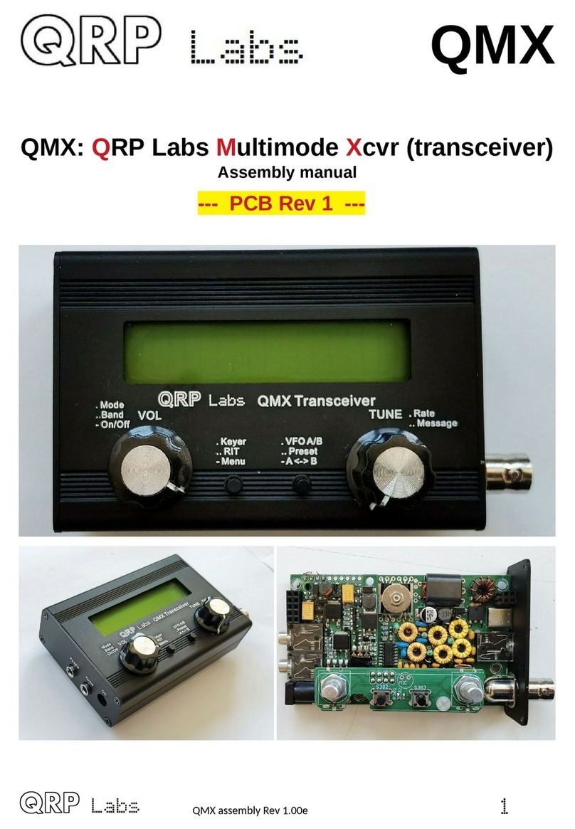
QRP Labs QMX User manual

QMX
QMX: QRP Labs Multimode Xcvr (transceiver)
Operating manual, firmware .00_0 2, 05-Dec-2023
QMX operang manual; rmware 1_00_012 1

Contents
1. Overview of features...................................................................................................................................................4
2. Conne tors..................................................................................................................................................................7
3. Display elements.......................................................................................................................................................10
4. Operator Controls.....................................................................................................................................................11
4.1 Tune rate.............................................................................................................................................................12
4.2 Keyer speed.........................................................................................................................................................12
4.3 RIT........................................................................................................................................................................13
4.4 VFO mode............................................................................................................................................................13
4.5 VFO A/B operaons.............................................................................................................................................14
4.6 Frequen y Presets...............................................................................................................................................14
4.7 Automated message transmission mode............................................................................................................14
5. Menu System.............................................................................................................................................................15
5.1 Saving urrent operang parameters (VFO frequen y et ).................................................................................16
5.2 Types of onguraon menu item.......................................................................................................................16
5.3 Eding a onguraon menu parameter.............................................................................................................16
5.4 Eding a LIST parameter......................................................................................................................................17
5.5 Eding a BOOLEAN parameter............................................................................................................................17
5.6 Eding a NUMBER parameter..............................................................................................................................17
5.7 Eding a TEXT parameter....................................................................................................................................18
5.8 Audio menu.........................................................................................................................................................19
5.9 Frequen y presets menu.....................................................................................................................................20
5.10 Messages menu.................................................................................................................................................20
5.11 Keyer menu.......................................................................................................................................................21
5.12 CW De oder menu.............................................................................................................................................25
5.13 Digi interfa e.....................................................................................................................................................27
5.14 Bea on menu.....................................................................................................................................................29
5.15 Display/ ontrols menu.......................................................................................................................................36
5.16 Prote on menu................................................................................................................................................40
5.17 System ong....................................................................................................................................................41
5.18 Hardware tests..................................................................................................................................................46
5.19 Fa tory Reset.....................................................................................................................................................47
5.20 Update rmware...............................................................................................................................................48
6. Operang QMX on digital modes..............................................................................................................................49
7. Firmware Update pro edure.....................................................................................................................................56
8. Terminal Appli aons................................................................................................................................................60
8.1 PC terminal emulator..........................................................................................................................................60
8.2 Entering terminal appli aons mode..................................................................................................................61
8.3 Exing terminal appli aons mode....................................................................................................................61
8.4 Conguraon menu.............................................................................................................................................62
8.5 Band onguraon.............................................................................................................................................63
8.6 Hardware tests menu.........................................................................................................................................65
8.6.1 Audio lter sweep............................................................................................................................................66
8.6.2 RF lter sweep.................................................................................................................................................67
8.6.3 Image sweep....................................................................................................................................................69
8.6.4 SWR sweep......................................................................................................................................................71
8.6.5 Diagnos s........................................................................................................................................................71
8.6.6 GPS viewer.......................................................................................................................................................74
QMX operang manual; rmware 1_00_012 2
8.7 PC and CAT menu...............................................................................................................................................76
8.7.1 System ong...................................................................................................................................................77
8.7.2 Input Analysis.................................................................................................................................................. 77
8.7.3 CAT ommand test...........................................................................................................................................81
8.7.4 CAT monitor.....................................................................................................................................................86
8.7.5 Log le.............................................................................................................................................................86
8.8 System menu......................................................................................................................................................89
8.9 Exit terminal........................................................................................................................................................89
9. Resour es..................................................................................................................................................................90
10. Do ument Revision History.....................................................................................................................................90
QMX operang manual; rmware 1_00_012 3

. Overview of features
QMX is a high performance, five-band multi-mode 5W QRP transceiver kit, which implements a
sophisticated DR receiver in a 168MHz 32-bit ARM Cortex M4 microcontroller ( TM32F446).
Most of the features are implemented digitally in firmware, and the feature set is continuing to be
expanded by ongoing firmware development. Please refer to the later section on planned future
functionality. This section provides a brief summary of the features to explore and enjoy.
QMX is highly portable
The small size and very low receive current consumption (as low as 80mA) are key features of
QMX, making it an ideal transceiver for portable operations including OTA and POTA activations.
QMX is a standalone CW transceiver, or a Digimodes modem
You can use QMX on its own, plugging in earphones, power supply, paddle and antenna and
operating CW; or, you can connect it to a PC with a single U B-C cable, to provide CAT control
and Digital audio to the PC and use it with W JT-X or other programs for single-tone F K digital
modes (not suitable for P K31 and phase shift modes until B is implemented).
Synthesised VFO with rotary encoder tuning
The VFO is an i5351A or M 5351M synthesiser chip, configured by the microcontroller. A rotary
encoder tunes the VFO, with a variable tuning rate. The radio includes two VFOs, A and B. You
can swap from one to the other, copy the contents of the active VFO to the inactive one, or
operate plit (Transmit on VFO A, receive on VFO B). There is also a RIT mode offering a receive
offset of up to +/- 9,999Hz. The CW offset is also adjustable, and CW-R (sideband swap) mode is
supported.
Memory features
There are 16 frequency presets for your favourite operating frequencies. Each frequency preset
can be edited in the configuration menu, or loaded/saved into/from the currently operating VFO.
Message mode
The firmware supports storage of 12 messages. Each of these are 50 characters long. A single
button click shows the list of messages to send. Message sending can be configured to send just
once, or a configurable number of times, or indefinitely repeating. The interval between
transmissions is also configurable. The message feature can be useful, for example, for setting up
a repeated CQ call with a pause between repeats, during which you can listen for any answers. As
soon as you touch the key the message sending is canceled. When message sending is in
progress an ‘M’ character appears near the top right of the display.
CW Keyer
Operation with a traight key is possible, but the firmware also includes an Iambic keyer, for
connection of a paddle. The keyer can be configured to operate in Iambic modes A or B, or
Ultimatic mode. The keyer speed is variable via a single button press during operation.
Full or semi break-in
With its solid-state, microcontroller operated transmit/receive switch, the radio can operate cleanly
in full break-in “Q K” mode, or if you prefer, semi-break in.
QMX operang manual; rmware 1_00_012 4

CW Decoder
A CW decoder operates in the microcontroller. This can be useful on air, particularly for
newcomers to CW, though it is never anywhere near as good in QRM or weak signal conditions as
a good CW operator using the wet-ware between his ears. The decoder has a “Practice” mode
too, for you to practice your CW sending without actually generating RF. The decoder can also be
used to conveniently enter text in the message storage, or for configuration of any of the other
menu items. The decoder can also be switched off if desired.
CW, FSKCW or WSPR Beacon mode
A beacon is included too, and this can be configured to operate in CW, F KCW or W PR mode.
Owners of the QRP Labs Ultimate-series weak signal mode transmitter kits will be familiar with the
operation of W PR. A GP module such as the QRP Labs QLG2 GP receiver kit can optionally
be connected to this CW transceiver kit to provide frequency and time discipline, as well as setting
the Maidenhead locator (from latitude and longitude) that is encoded in the W PR message.
S-meter and Battery voltage
An -meter and battery voltage indicator can be enabled for display on the LCD. These are both
configurable to your needs. The battery voltage indicator would be useful if you intend to operate
the radio portable on battery power. Battery voltage range warning can be configured and
prevention of transmit if out of range.
SWR measurement
Built-in WR bridge always in-line, continuously measures WR and power output; these can be
configured to show on the display, and a configurable bad- WR threshold to prevent transmit is
available.
Real time clock
A real-time clock can be displayed at the bottom right of the LCD. The time can be set by
connecting a GP receiver such as the QRP Labs QLG2 temporarily to the QMX. When power is
disconnected from the QMX, the time is lost and will start at 00:00 at next power-up.
Built-in high performance 48ksps 24-bit USB soundcard
No more audio hum ground loops, or lossy noisy connections; a simple U B cable connection to
the PC is all that is required for perfect lossless noise-free, hum-free audio transfer back and forth
between QMX and the PC.
CAT control - PC Control commands
The same U B connection also implements a Virtual COM serial port for CAT control commands.
This implements a subset of the Kenwood T -480 command set, with one or two minor additions
and exceptions.
It is intended to allow easy operation of the QMX in conjunction with logging software, which
typically queries the transceiver to determine operating frequency and other operating parameters.
The CAT control interface also supports some basic control features for remote control of QMX if
required, and is used by software such as WXJT-X when in digital mode, to control the operating
frequency and manage transmit/receive switching.
Rich terminal interface
The Virtual COM serial port connection can be used with a Terminal emulator such as PuTTY, to
access a range of configuration, alignment and debug tools within QMX, all delivered over the
QMX operang manual; rmware 1_00_012 5

serial terminal interface. There are additional serial ports which may be enabled at a later time
(firmware enhancement). The complete configuration menu is from the terminal too. Alignment
tools include an RF sweep tool which uses the QMX’ own internal signal generator injected into
the RF port, to sweep across the band pass filters so you can check whether the performance is
optimal and make adjustments if desired.
GPS Interface
The QMX kit has a GP interface, which is used for calibration, setting the real time clock, and for
frequency and time discipline and locator setting during W PR operation. The GP interface
(1pps and 9600 baud serial data) shares the same pins as the paddle dit and dah signals
(necessary due to limited processor I/O). The style of this interface is the same as the earlier
QCX-series CW transceiver kits.
The GP should only be connected during calibration functions or when the beacon is enabled.
Connection at other times puts the radio into practice mode (no RF emitted) to protect the PA. You
may temporarily connect the GP while in ordinary operation mode, for the purposes of setting the
real time clock.
QRP Labs Firmware Update
A special feature of QRP Labs kits based on TM32-series microcontrollers is the QRP Labs
Firmware Update procedure (QFU). In firmware update mode, the radio appears to a U B-
connected PC as a U B Flash drive. Updating the firmware is a simple matter of downloading the
new firmware file, unzipping it, and copying it into QMX. Firmware updates will always be free.
They will deliver performance and functionality enhancements and bug fixes.
ASSEMBLY
Assembly of the transceiver is covered in a separate document.
Note: QMX PCB Rev 2 should be used with firmware _00_0 and above.
This document describes operation of QMX, and applies to the firmware version specified. This
manual will get you started with QMX, either as a standalone CW transceiver or with your W JT-X
or other digi modes software in minutes.
PLEASE READ THE BASIC ASSEMBLY AND USE INSTRUCTIONS IN
THIS MANUAL VERY CAREFULLY BEFORE APPLYING POWER TO
THE BOARD!
QMX operang manual; rmware 1_00_012 6

2. Connectors
This is the QMX left panel.
Paddle connector
The paddle connector is a 3.5mm stereo jack socket and actually has THREE purposes:
1) Paddle for CW operation
Don’t worry if your paddle has a reversed pinout, or if you connect the dit and dah to a 3.5mm jack
plug incorrectly: there is a configuration item in the configuration menu (CW Keyer menu) allowing
you to swap the dit and dah in the firmware.
2) GP interface
Here the 1pps signal from the GP must be connected to the 3.5mm jack “tip” connection, and the
serial data (9600 baud) to the “ring” connection. In QMX these signals are 3.3V logic level;
however they are connected to 5V-tolerant I/O pins on the microcontroller so 5V logic level will
also work fine. If you are using a GP module directly, and it has the common 2.8V output logic,
this will also work fine.
QMX operang manual; rmware 1_00_012 7

Note that the QMX cannot supply +5V to the GP module power supply, and in this regard the
GP interface differs from that of the QRP Labs QCX-series transceivers. o you need to arrange
a separate 5V power supply for the QLG2 GP (for example).
3). Microphone interface
In B mode, an electret microphone and PTT switch may be connected to the Paddle port.
An internal +2.2K pullup to +3.3V is provided to power electret microphones.
Audio connector
The audio output connector is a standard 3.5mm stereo jack socket for connecting 32-ohm
earphones or similar. It is not suitable for driving a loudspeaker directly. QMX internally controls
the Left and Right channels separately which makes future interesting functionality possible.
DC connector
The DC connector is a 2.1mm barrel jack connector, the same as used on other QRP Labs
transceiver kits such as QCX+, QCX-mini and QDX.
The center pin is positive, the barrel is ground.
The supply voltage range for QMX is 6.0 to 12.0V. Maximum power output depends on the supply
voltage.
This is the QMX right panel.
QMX operang manual; rmware 1_00_012 8

RF connector
The RF connector is a 50-ohm BNC connector securely bolted to the enclosure. QMX should be
used with reasonably well-matched 50-ohm loads. Note that the WR bridge inside QMX means
that there is a DC connection to ground; if you measure using a DVM continuity or ohm-meter
between the center pin and ground, you will measure zero ohms. This also means that no
additional bleeder resistors are required across a connected resistor, to bleed away static charge
buildup.
PTT connector
The PTT connector is a 3.5mm stereo jack socket.
There are separate active grounded and active +5V outputs. The conventional way to control
external amplifiers is with a grounded PTT. However the QRP Labs 50W PA kit requires a +5V
active (Transmit) PTT control signal. o this PTT output connector is capable of providing both
styles of PTT connection.
The two outputs can be configured individually per band, in the Band Configuration menu.
Additionally they may be configured to also be active during receive – which may be used to
control some external switching for example.
Note that the two outputs have 220-ohm resistors in series, to protect internal QMX circuits in the
case of short-circuits.
USB connector
The U B connector is a U B-C type connector. When connected to a host PC, QMX appears as
both a U B sound card (24-bit 110dB 48ksps) and a Virtual COM erial port used for CAT control
and accessing the terminal applications. It therefore effectively emulates a U B hub, with two
devices connected (U B sound card, and erial).
Additionally the U B connection is used during bootloader mode, when the QMX appears for
firmware update purposes as a U B Flash drive (see later section on firmware update).
QMX operang manual; rmware 1_00_012 9

3. Display elements
The kit uses a 2 row, 16 character LCD module, with black text on a yellow/green background.
There is a backlight which can be switched off if desired, to save a few mA of current
consumption. The display has a large, easy to read font, and is perfectly readable in bright sunlight
with no backlight.
The main display layout during ordinary operation (which will be called “main operating mode”) is
shown in the following photograph. The display during beacon or message transmission modes,
menu editing, alignment etc. differs. The main display elements are as follows:
The receive VFO frequency is always displayed, to 10Hz resolution, at the top left. This
may be VFO A or VFO B. In CW mode the nominally 700Hz CW offset is automatically
applied. Ordinarily in CW mode, the displayed frequency is also used for transmission.
Tuning rate cursor: the underline appears under the digit which is currently tuned by the
rotary encoder. In this example, the tuning rate is 100Hz per click, because the cursor is
under the 100Hz digit.
Practice mode: when in CW practice mode (actual transmitting disabled), a ‘P’ is displayed
to the right of the frequency on the top row. If the practice mode was caused automatically
as a self-protection, by plugging in the GP , a ‘G’ is displayed. During saved message
transmissions, this character is set to ‘M’ and in ordinary operation, it is blank.
Mode indicator: this single character indicates the current operating mode of the tranceiver;
in the example in this photograph it is “CW”.
-meter: these 3 characters are configurable and display the -meter/ WR/Power meter.
Battery voltage: a battery icon appears to indicate the battery voltage in 7 user-definable
steps: from full to empty and 5 steps in between. It may also be shown or hidden.
Transmit VFO: in PLIT mode, the transmit VFO is displayed on the bottom row of the
display.
RIT (Receiver Incremental Tuning): when not in PLIT mode, and when the RIT is non-
zero, the RIT value is displayed in the bottom left (where the photo shows the VFO B
frequency). When RIT is non-zero, and when not in PLIT mode, the reception frequency is
the transmit VFO frequency (which may be VFO A or B) plus the RIT (which may be a
negative offset).
QMX operang manual; rmware 1_00_012 10

Decoded CW: The remaining space on the bottom row is used for displaying the decoded
CW text. When RIT is zero, and you are not operating PLIT or displaying the realtime
clock, the whole 16 characters of the bottom row are used for the CW decoder display.
When adjusting RIT or keyer speed, only the right section of the screen is used for decoded
CW. The CW decoder may be disabled in the Decoder configuration menu.
Real time clock: This can be enabled or disabled, and if enabled, is shown at the bottom
right in HH:MM format; it can be set manually or via GP serial data stream parsing (UT).
4. Operator Controls
This diagram shows the operating controls of the QMX. There are two rotary encoders at left and
right, and two push-buttons in the center. The main function of the left rotary encoder is Volume
adjustment, and that of the right rotary encoder is Tuning. However, all of the controls have
multiple functions, depending on the operating mode, menu editing, etc. The rotary encoders both
have a button on their shaft activated by pressing the knobs, and these buttons also have multiple
functions.
Most importantly: Press the left knob (VOL) with a single firm long press, to turn on or off
the radio!
The two central buttons are used during menu editing primarily for “ elect” and “Exit” functions
and may be referred to in this manual, as the “select” and “exit” buttons. elect edits a menu item
or steps down into a sub-menu; Exit saves an edited menu item or backs up to the parent menu.
QMX operang manual; rmware 1_00_012 11

It is well worth remembering while you are familiarizing yourself with the operation of the radio,
that if you get into any unexpected function or menu – you can nearly always press the “Exit”
button to cancel and get back to the main operation mode.
Each of the buttons may be pressed once, pressed twice (a double-click) or pressed for a
long-hold. This facilitates three different functions for each button.
The laser-etched captions on the QMX front panel act as a reminder of the main functions
of the various buttons and controls.
4. Tune rate
The right-hand rotary encoder tunes the active VFO. The rate of tuning is indicated by the
underline cursor. In the example below, the underline cursor is under 100Hz digits. This means the
tuning rate is 100Hz. If the cursor was under the comma , this would mean a tune rate of 500 Hz.
The available VFO tuning rates are 1kHz, 500Hz, 100Hz or 10Hz.
A press of the “Rotary” button (in the rotary encoder shaft) causes the tuning rate to change, in the
cycle 1kHz -> 500Hz -> 100Hz -> 10Hz -> 1kHz etc.
You can also press-and-hold the rotary encoder shaft button, then turn the rotary encoder
to move the cursor to the left or right; this allows selection of steps up to MHz; turn the
rotary encoder within 0.3 seconds of the button press.
4.2 Keyer speed
During operation of the radio, the keyer speed can be easily adjusted. Click the “ elect” button
once (also indicated by the text “. Keyer” on the enclosure, and the speed will be displayed on the
screen:
A14,006,50
Speed 12
Now you can adjust the speed using the rotary encoder. Press any button to return to the main
operating mode. You may operate the radio while the peed setting is shown. You can also press
the rotary encoder shaft button to select sending a stored message, while the peed adjustment
setting is active.
etting speed to 0 enables “ traight” Key mode regardless of the keyer mode setting; this is useful
for quickly being able to key down for antenna tuning purposes. It is much easier than going into
the Keyer menu, selecting straight key mode, doing the tune up, then going back into the menu to
change to Iambic again. The normal configured keyer mode is automatically restored when you
increase the speed above zero.
QMX operang manual; rmware 1_00_012 12

4.3 RIT
RIT (Receiver Incremental Tuning) allows the receive frequency to be adjusted while the transmit
frequency (the displayed VFO frequency) remains the same. It is useful if the other station is off-
tune, or drifting; other uses include working DX stations who may be listening on a different
frequency some kHz away from their transmit frequency.
This radio transceiver allows RIT values from -9,999Hz to +9,999Hz.
RIT can be easily adjusted during ordinary operation by double-clicking the “ elect” button
(indicated on the enclosure as “.. RIT”:
Now use the rotary encoder to tune the RIT. As you do so, you will hear the RIT immediately
applied to the VFO.
The tune rate of the RIT control is again indicated by the underlined digit (here 100Hz). In order to
change the tune rate, press and hold the “Rotary” button (in the rotary encoder shaft) and turn the
rotary encoder at the same time. You will see the cursor move to the left or right 1 digit at a time.
Again, the cursor under the comma indicates 500Hz tuning steps.
To cancel RIT tuning (reset the RIT to zero), press the “Exit” button; this returns to main operating
mode and sets the RIT to zero.
To return to the main operating mode, press the “ elect” button. Now the RIT is displayed under
the VFO, for example:
A14,006,50
+0,300
Remember that cancelling RIT mode is easy, just double-click the “ elect” button to show the RIT
editing, then press the “Exit” button to cancel it (which means, set it to zero).
Transmitting is possible while the RIT display is active. You can also press the rotary encoder
shaft button to select sending a stored message, while the peed adjustment setting is active.
4.4 VFO mode
A single press on the “Exit” button changes the active VFO mode. There are two independent
VFOs named A and B. There are three VFO modes for using these VFOs:
VFO A is active as transmit and receive VFO; if non-zero, RIT is applied during receive
VFO B is active as transmit and receive VFO; if non-zero, RIT is applied during receive
plit: VFO A is used for receive, VFO B is used for transmit; RIT is ignored completely
plit mode is often used by DX stations, they transmit and receive on separate frequencies.
QMX operang manual; rmware 1_00_012 13

4.5 VFO A/B operations
Frequency swap: the contents (frequency) of VFO A and B can be swapped by a single long key-
press to the “Exit” button. This can be useful when setting up the VFO frequencies.
Copy VFO A to B: To copy VFO A to B, press the “Exit” button with a long key-press then a single
short press. It is similar to tapping a CW ‘N’ slowly on the “Exit” button.
Copy VFO B to A: To copy VFO A to B, press the “Exit” button with a long key-press then a quick
double-press. It is similar to tapping a CW ‘D’ on the “Exit” button.
4.6 Frequency Presets
There are 16 frequency presets which may be used for storing your favourite frequencies, or for
just temporary use, or however you wish!
The presets are labelled 1 to 16, and can be individually edited in the Preset menu (see later).
Often it is more convenient to just save them from the current VFO frequency.
To show the list of preset frequencies in normal operation mode, double click the “Exit” button. The
display now shows something like this:
A14,027,50
S 1 14,060,00 L
The top row of the display shows the currently active VFO frequency as usual.
The bottom row shows a “1” in the 4th character, this is the number of the preset displayed. The
next number (here 14,060,00) is the frequency stored in Preset 1.
Use the rotary encoder to scroll through the list of presets until you find the one you want. Once
you have selected the desired preset, press one of the buttons to ave, Cancel or Load the
preset, as follows:
AVE the current VFO to the selected preset, by pressing the “ elect” button
CANCEL the preset operation (back to main operating mode), by pressing right rotary
encoder button
LOAD the selected preset frequency into the current VFO, by pressing the “Exit” button
The “ ” in the first character and “L” in the 16th character at the far right, are intended as a
reminder of which of the center two buttons to press to ave and to Load.
4.7 Automated message transmission mode
My favourite use of the automated message transmission mode is to send a CQ call repeatedly. If
a station answers, you can tap the key to cancel the message sending mode, then transmit.
There are 12 message memories. Each one is 50 characters long.
In order to send a pre-saved message, press the TUNE knob with a single long press. The first of
the saved messages is shown on the screen, for example if a CQ call is stored in Message 1, you
may have something like this:
QMX operang manual; rmware 1_00_012 14

A14,012,00
1. CQ CQ CQ DE G
The bottom row shows the message number at the far left (here it is message 1) followed by the
first part of the stored message. If it is blank, that means of course that you have not stored any
messages yet!
You can now use the TUNE knob to scroll back and forth between the 12 stored messages and
find the one which you want to transmit.
The message can be transmitted multiple times according to the “Repeats” parameter in the
Messages menu (see later description). The interval between the repeated transmissions is also
defined in the Messages menu, in the “Interval” parameter.
Once you have selected the message that you want to transmit, press one of the three buttons as
follows:
REPEAT: Transmit the message repeatedly by pressing the “ elect” button
ONCE: Transmit the message only once by pressing the “TUNE” knob button
CANCEL: Cancel the messages operation by pressing the “Exit” button
When REPEAT message transmission mode is activated, the number of repeats and the interval
between repeats is as specified by the Repeats and Interval parameters in the Messages menu.
The stored message transmission is sent at the currently defined keyer speed.
During the actual stored message transmission, you can immediately cancel the transmission at
any time by pressing the “Exit” button or by keying the transmitter with the Morse key or paddle if
you are using one.
While the RIT or peed adjustment modes are active, you may still operate the radio (key the
transmitter) and may also press the rotary encoder center shaft button to initiate stored message
sending.
5. Menu System
There is an extensive nested menu system with all configuration or operating parameters for the
transceiver stored in non-volatile memory (EEPROM). These are editable to control every aspect
of the radio’s behaviour. The menus are organised into groups as follows:
Audio
Presets
Messages
CW Keyer
CW Decoder
Digi interface
Beacon
Display/Controls
Protection
ystem config
Hardware tests
Factory reset
Update firmware
QMX operang manual; rmware 1_00_012 15

To enter the menu system, give a single long press to the “ elect” button. Use the TUNE knob to
scroll back and forth between the sub menu groups listed. To enter one of them, press the “ elect”
button. To return to the main operating mode, press the “Exit” button.
The golden rule while in the menu system, is to press the “ elect” button to go in to a deeper
menu level or edit an item, and the “Exit” button to back up.
In order to edit a menu item, navigate to the menu item then press the “ elect” button to start
editing. When you have finished editing the item, press the “Exit” button to save it.
NOTE that changes to configuration parameters in most cases only take effect on the radio, when
you leave the menu system and return to the main operating mode. During viewing or editing of
menu items, the radio remains in receive mode on the currently selected VFO frequency.
5. Saving current operating parameters (VFO frequency etc)
When you power down QMX by pressing the VOL knob, the display will show “ hut down” briefly
before powering down QMX. At this time, various important operating conditions of the transceiver
are stored in non-volatile storage (EEPROM) that is retained while the power is off. Next time you
switch on QMX, it will power up in the same state that you left it!
The list of items saved is:
Mode (CW, Digi etc)
VFO Mode (A, B, plit)
VFO A frequency
VFO B frequency
Tune rate
RIT
RIT tune rate
Volume level (audio gain)
Keyer speed
5.2 Types of configuration menu item
There are five types of menu configuration item, and editing these is a little different depending on
the type.
1) LI T: a fixed list of values applicable to that menu item, for example Keyer mode; certain
boolean parameters are also equivalent to a list containing only two items (ON/OFF,
DI ABLE/ENABLE, NO/YE ).
2) NUMBER: a numeric parameter such as a stored frequency preset
3) TEXT: a text configuration item such as a stored message
5.3 Editing a configuration menu parameter
To start editing a parameter, navigate to the desired parameter in the appropriate menu, and then
press the “ elect” button. When editing is active, you will see a cursor appear under the digit being
edited.
QMX operang manual; rmware 1_00_012 16

For example, here is the message repeat interval setting, containing a small number (1 or 2 digits):
The underline cursor below the 4 indicates that editing is active; turning the TUNE knob will
change the parameter value.
When you are finished editing, press the “Exit” button to conclude editing. This saves the
parameter in the microcontroller’s EEPROM memory.
A flashing inverted cursor is also available, you can choose that in the “Cursor tyle” parameter in
the “Other” menu (see later section).
The procedure for editing list, string and number parameters is described below; the above simple
example is a short number that is simply adjusted using the TUNE knob; for longer numbers such
as frequency, the procedure is different (see following sections).
5.4 Editing a LIST parameter
Editing a list parameter is very simple, it is just a matter of turning the rotary encoder. The display
scrolls through the list items. For example, this is the “Keyer mode” parameter in the “CW Keyer”
menu:
Note that the editing indicator cursor appears under the leftmost character. Turn the TUNE knob to
scroll through the list of possible values.
When you are happy with your selection, press either “ elect” or “Exit”, to save the change.
5.5 Editing a BOOLEAN parameter
Editing a BOOLEAN parameter (such as YE /NO, ENABLED/DI ABLED, ON/OFF) is exactly the
same as editing a LI T parameter, except that now the list of items is always restricted to just the
two values (representing True/False).
5.6 Editing a NUMBER parameter
When editing a number parameter, the cursor underline appears under the currently edited digit.
The cursor starts at the far left (most significant digit). The TUNE knob adjusts the selected digit.
The operation is very similar to tuning a VFO in ordinary operation.
QMX operang manual; rmware 1_00_012 17

This example shows editing the beacon frequency, in the beacon menu:
To alter the “tuning rate”, you can either
a) Press the “ elect” button to move the cursor to the next digit to the right OR
b) Turning the VOL knob allows you to move the cursor left or right.
Editing of the number is concluded, and the number is stored to EEPROM, when either:
a) You press the “Exit” button OR
b) You press the “ elect” button so many times that the cursor falls off the right hand side
Yet another way to input numbers, which is a REALLY convenient way, is to use the Morse key
and CW decoder! During editing of numeric parameters, the CW decoder is activated but only
decodes number characters 0-9. The CW decoder expects well-timed CW, with correct spacing
between words and characters. The CW decoder expects you to key in the numbers at near to the
configured Keyer speed. If you start keying in straight mode at a much different speed, the CW
decoder will adapt to your keying but this may take several characters to “sense” your keying
speed, so some characters can be missed. This is not a problem in Iambic keyer (paddle) modes.
When you have keyed in the whole number, the number is automatically saved to EEPROM,
which leaves editing mode. Once you are used to editing numeric parameters by keying in CW, it
becomes the easiest and fastest way to edit menu parameters.
5.7 Editing a TEXT parameter
An example of a text parameter you may wish to edit is the stored messages. For example, stored
message 2 is edited in the Messages menu:
Message 2
CQ CQ CQ DE G0UP
By far the easiest way to edit TEXT parameters is simply to use the CW decoder! As before, it
expects well-timed CW, with correct spacing between words and characters when using stright
key, and the CW decoder expects you to key in the characters at near to the configured Keyer
speed. If you start keying with a straight key at a much different speed, the CW decoder will adapt
to your keying but this may take several characters to “sense” your keying speed, so some
characters can be missed. The problem does not occur with Iambic (paddle) keying modes.
Editing of the parameter is concluded either when you press the “Exit” button, or when no more
characters are available for editing; for example, if you filled up the chosen Message memory.
It is also possible to edit a text parameter entirely with the buttons and rotary encoder, though this
is usually a slower way to edit text parameters. Owners of the QRP Labs Ultimate3 (or earlier)
QR /W PR transmitter kits will already be familiar with this style of editing text.
QMX operang manual; rmware 1_00_012 18

The text parameter supports all of the characters which the Message keyer can encode, which is
the same as the CW decoder can decode. pecifically, A to Z, 0 to 9, pace, then punctuation
characters / = ? . , Note = is the break character, CW -...- (dah dit dit dit dah).
The following characters/symbols have special functions.
Insert: Use this symbol to insert a character in the text. Find this character using the rotary
encoder, then press the “ elect” button to activate it. All the characters to the right of the
cursor position are shifted right one position, including the character which was originally in
the current position.
Backspace (delete): If you select this character as the current character using the rotary
encoder, then when you press the “ elect” button, the current character is deleted and the
cursor moves back left one position.
Delete all: If selected as the current character, pressing the “ elect” button has the effect of
deleting the entire message, starting again at the left of the screen. There is no “undo”, so
use with caution!
Enter Right (finished): The behaviour of this symbol is the same as Enter, except that it
preserves all the text, including the text to the right of the cursor. It simply saves the whole
line.
Enter (finished): If selected as the current character using the rotary encoder, pressing the
“ elect” button is used to finish editing the setting. The setting is saved, and you leave
editing mode. Note that the text that is saved is only the text to the left of the Enter symbol. If
you select this symbol and press the “ elect” button when you are not at the furthest right
position of the message, then everything right of your position is deleted.
You can also move the cursor backwards and forwards within the text being edited, by turning the
VOL knob. This moves the cursor position within the text parameter.
5.8 Audio menu
olume step
0.5dB
Each click of the main volume control knob increases or decreases the receiver volume by this
step. Available values are 0.25dB, 0.5dB, 1dB, 2dB and 4dB.
Sidetone volume
59
ets the sidetone volume. When editing the menu on the QMX itself, you are able to close the key
contacts (dit or dah) normally but no RF transmission will occur. You can use this feature to check
how the sidetone sounds and select a comfortable volume.
QMX operang manual; rmware 1_00_012 19

Sidetone abs/rel
Relative
This setting determines how the idetone volume setting is applied. There are two possible values
as follows:
•Relative: the sidetone level is set by the “ idetone volume” parameter, however it is also
affected by the main volume control. As you increase the volume for example, by turning
the volume control clockwise, the received signals AND the sidetone volume both increase
by the same amount.
•Absolute: the sidetone level is fixed by the “ idetone volume” parameter, regardless of the
setting of the main volume control. If you adjust the main volume, it only changes the sound
level of the received signals, the sidetone level remains the same.
5.9 Frequency presets menu
There are 16 frequency presets, labelled 1 to 16. This example shows Preset 5:
Preset 5
14,020,000
All of the Preset menu items are NUMBER types. Refer to the “Editing a NUMBER parameter”
section above for instructions on how to edit a NUMBER parameter.
It is also convenient to load the current VFO into the preset memories as described in the section
above titled “Frequency Presets”.
5. 0 Messages menu
There are 14 configuration items in the Messages menu. The first 12 are the stored messages,
each of which is up to 50 characters long. These are followed by the Interval and Repeats
parameters.
The stored message presets are 50 characters long, and edited as per the “text” editing procedure
described previously.
Message 1
Turn the TUNE knob to select the Message from 1 to 12 which you wish to edit, then press the
“ elect” button. Now you can edit the message text in one of two ways:
1) Choose each character individually from the list, using the TUNE knob to select the desired
character; when you have chosen the correct character, press the “ elect” button to move
QMX operang manual; rmware 1_00_012 20
Other manuals for QMX
1
Table of contents
Other QRP Labs Transceiver manuals

QRP Labs
QRP Labs QDX User manual

QRP Labs
QRP Labs QCX User manual

QRP Labs
QRP Labs QCX-mini CW User manual

QRP Labs
QRP Labs QDX User instructions

QRP Labs
QRP Labs QCX-mini User manual

QRP Labs
QRP Labs QCX 5W CW User manual

QRP Labs
QRP Labs QMX User manual

QRP Labs
QRP Labs QCX Operating instructions

QRP Labs
QRP Labs QDX User manual
Popular Transceiver manuals by other brands

Vertex Standard
Vertex Standard VX-160E operating manual

Standard Horizon
Standard Horizon HX210 owner's manual

Kenwood
Kenwood TM-631A instruction manual

Kenwood
Kenwood FM Transceiver TK-481 Service manual

Epiq Solutions
Epiq Solutions Sidekiq Stretch Hardware user manual

Kenwood
Kenwood TK-3107 Service manual