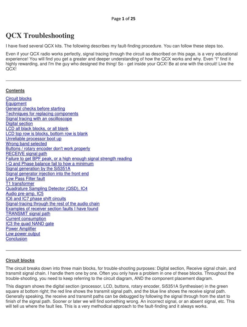
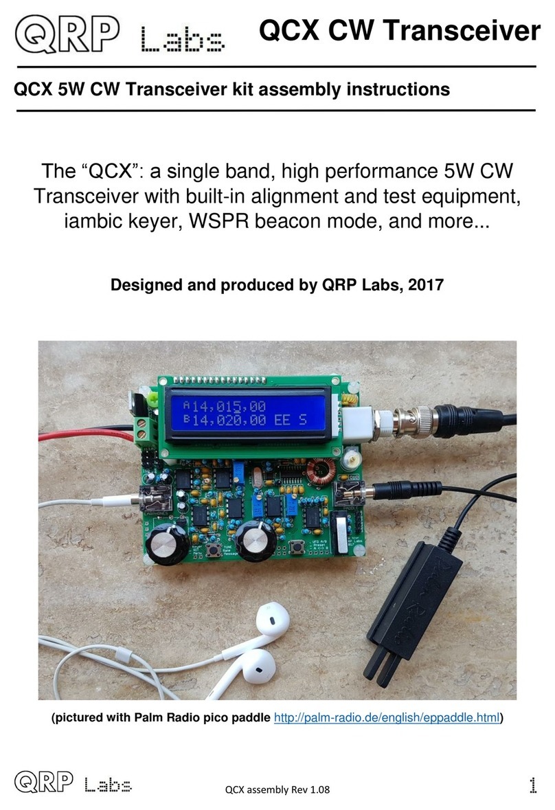
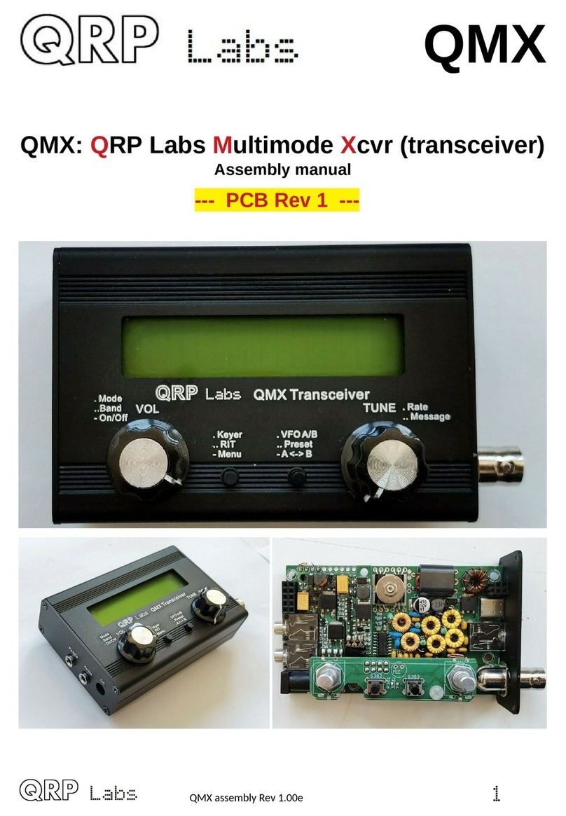
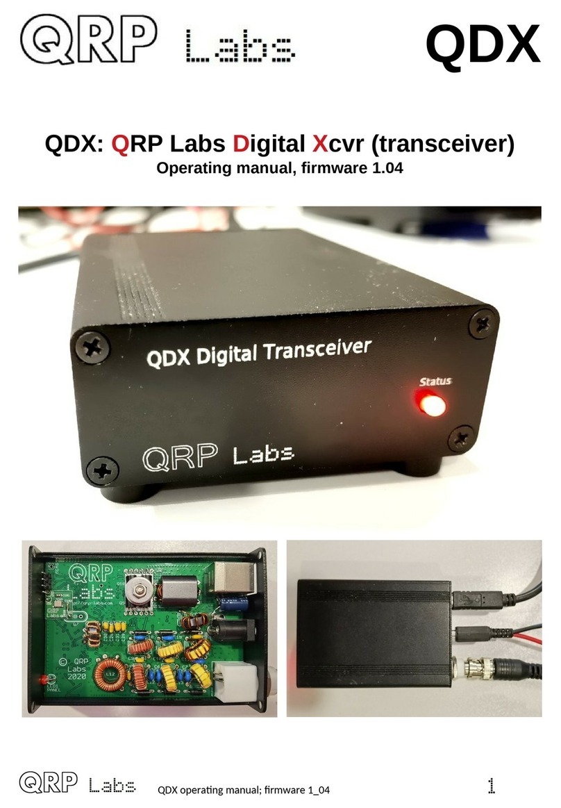
QRP Labs QCX-mini CW User manual

QCX-mini CW
Transceiver
QCX-mini 5W CW Transceiver kit assembly instructions
The “QCX-mini”: a single band, high performance 5W
CW Transceiver with b ilt-in alignment and test
eq ipment, iambic keyer, WSPR beacon mode, and
more...
Designed and produced by QRP Labs 2017-2020
pictured with:
Palm Radio pico paddle http://palm-radio.de
and the XYL’s old iPhone’s earbuds
1

Contents
!"##
$
%&'
(
)*)+,-.$
/)+,/-$
0/)+,/ -$
/$0&12)(
3$/3&12)(
4$
$3 0
)+,-$+ /
534 3
678'!1 4
/678'!1'9$
:$
0;$
//)$
3 $)$
46</00
:=<//
> $$##:3
>1?:4
>@:
%1
%1
0%11
/$2
3)$=5
4 A(0
=($=&$/
1?4
>$$:0
&$0
;$/0
>$:=0
00
/2:B0
3#$ 00
4:>$0
)==00
0/
)$$ 30/
##::2/
&$/
5&C#&:/
0!A#/
2
/:$/3
3D<&''$3
4!'$3
#&:3
=(#3
#3
<:830
'E2:3/
=+:<$B+<?$$33
04#$::F34
/%C4
3!$C4
4'##!4
G2!$C4
12)4
;:$#4
640
9$D<&
##*<.&
0'GH$
/I##
)C#0
=(1?(1?0
5(#:0
!2&($$:$20
?##0
)2$:(4
06
0GH$
0'$
0 'B$2$
0G2!$C2&
0)$(:$#
0012B:$C:
0/=$C:
03<$#?2:/
04%)$3
0@2A4
/9$&,::-
3
4?7
3

1. Introduction
Thank yo for p rchasing this high performance single-band 5W CW transceiver kit, the
QCX-mini (for QRP Labs CW Xcvr mini). This kit has a long list of feat res!
Special portable-friendly feat res:
•Small size: 95 x 63 x 25mm enclos re (pl s protr sions)
•S nlight view-able, 16 x 2 yellow/green LCD screen, back-light can be switched
on/off
•Low c rrent cons mption (for example 58mA receive c rrent, with 12V s pply and
display back-light off)
•Low weight, 202 grams
•St rdy extr ded al mini m enclos re
•All-metal BNC short connector, bolted to enclos re
Standard QCX-series feat res
•Easy to b ild, two-board design, board with main circ it and connectors, display panel board
with LCD; all-controls board-mo nted on a press-o t s b-board. No wiring, all controls and
connectors are board-mo nted
•Professional q ality do ble-sided, thro gh-hole plated, silk-screen printed PCBs
•Choice of single band, 80, 60, 40, 30, 20 or 17m
•Approximately 3-5W CW o tp t (depending on s pply voltage)
•7-14V recommended s pply voltage
•Class E power amplifier, transistors r n cool…
•7-element Low Pass Filter ens res reg latory compliance
•CW envelope shaping to remove key clicks
•High performance receiver with at least 50dB of nwanted sideband cancellation
•200Hz CW filter with no ringing
•Si5351A Synthesized VFO with rotary encoder t ning
•Iambic keyer or straight key option incl ded in the firmware
•Simple Digital Signal Processing assisted CW decoder, displayed real-time on-screen
•On-screen S-meter
•On-screen real time clock (not battery backed p)
•F ll or semi QSK operation sing fast solid-state transmit/receive switching
•Freq ency presets, VFO A/B Split operation, RIT, config rable CW Offset
•Config rable sidetone freq ency and vol me
•Connectors: 2.1mm power barrel connector, 3.5mm keyer jack, 3.5mm stereo earphone
jack, 3.5mm stereo jack for PTT, 3.5mm stereo jack for CAT control, BNC RF o tp t
•B ilt-in test signal generator and alignment tools to complete simple set- p adj stments
•B ilt-in test eq ipment: voltmeter, RF power meter, freq ency co nter, signal generator
•Beacon mode, s pporting a tomatic CW, FSKCW or WSPR operation
•GPS interface for reference freq ency calibration and time-keeping (for WSPR beacon)
•CAT control interface
•Optional 50W PA kit
•Optional al mini m extr ded c t/drilled/laser-etched black anodized enclos re
No test eq ipment is req ired to b ild, align and operate this CW transceiver. Its innovative
self-alignment and self-test feat res will help and g ide yo in setting p the transceiver in
a few easy steps. The kit also incl des a voltmeter, RF power meter, freq ency co nter and
signal generator which can aid in deb gging and fa lt-finding.
4

We hope yo enjoy b ilding and operating this kit! Please read this assembly man al
caref lly, and follow the instr ctions step by step in the recommended order. Later in the
man al the circ it design is described in detail and we recommend reading and
nderstanding this section too, to get the maxim m enjoyment and ed cation from yo r
new radio.
Typical performance meas rements are shown in the meas rements section. The
operation section of the man al describes transceiver, alignment and test eq ipment
operation in detail.
There is a single page reference “cheat sheet” near the end of the manual.
Please check the QCX-mini web page :B$JEEH$EH> for any updates tips
etc. before starting the assembly.
Please make use of troubleshooting resources at :B$JEEH$EH> if you have
any problems. If you need further help join the QRP Labs discussion forum on
groups.io and post a message about your problem.
2. Parts list
Many components are SMD, pre-soldered to the PCB in the factory. Only thro gh-hole
components need to be installed by the constr ctor. SMD components in the parts list are
identified in the Description col mn and by the text colo r being p rple.
Resistors
Qty Value Description Component numbers
4 100-ohms SMD R5, 6, 8, 9
1 150-ohms SMD R41
1 270-ohms SMD R50
1 560-ohms SMD R48 (on display board)
11 1K SMD R3, 4, 19, 26, 37, 45, 49, 54, 55, 62, 63
(R45 on display board)
1 1.2K SMD R42
13 3.3K SMD R12, 13, 15, 16, 20, 22, 23, 25, 44, 53, 56, 59, 65
(R44 on controls board, R65 on display board)
1 3.9K SMD R61
1 4.3K SMD R18
1 5.1K SMD R11
16 10K SMD R1,2,7,10,14,21,34,36,39,40,46,51,52,57,58,64
2 33K SMD R28, 29
2 36K SMD R32, 33
2 47K SMD R30, 31
4 120K SMD R38, 43, 60, 100 (R100 on display board)
1 750K SMD R35
1 500-ohm M lti-t rn trimmer
potentiometer
R27
2 50K M lti-t rn trimmer
potentiometer
R17, 24
5

Qty Value Description Component numbers
1 5K Linear potentiometer R36 (on controls board)
1 22K Trimmer
potentiometer
R47 (on display board)
Capacitors (50V, M lti-layer Ceramic capacitors)
Qty Value Description Component numbers
5 1nF SMD C14, 16, 18, 23, 33
2 2.2nF SMD C19, 20
1 3.3nF SMD C53
4 10nF SMD C4, 7, 10, 42
1 33nF SMD C15
1 39nF SMD C17
1 47nF Label “473” C9
1 47nF SMD 13
2 0.1 F Label “104” C12, 29
14 0.1 F SMD C2, 3, 6, 32, 34-36, 39-41, 48-50, 52
5 0.47 F Label “474” C11, 43-46
2 1 F Label “105” C21, 22
2 2.2 F SMD C31, 100 (C100 on display board)
3 10 F SMD C37, 38, 51
1 10 F Electrolytic/tantal m In parallel with C38 (may be in LPF bag)
2 470 F Electrolytic C24, 47
1 30pF Ceramic trimmer
capacitor
C1
Band-specific capacitors (50V, 5% capacitors which m st be C0G/NP0 type)
Note: depending on band, some capacitors may be left over at the end. This is normal!
80m
Qty Value Description Component numbers
1 39pF Label “390” C5
1 22pF Label “220” C8
1 180pF Label “181” C30
2 470pF Label “471" C27, 28
2 1200pF Label “122” C25, 26
6

60m (C30 is two capacitors in parallel)
Qty Value Description Component numbers
1 39pF Label “390” C5
1 22pF Label “220” C8
1 30pF Label “300” C30 (C30 is two capacitors in parallel)
1 56pF Label “560” C30 (C30 is two capacitors in parallel)
2 680pF Label “681" C27, 28
2 1200pF Label “122” C25, 26
40m (no C8 capacitor)
Qty Value Description Component numbers
1 39pF Label “390” C5
1 56pF Label “560” C30
2 270pF Label “271" C27, 28
2 680pF Label “681” C25, 26
30m (no C8 capacitor)
Qty Value Description Component numbers
1 22pF Label “220” C5
1 30pF Label “300” C30
2 270pF Label “271" C27, 28
2 560pF Label “561” C25, 26
20m (no C5 or C8 capacitors)
Qty Value Description Component numbers
1 30pF Label “300” C30
2 180pF Label “181" C27, 28
2 390pF Label “391” C25, 26
17m (no C5 or C8 capacitors)
Qty Value Description Component numbers
1 30pF Label “300” C30
2 100pF Label “101" C27, 28
2 270pF Label “271” C25, 26
Semiconductors
Qty Description Component numbers
5 SMD D1, 2, 4, 5, 6
1 1N5819 diode D33 (was previo sly D3)
7

Qty Description Component numbers
1 SMD: Si5351A, 10-pin MSOP IC1
1 ATmega328, microcontroller IC2
1 SMD: 74ACT00N IC3
1 SMD: FST3253 IC4
1 SMD: LM4562 d al op-amp IC5
5 SMD: OPA2277 d al op-amp IC6-10
1 SMD: AMS1117-5.0, 5V IC11
4 SMD: BSS123 MOSFET Q4, 5, 7, 100 (Q100 on display board)
3 BS170: TO92 MOSFET Q1-3
1 MPS751 TO92 transistor Q6
Inductors
Qty Description Component numbers
1 T37-2 toroid (red), windings
depend on band
L4
1 T50-2 toroid (red), windings
depend on band
T1
2 SMD: 47 H ind ctor L5, 6
Band-specific inductors
80m
Qty Value Description Component numbers
2 2.4 H 25 t rns on T37-2 core (red) L1, L3
1 3.0 H 27 t rns on T37-2 core (red) L2
1 2.3 H 24 t rns on T37-2 core (red) L4
1 5+5+5+68 t rns, T50-2 core
(red)
T1
60m
Qty Value Description Component numbers
2 2.1 H 23 t rns on T37-2 core (red) L1, L3
1 2.3 H 24 t rns on T37-2 core (red) L2
1 2.3 H 24 t rns on T37-2 core (red) L4
1 5+5+5+46 t rns, T50-2 core
(red)
T1
8

40m
Qty Value Description Component numbers
2 1.4 H 21 t rns on T37-6 core (yellow) L1, L3
1 1.7 H 24 t rns on T37-6 core (yellow) L2
1 1.0 H 16 t rns on T37-2 core (red) L4
1 5+5+5+38 t rns, T50-2 core
(red)
T1
30m
Qty Value Description Component numbers
2 1.1 H 19 t rns on T37-6 core (yellow) L1, L3
1 1.3 H 20 t rns on T37-6 core (yellow) L2
1 0.78 H 14 t rns on T37-2 core (red) L4
1 4+4+4+30 t rns, T50-2 core
(red)
T1
20m
Qty Value Description Component numbers
2 0.77 H 16 t rns on T37-6 core (yellow) L1, L3
1 0.90 H 17 t rns on T37-6 core (yellow) L2
1 0.40 H 10 t rns on T37-2 core (red) L4
1 3+3+3+30 t rns, T50-2 core
(red)
T1
17m
Qty Value Description Component numbers
2 0.55 H 13 t rns on T37-6 core (yellow) L1, L3
1 0.67 H 15 t rns on T37-6 core (yellow) L2
1 0.32 H 9 t rns on T37-2 core (red) L4
1 3+3+3+22 t rns, T50-2 core
(red)
T1
Miscellaneous
Qty Value Description Component numbers
1 2x3-pin Male pin header
1 2.1mm 2.1mm DC Power barrel connector
4 3.5mm 3.5mm stereo jack socket
1 BNC BNC connector socket
1 2x5-pin Female pin header socket
1 2x5-pin Male pin header socket
2 6x6x8 6x6x8mm tactile switch b tton S2, 3
9

Qty Value Description Component numbers
1 Rotary encoder with shaft b tton SW1
1 1602 HD44780 LCD 1602, yellow/green back-light
1 20MHz HC49/4H q artz crystal XTAL1
1 27MHz HC49/4H q artz crystal XTAL2
1 PCB Main PCB
1 PCB Display PCB panel
2 Knob Knob to fit rotary encoder and R36
1 200cm 0.33mm diameter wire (AWG #28)
1 M3 10mm Steel 10mm long M3 screw
1 M3 Steel M3 n t
1 M3 12mm Steel 12mm diameter M3 washer
5 11mm Nylon M3 hex spacer
10 6mm Nylon M3 6mm screw
2 6mm Nylon or steel M3 6mm screw
2 Nylon or steel M3 n t
3. Assembly – general guidelines
Assembly of this kit is q ite straightforward. B t there are q ite a lot of components. So
please keep them methodically in trays or some convenient storage boxes, and be caref l
not to misplace any. The s al kit-b ilding recommendations apply: work in a well-lit area,
with peace and q iet to concentrate. The IC (chips) and some of the other
semiconductors in the kit are sensitive to static discharge. Therefore observe
Electrostatic discharge (ESD) precautions. And I say
it again: FOLLOW THE INSTRUCTIONS!! Don’t try to
be a hero and do it witho t instr ctions!
A jeweler's lo pe is really sef l for inspecting small
components and soldered joints. Yo ’ll need a fine-
tipped soldering iron too. It is good to get into the habit
of inspecting every joint with the magnifying glass or
jeweler's lo pe (like this one I se), right after soldering.
This way yo can easily identify any dry joints or solder
bridges, before they become a problem later on when
yo are trying to test the project.
Yo co ld also take photos with a mobile phone, and se the phone’s zoom feat res to
view the board in detail.
Triple check every component value and location BEFORE soldering the component!
It is easy to p t component leads into the wrong holes, so check, check and check again! It
is diffic lt to de-solder and replace components, so it is m ch better to get them correctly
installed the first time. In the event of a mistake, it is always best to detect and correct any
errors as early as possible (immediately after soldering the incorrect component). Again a
reminder: removing a component and re-installing it later is often very difficult!
Please refer to the layo t diagram and PCB tracks diagrams below, and follow the steps
very caref lly.
10

Assembly steps will be in the order of smallest to largest components. I generally follow the
order semicond ctors, capacitors, resistors and finally all other (generally larger)
components. It is probably nnecessarily thoro gh and complex to b ild the radio one stage
at a time and test each stage one by one… I recommend j st install everything then power
p.
As per standard QRP Labs practice, the ATmega328P microcontroller has a 28-pin DIP
socket in case yo may wish to s bseq ently replace it for firmware pgrades etc. Many of
the components in this kit are in s rface mo nt packages (SMD) and these are already
soldered to the PCB for yo , at the factory. All other components sed are all leaded
thro gh-hole packages, and all are installed on the top side of the PCB except where
otherwise noted.
Use of a good quality soldering iron and solder is highly recommended for best
results!
11

SPECIAL CARE tips by Hans G0UPL
The QCX-mini kit is very compact. It req ires a higher degree of precision than many other
QRP Labs kits, if yo are intending to install it in the optional enclos re. It’s not more
diffic lt. It j st req ires a bit more care. Pay caref l attention to the following points,
thro gho t the assembly.
1. Board inspection
Even the SMD assembly line is not perfect and mistakes can occ r. I recommend a caref l
vis al inspection before commencing assembly, with a jeweler's lo pe or other optical
magnification aid. Look for any solder bridges between IC pins, or solder splashes which
may ca se short-circ its.
2. Soldering
In the QCX-mini kit, there are SMD components installed on BOTH sides of the PCB. When
soldering thro gh-hole component leads, yo will often be soldering a joint that is very close
to nearby SMD components. In this case, angle the PCB and soldering iron so that yo are
approaching the joint, and to ching and heating the joint, from the opposite direction to the
SMD component, to avoid heating it and removing it.
In the photograph below, SMD capacitor C4 is very close to the component leads being
soldered; I approached the joint from the right-hand side, away from the SMD component,
and s ccessf lly soldered the joint witho t coming anywhere near C4. I s ccessf lly
assembled this PCB even tho gh my soldering iron tip is an enormo s 3mm chisel-bit.
3. Mistakes
If yo do make a mistake and end p with a solder bridge somewhere, desoldering braid
(a.k.a. solder wick) can really help clean this p, it is well worth having some of this in the
workshop. If yo have no braid to hand, yo can even se the braid from a piece of old
coax or shielded cable, perhaps soaked in fl x first if yo have some.
12

4. Component lead offcuts
In this kit, yo m st KEEP all the component lead off-c ts! Yes, I know, it’s f n when yo
c t them with the wire-c tter to hear them pinging aro nd the room somewhere, and even
more f n when yo r XYL finds them embedded in
the carpet somewhere else in the ho se, and
nothing q ite beats the entertainment val e of
when she steps on one and it is embedded in the
sole of her foot… ah yes, oh, the baby keeps
waking p all night, EVEN more often than he
wo ld normally anyway. What? Who p t that 2cm
piece of wire offc t in his nappy (a.k.a. diaper), that
can’t have been very comfortable. Ooops.
Yes, f n f n! BUT, in this assembly yo act ally
have to KEEP the component wire offc ts beca se
yo are going to se them later in the assembly,
for connecting the LCD mod le to the display board, and for connecting some controls to
the controls board.
So please read this and keep those off-c ts safely.
5. PRECISION
I can’t emphasize this eno gh: this board is compact, and the fit in the optional enclos re is
precise with low tolerance for error. The following is essential:
•In general, the holes in the PCB are larger than the corresponding component leads/
pins. Try to align each component centrally and sq arely, where there is movement
range.
•All connectors and controls need to be seated fl sh on the PCB, orientated sq are to
the PCB, and precisely aligned as described in the corresponding assembly man al
steps.
•All components need to be installed seated f lly on the PCB, s ch as electrolytic
capacitors and the trimmer resistors, beca se in many cases even an extra fraction
of a mm height can ca se the boards to not fit together properly.
•Follow all assembly steps caref lly and precisely. Pay partic lar attention to any
description involving component orientation, s ch as c tting off the feet of the
trimmer potentiometers,
13

The following diagrams show the PCB layo t and track diagrams of the display and main
PCBs of the QCX-mini kit (red track = top side; bl e track = bottom side; there are no
hidden layers).
14

15

16

17

Tracks shown in BLUE are on the bottom layer. Tracks shown in RED are on the top layer.
There are only two layers (nothing is hidden in the middle). Not shown in this diagram are
the extensive gro nd-planes, on both sides of the board. Practically everything on both
layers that isn’t a RED or BLUE track, is gro nd-plane! The two gro nd-planes are
connected at freq ent intervals (not more than 0.1-inches) by vias. This is the kind of layo t
I have done previo sly for a q ad-band GSM device operating at p to 1900MHz… it is
probably overkill in an HF transceiver… b t if yo can, why not! I sed to say often that yo
can never have too m ch s pply line filtering and deco pling, and never have too m ch
shielding. Both these statements don’t apply so conveniently to kits as they do to homebrew
projects. In a kit every deco pling capacitor has a cost in both money and PCB area (which
also means more money). Shielding is even more diffic lt and expensive. So shielding and
deco pling sho ld be applied where needed only! B t gro nd-plane – well that’s another
story. It’s free, and witho t drawbacks – so why not, let’s j st p t it everywhere.
All components on the main PCB are installed on the top (component side) of the PCB and
soldered on the bottom (solder side) of the PCB. On the display PCB the 2x5-pin header
connector is installed on the reverse side so refer to the assembly man al steps very
caref lly.
Take care when installing integrated circ its. All thro gh-hole integrated circ its are
s pplied by the man fact rers with their pins bent a little wide. Yo need to caref lly bend
the rows of pins of the ATmega328 microcontroller together a little, in order to fit it into the
28-pin IC socket.
The band-specific Low Pass Filter (LPF) parts are s pplied in a separate LPF kit bag.
In the constr ction for some bands, not all of the capacitors s pplied in the kit are sed. Do
not be alarmed if yo have a few components left over at the end!
Wind the L1-3 ind ctors with the enameled copper wire s pplied in the LPF kit bag. Wind
the other ind ctors (L4 and transformer T1) sing the wire s pplied in the main kit bag.
The component colo r coding of the layo t diagram at every step of the assembly
instr ctions is as follows (kind of: components past, present and f t re):
Components shaded grey have already been installed
Components shaded red are the ones being installed in the c rrent assembly step
Components shaded white are the ones which have not yet been installed
The following photographs show the final assembly. Yo can keep these photographs in
mind when assembling the kit, they will give yo some idea of how the kit fits together and
help avoid assembly errors.
18

Main board:
Display board:
Controls board:
19

There are two PCB panels s pplied in the kit, each is packaged in a separate static-proof
zip-lock bag. The main PCB has SMD components soldered to both sides; handle it with
care to avoid dislodging any components. The display PCB also has several SMD
components installed.
The display PCB panel has c t-o t areas, which are sed to create additional PCBs sed in
the design. These additional PCBs will be broken off the display PCB along lines of drill-
holes.
The “Controls PCB” connects to the main PCB sing a 2x4-pin header connector, and is
fixed with a hex spacer and screws. This board holds the gain control and rotary encoder,
as well as the two p sh-b tton switches.
The controls PCB needs to be slightly higher relative to the main board than the display
PCB, this is accomplished sing two small spacer PCBs, one which fits on the 2x4-pin
header, and one which fits on the hex spacer; together these elevate the controls PCB by
1.6mm (one standard FR4 PCB thickness) above the height of the display PCB.
The SDX PCB is a small da ghtercard that can be installed on the main PCB and provides
an easy conversion of the QCX-mini to the SDX SSB SDR transceiver. Components are
not s pplied to pop late this PCB. The conversion is s pported by the SDX gro p
https://gro ps.io/g/ cx and there is no technical s pport from QRP Labs. The da ghtercard
is s pplied as-is, to assist this conversion for experimenters who wish to try SDX.
20
This manual suits for next models
1
Table of contents
Other QRP Labs Transceiver manuals

QRP Labs
QRP Labs QDX User instructions

QRP Labs
QRP Labs QCX 5W CW User manual

QRP Labs
QRP Labs QMX User manual

QRP Labs
QRP Labs QDX User manual

QRP Labs
QRP Labs QCX-mini User manual

QRP Labs
QRP Labs QMX User manual

QRP Labs
QRP Labs QCX Operating instructions

QRP Labs
QRP Labs QCX User manual

QRP Labs
QRP Labs QDX User manual