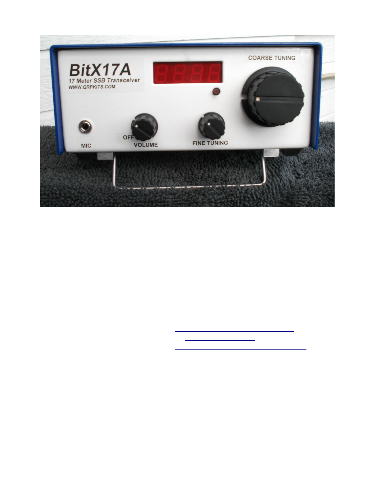
Congratulations. You have completed converting your BITX20A to a BITX17A, and are ready to
proceed with alignment of the transceiver, including transmitter driver stages and the MOSFET power
amplifiers.
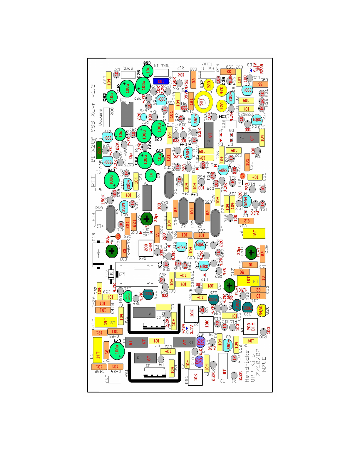
Now might be a good time to check R-2. R-8, R-83, and R-91 to insure that they are turned
totally counter-clockwise. This is to make sure that the transmitter RF drive level is at
minimum, and that the MOSFET bias levels are also at minimum. During the alignment
procedure you will set these potentiometers at their proper levels.
To proceed with transceiver alignment you will need the following tools:
●50 ohm Dummy load. This can be an actual dummy load, or a bank of non-inductive resistors
which will withstand 12 watts or more for up to one minute.
●An Oscilloscope, or Diode Voltage Probe and Voltmeter for measuring RF voltage levels at 18
MHz.
●A DC Ampere Meter capable of measuring 0 to 300 ma, and 0 to 2 amperes. There is an
alternative way to measure the 0 to 300 ma levels using voltage across a resistor. This will be
discussed in the alignment procedures.
●The Microphone that you are going to use with this transceiver, or an audio signal generator and
suitable attenuators to adjust it's output to normal microphone signal levels (nominally 40 to 50
millivolts).
●A Frequency Counter, or other means to determine VFO frequency and tuning range. A
receiver with accurate frequency readout may be suitable.
Initial Alignment Procedure:
These steps will get you on the air. A more detailed alignment method is documented in the
troubleshooting section.
1. Set the BFO and carrier oscillator frequency:
Adjust the BFO (C-72) so that when you tune across a steady carrier you can hear the zero-beat
on each side of that carrier frequency. Then adjust C-72 to a slightly lower frequency where you
can hear the upper-sideband zero-beat tone but the lower-sideband one is either gone or very
much attenuated. Now tune in an on-air SSB signal and adjust C-72 very slightly for best audio
quality.
2. Set the carrier balance:
STEP-1: With an detector probe or oscilloscope monitorin the 12.96 MHz si nal at
Page 10 of 34