2/14/2007 Page - 7
Tips and Info for First Time Builders
Installing parts:
You can insert several parts at a time onto the boar . Parts shoul be presse flush to the top of the boar . The
exception are the transistors which shoul stan off the boar by about 1/8” ue to their three legge nature. Once
you insert the part, kink one of the lea s over slightly to keep it from falling out of the boar when you flip the boar
over to sol er.
The .1 uF caps use in the kit have forme lea s, so these will not sit quite flush to the boar . Several of the isc
caps have lea spacing larger than the pa s on the boar . You can reform these lea s with your pliers so they will
sit flush to the boar .
Once you sol er a part in place, clip the lea nearly flush to the boar . Clip at the top of the little fillet of sol er
which forms aroun the lea .
Fin ing the right part.
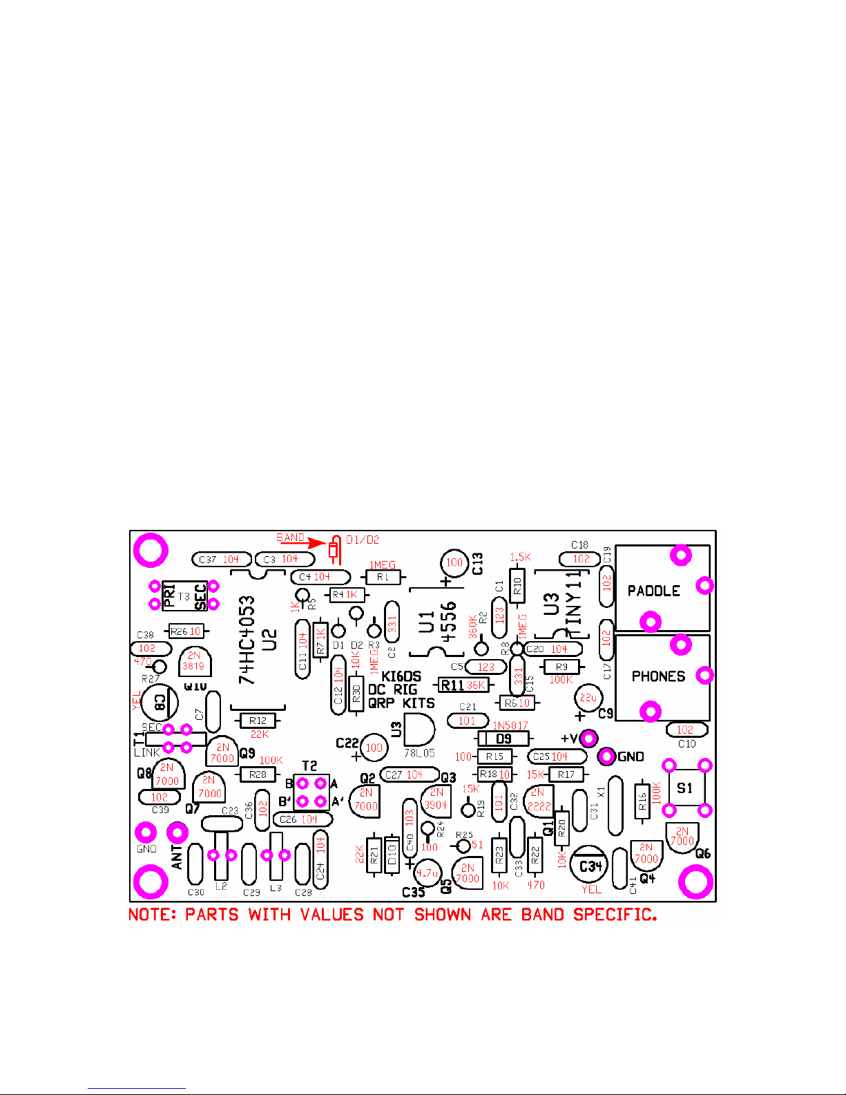
A picture at the bottom of the parts list on the previous page can be use to help i entify some of the parts. The
parts not shown shoul be obvious or e uce by the process of elimination. The numbers i entifying the
monolithic caps (mostly yellow or blue in color) can be har to rea . The use of a magnifying glass can help you to
see them. In a ition to the part value of the capacitor, there are a number of other letters an numbers printe on
the part. Simply look for the three number group which matches the value your looking for, 331 for 330 pF, 104 for
.1 uF, 681for the 680 pF cap an so on.
IC pin 1.
The outline on the boar for the ICs has a “V” notch on one en . This in icates the pin 1 en of the IC. If a socket
is use , there is also a notch on one en of the socket. This en goes over the V notch outline on the boar .
Finally, pin 1 of the IC is marke with a roun imple or ot. This en of the IC will go towar s the notch on the
socket or “V” on the outline.
Sol ering
There are two important things which nee to be one to ensure the successful operation of a kit. One is getting
the right part into the proper place on the boar . The secon is goo sol ering. To ensure a goo connection, the
sol ering iron shoul touch both the component lea an the circuit boar pa it’s to be sol ere too. Heat the
connection for just a secon , then put the sol er to the iron/pa /lea junction. Allow just enough sol er to flow to fill
the hole an wick aroun the lea . Go easy on the sol er, you on't nee a whole lot. If you use a thin sol er like
0.02” instea of the more common 0.032” type, you have better control of the amount of sol er use . For parts
which connect to the groun plane, you may have to heat the connection a little longer.
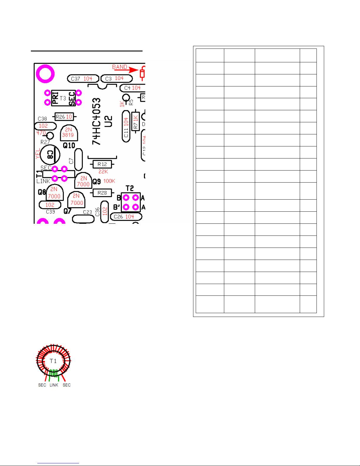
Coils an Transformers
You may fin it convenient to win an prepare all of the coils an transformers before you start inserting parts.
That way you on’t nee to stop an possibly loose concentration to win an them for installation. See page 5 for
ban specific etails.