QUALITY LIFTS Q4P09H Instruction manual

Rev 12/26/2013
Installation, Operation & Maintenance Manual
Four Post
Surface Mounted Lift
Models Q4P09H, Q4P09X & Q4P09W
(9,000 lb Capacity)
200 Cabel Street, P.O. Box 3972, Louisville, Kentucky 40201-3972
Email:[email protected] Web site:www.qualitylifts.com
Office 877-771-5438/ 502-583-5438 Fax 502-583-5488
IMPORTANT: READ THIS MANUAL COMPLETELY BEFORE
INSTALLING or OPERATING LIFT

Models Q4P09H, Q4P09X & Q4P09W
Installation, Operation and Maintenance
2 Rev 12/26/13
Q4P09-IOM-Q.doc
GENERAL SPECIFICATIONS
SPECIFICATIONS Q4P09H Q4P09X Q4P09W
ALength Overall 209½” [17’-5½”] 233½” [19’-5½”] 233 ½” [19’-5½”]
BWidth Overall 112¼” 112¼” 127¼”
CInside Columns 95” 95” 110”
DBetween Columns 160½” [13’-4½”] 184¾” [15’-4¾”] 184¾” [15’-4¾”]
EHeight of Columns 84½” 96½” 96½”
FHeight of Runways, Floor to Runway Top 7”min to 75-5/8" max 7”min to 87-7/8" max 7”min to 87-7/8" max
GWidth of Runways 20” 20 20
HWidth Between Runways 38” 38 38
IRise Height of Runway Top at Top Lock Position.
(allow 2-3/8” of clearance above top vehicle for lock release) 73¼” 85½” 85½”
Clear Height Underneath Runway (top lock position) 67 ¾” 80” 80”
JLength, Base Plate to Base Plate 179-1/4” 203-1/2” 203-1/2”
KMaximum Wheelbase * 155” 179” 179”
Lifting Capacity 9,000 lbs.
Motor: HP/Voltage, single phase std 1HP/115v or 2HP/220v
Speed of Rise (approximate) 120 Seconds/115v or 60 seconds/220v
Runway Length (not including mounting flange) 164” 188” 188”
* Wheelbase is based on a tire diameter of 30”
Fig 1 – General Specifications and Service Bay Layout

Models Q4P09H, Q4P09X & Q4P09W
Installation, Operation and Maintenance
3 Rev 12/26/13
Q4P09-IOM-Q.doc
Fig 2 – Drive Under Height

Models Q4P09H, Q4P09X & Q4P09W
Installation, Operation and Maintenance
4 Rev 12/26/13
Q4P09-IOM-Q.doc
WARNING
VERTICAL CLEARANCE
Check the height of the area where the lift is to be
installed. Clearance should be calculated based on
the full raised height of the lift.
Failure by purchaser to
provide adequate clearance
could result in
unsatisfactory lift performa nce, property
damage, or personal injury.
FLOORING
Be certain you have the proper concrete floor to
properly handle the loaded lift. Floor should be in
generally good condition with no large cracks,
spalling or deterioration.
Minimum requirements for concrete are 4
inches minimum depth, with steel
reinforcement, 3500 psi, cured fo r 28 days per
local commercial practice. This lift is designed to
accommodate a 3 inch total variation in elevation
at the base of the four posts. Floor should be level
within 1/2 inch from side-to-side and 2 1/2
front-to-rear to avoid special shimming. No
anchors should be installed within 8 inches of any
crack, edge, or expansion joint. If these conditions
cannot be met, a pad may be poured to
accommodate the lift.
Check with local building inspectors and/or permits
office for any special instructions or approvals
required for your installation.
Failure by purchaser to
provide the recommen ded
mounting surface could
result in unsatisfactory lift performance,
property damage, or personal injury.
LOCATION
This lift has been evaluated for indoor use only
with an operating ambient temp. range of 5 – 40°C
(41-104°F)
ELECTRICAL REQUIREMENTS
For lift installation and operation for single
phase units, it is necessary to have a dedicated
circuit with a single pole (11 5v) or Double pole
(230v) circuit breaker or time d elay fuse sized
for the following Full Load (FL) Amperage:
The 115V power unit FL amperage is 15 amps.
The 230V power unit FL amperage is 18 amps.
For lift installation and operation with standard
power unit, it is necessary to have a dedicated
115V single-phase 60-cycle circuit with a 20 amp
circuit breaker or time delay fuse
For lift installation and operation with 230V power
unit, refer to Fig 24.
SAFETY NOTICES AND DECALS
For your safety, and the safety of others, read and
understand all of the safety notices and decals
included here.
READ ENTIRE MANUAL BEFORE ASSEMBLING,
INSTALLING, OPERATING, OR SERVICING THIS
EQUIPMENT.
PROPER MAINTENANCE AND INSPECTION IS
NECESSARY FOR SAFE OPERATION.
DO NOT OPERATE A DAMAGED LIFT.
Safety decals similar to those shown here are
found on a properly installed lift. Be sure that all
safety decals have been correctly installed on the
Power Unit reservoir. Verify that all authorized
operators know the location of these decals and
fully understand their meaning. Replace worn,
faded, or damaged decals promptly.
Do not attempt to raise a
vehicle on t he lift until the
lift has b een correctly
installed and adjusted as described in this
manual.
WARNING
WARNING

Models Q4P09H, Q4P09X & Q4P09W
Installation, Operation and Maintenance
5 Rev 12/26/13
Q4P09-IOM-Q.doc
Receiving
The shipment should be thoroughly inspected as
soon as it is received. The signed bill of lading is
acknowledgement by the carrier of receipt in good
condition of shipment covered by our invoice.
If any of the goods called for on this bill of lading
are shorted or damaged, do not accept them until
the carrier makes a notation on the freight bill of
the shorted or damaged goods. Do this for your
own protection.
NOTIFY Quality Lifts AT ONCE if any hidden loss
or damage is discovered after receipt.
IT IS DIFFICULT TO COLLECT FOR LOSS OR
DAMAGE AFTER YOU HAVE GIVEN THE
CARRIER A CLEAR RECEIPT.
File your claim with Quality Lifts promptly.
Support your claim with copies of the bill of lading,
freight bill, and photographs, if available.
Fig 3 – Package Components
Component Packing List
ITEM
#
QTY/
LIFT DESCRIPTION
1 1 IDLER RUNWAY ASS’Y
2 1 POWER RUNWAY ASS’Y
3 1 POWER COLUMN ASS’Y
4 3 IDLER COLUMN ASS’Y
5 2 ENTRANCE RAMP
6 2 CROSS BEAM ASS’Y
7 1 POWER UNIT
8 2 FRONT WHEEL STOP
9 2 REAR WHEEL STOP
10 1 MECHANICAL LOCK BAR
11 8 SHIPPING HARDWARE
12 2 SHIPPING BRACKET WELD
INSTALLATION
IMPORTANT:Always wear safety glasses while installing lift.
TOOLS (MINIMUM REQUIRED)
a. Tape measure, 25ft
b. Chalk line
c. 4ft level
d. 10” & 12” adjustable wrench
e. Standard open end wrenches 3/8”, 7/16”, 1/2",
9/16”, 5/8”, (2) 11/16”, 3/4", 15/16”, 17mm
f. 6mm allen wrench
g. Box knife
h. Thread locking compound
i. Needle nose pliers
j. Hammer drill with 3/4” diameter carbide tipped
bits (Optional)
k. 2lb hammer
l. Torque wrench: 150 foot pounds minimum with
1 1/8” socket (Optional)
m. 8 ft. Step ladder
n. Blocking – (4) 4x4x30”, (4) 1x4x12”
o. Transit for leveling alignment lift.
p. Power Unit requires three gallons of clean
10wt anti-foam anti-rust hydraulic oil or Dexron
III ATF. DO NOT USE OILS WITH DETERGENTS
LAYOUT
1) Lay out the service bay according to the
architect’s plans or owners instructions (see
Fig 1). Be certain that the proper conditions
exist, see pages 2 & 3.
2) Unpack lift. Remove all packaging from Power
Runway (power runway has four cable
sheaves at rear end) and pull threaded cable
ends out. Make sure the cables are in the
proper sheaves at the 4-stack, Fig 6.
3) Remove the mechanical lock release bar from
the Idler Runway.

Models Q4P09H, Q4P09X & Q4P09W
Installation, Operation and Maintenance
6 Rev 12/26/13
Q4P09-IOM-Q.doc
4) Check the lock clevis to ensure it is secure and
that the lock pawl is in the correct position as
shown in Fig 4. Adjust the clevis if necessary.
Fig 4 – Lock Clevis
COLUMNS
5) Disassembly each column assembly place the
columns close to each corner per layout
(column with the power unit bracket goes at
the front left column per Fig 1).
6) With the runways spaced per Fig 1 and
blocked per Fig 7, using four 30” long 4x4’s
spanning the width of the runway and four 12”
long 1x4’s to shim up the jack-rail side of the
runway.
7) Lay the cross beams on the runway per Fig 5.
Place cardboard between the runway and
cross beam. Slide the column over the ends of
the slide blocks on the cross beam. Repeat for
each column.
8) With help, stand up the front and rear
column/cross beam assemblies.
Fig 5 – Column/Cross Beam Assembly
RUNWAY LAYOUT
Fig 6 – Power Runway 4-Stack (Rear View)
9) Remove the plastic caps from the hydraulic
bulkheads on the power runway and extend the
hydraulic cylinder fully. Take care not to kink the
cables.
NOTE: The cylinder can be extended by pulling
on the cylinder pull bar or by applying pressure
to the return port, per Fig 8.
10) Cable #1 & #2 should be extending out from
the rear of the power runway and cable #3 &
#4 from the front of the power runway, Fig 7.
11) Position the front and rear cross beams, Fig 7.
Fig 7 – Runway Layout

Models Q4P09H, Q4P09X & Q4P09W
Installation, Operation and Maintenance
7 Rev 12/26/13
Q4P09-IOM-Q.doc
WARNING
Fig 8 – Hydraulic Ports
12) Remove the four (4) cross beam sheaves
(one sheave from each end). The runway
sheave pins do not need to be removed.
13) Place the mechanical lock release rod into
the saddle on the idler side of the cross
beam, Fig 9.
Fig 9 – Mechanical Lock Rod
MAKE SURE THE CABLES ARE NOT
TANGLED WITH THE LOCK RELEASE
ROD INSIDE THE CROSSBEAM.
14) From the rear, route cable #1 from the top of
the left sheave stack through the access hole
and up out the left end of the rear cross
beam. Repeat for cable #2 from the bottom
of the right rear sheave stack through the
access hole and up out the right rear of the
rear cross beam, Fig 6 & 7.
15) At the rear of the power runway, continue
routing cables #3 & #4 to the front of the
power runway sheaves, Fig 10.
16) At the front of the power runway continue
routing cable #3 around the sheave and out
the front drivers side cross beam. Cable #4
should be routed around the sheave & out to
the passenger side front cross beam, Fig 11.
Ensure that cables 3 and 4 are not
crossed inside the front cross beam.
Fig 10 – Cable Layout
Fig 11 – Power Runway (Front View)
17) With runways and cross beams loose, attach
the mechanical lock bar to both cross beams
with the supplied hardware. Tighten once
cross beams are attached to the runways.
Verify the mechanical lock release moves
freely and lock pawl return spring doesn’t
interfere with Lock Ladder.(See Fig 4)
18) Reinstall the cross beam sheaves with one
plastic bearing washer and spacer on each
side of each sheave. Make sure the cables
are routed correctly around the slack cable
latch roller, per Fig 12.
Fig 12 – Slack Cable Routing
19) Attach both cross beams to the runways with
M12 x 35mm lg. bolts, lock washers and
washers (two at each end of each runway).
Install front wheel stops at the front of both
runways. Do not torque bolts yet.

Models Q4P09H, Q4P09X & Q4P09W
Installation, Operation and Maintenance
8 Rev 12/26/13
Q4P09-IOM-Q.doc
20) Check the layout of the lift in the bay. If
anchoring the lift, this is the last chance to
make adjustments. Adjust the position of the
runways so the distance from power side
jack rail to idler side jack rail is the same at
the front and the rear and the diagonal
measurements from the front tip of one rail to
rear tip of the opposite rail are within 1/4”,
Fig 13.
Fig 13 – Final Runway Positioning
21) Center cross beam bolts with slots in runway
and tighten. (Be careful not to move
runways.)
22) Reassembly the lock ladder and top cap to
column. Note: the lock ladder is offset from
the center of the threaded rod, and orientate
per Fig 14.
Fig 14 – Locking Ladder Orientation
23) Adjust the lock ladder so about 1½” remains
sticking out of the top. Tighten both bolts as
shown in Fig 15 when ladder is properly
orientated. Note: When adjusting the lock
ladder it may be necessary to loosen or
remove the bolts holding the top cap to the
column so the bottom nut can be adjusted.
Fig 15 – Lock Ladder Assembly
Fig 16 – Cable Jam Nut
24) Secure the cables to the top of the column
with the nut and jam nut provided, Fig 16.
25) Repeat for the remaining three columns.
ANCHORING
(OPTIONAL)
NOTE: Lift must be anchored in place if slope
is greater then 1/8” per 1 foot.
26) The anchor bolts must be installed at least 8”
from any crack, edge, or expansion joint.
27) Use a concrete hammer drill with a 3/4 inch
carbide bit. Tip diameter should conform to
ANSI Standard B94.12-1977 (.775 to .787).
Do not use excessively worn bits or bits
which have been incorrectly sharpened. A
core bit may be necessary if an obstruction is
encountered. Never substitute with shorter
anchor.
28) Drill the anchor holes using the base plate as
a template. Drill through the floor if possible
or to a depth of 5 inches minimum.
29) Vacuum dust from the hole for proper holding
power.
30) Shim columns to plumb using the shims
provided or steel washers. DO NOT shim
more than 1/2" at any given point. Use a level
no less than 24” in length to plumb columns.

Models Q4P09H, Q4P09X & Q4P09W
Installation, Operation and Maintenance
9 Rev 12/26/13
Q4P09-IOM-Q.doc
31) Assemble washer and nut to anchor with nut
just below impact section of bolt. Drive
anchor into hole until nut and washer contact
base. Tighten anchor bolts and recheck
column for plumb. Re-shim as required.
NOTE: Level bubble should not only be between
the lines, the bubble should be centered between
the lines. If shims do not allow sufficient centering
of the bubble, it is best to lean the rear columns in
the direction toward each other and the front
columns in the direction toward each other.
32) Install the four cable ends with one lock nut,
and one jam nut.
Power Unit
33) Install the Power Unit to the column using the
supplied M8x20mm bolts and M8 nuts. The
power unit can be installed on either the front
or side of the power column to suit install
location, shown in Fig 17.
Fig 17 – Power Unit
34) For installs on the front of the column (Fig
18), rout the power unit supply line to the
bulkhead shown below. Attach the 90
degree fitting at a slight angle downward and
secure the hose to the fitting.
Fig 18 – Supply Line, Front
35) Remove the 3/8-18 NPT plug on the side of
the power unit and attach the 90 degree
elbow at a slightly downward angle. Secure
the hose to the bulkhead shown in Fig 19.
Fig 19 – Return Line, Front
36) For installs with the power unit on the side of
the column route the supply line to the
bulkhead shown in Fig 20.
Fig 20 – Supply Line, Side
37) Remove the 3/8-18 NPT plug on the side of
the power unit and attach the 90 degree
elbow, Fig 21.
Fig 21 – Return Line, Side

Models Q4P09H, Q4P09X & Q4P09W
Installation, Operation and Maintenance
10 Rev 12/26/13
Q4P09-IOM-Q.doc
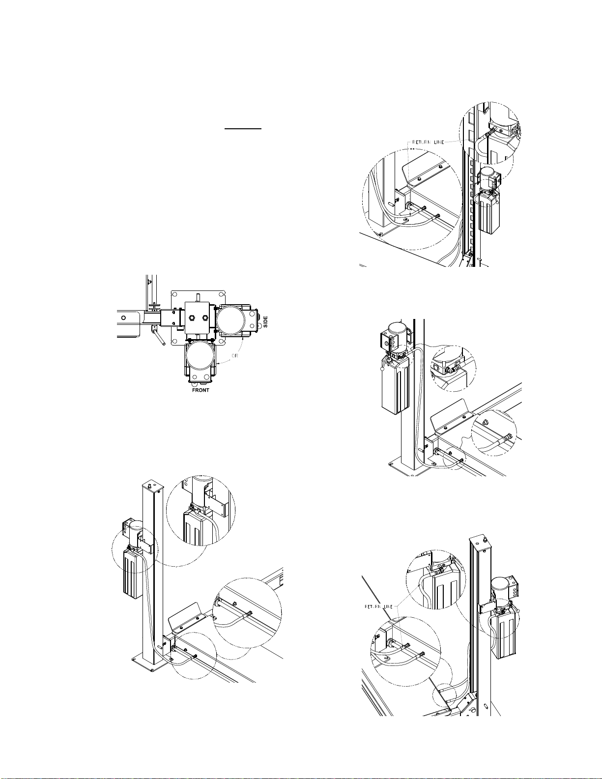
NOTE: When attaching the return line to the
bulk head i n the run way, make sure it is
securely attached at the power unit, and the
hose is not twisted or kinked into a position
that will lead to getting caught on the po wer
unit reservoir or the stud on the column
sides. Rais e the lift and carefully watch the
path the hose is riding u p the column, adjust
connection at the power unit and/or runway
bulkhead to allow the hose to move up
between the power unit and colum n. Make
sure the hose doesn’t catch on the column
caster lug as the lift rises.
38) Install O-Ring end of the straight hydraulic
fitting (9/16-18 O-Ring x M14x1.5-6g) to
power unit output port. Connect the
hydraulic hose to the hydraulic bulkhead
fitting in the power runway.
Do Not Use Teflon Tape or Pipe Dope on
fittings.
39) Connect the power unit to a suitable
electrical power source. The standard power
unit is 115 volt 50/60 Hz single phase
requiring a dedicated 15 amp single throw
circuit breaker to operate lift at full capacity.
40) BE CERTAIN ALL FITTINGS AND CONNECTIONS
ARE TIGHT. IT IS THE INSTALLERS
RESPONSIBILITY TO INSURE SYSTEM IS LEAK-
FREE. Fill the Power Unit with three gallons of
clean 10wt anti-foam anti-rust hydraulic oil or
Dexron III ATF. DO NOT USE OILS WITH
DETERGENTS.
41) Energize the power unit and raise the lift
approximately 1 ft off the ground and look
underneath the power runway to verify that
the cable lugs are resting firmly against the
cylinder pull bar.
42) To level the runways and crossbeams use a
4 ft. level. With the lift resting in its locks, find
the highest corner and adjust the other three
column ladder bars until the runways are
level front-to-rear and side-to-side. Tighten
jam nut against bottom side of each column
top plate.
43) Adjust cables until all four locks are
synchronized when lift is raised. Tighten
cable jam nuts against adjustment nuts.
44) Raise and lower lift several times to bleed
hydraulic cylinder. Hydraulic cylinder is self
bleeding. Lower lift and check fluid level in
reservoir. Add fluid as needed.
45) Run lift to full rise and continue running motor
approximately 5 more seconds. Check
hydraulic hose and connections for leaks.
Re-tighten fitting if leaking.
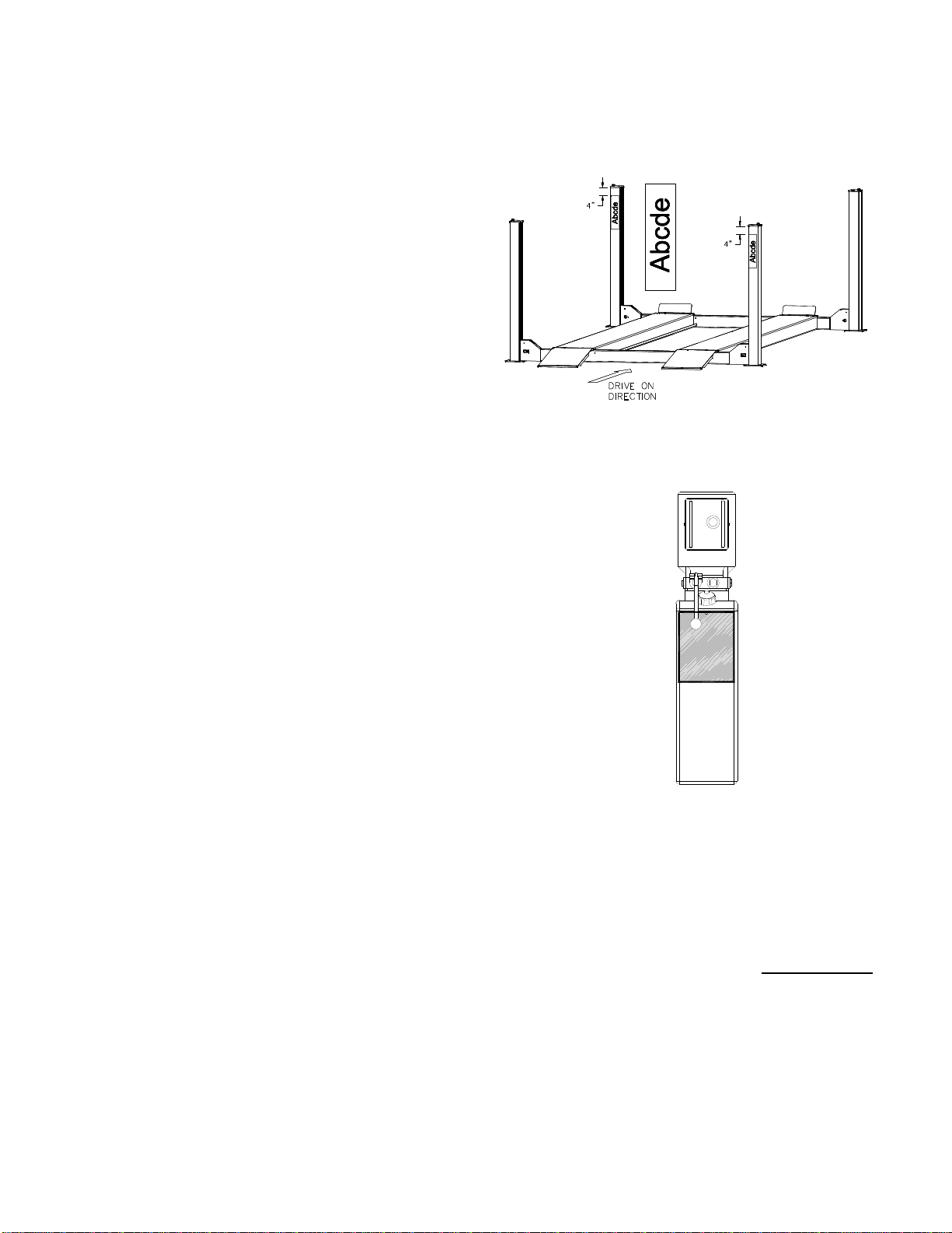
COLUMN DECAL PLACEMENT
46) Center the decal on the front drivers side
column and rear passenger side column.
47) Apply decal 4” from top of columns, Fig 22.
Fig 22 – Decal Placement
48) Place the Caution, Warning and Safety
Instructions decals seen on page 4, on the
power unit as shown, Fig 223.
Fig 23 – Power Unit Decal
OWNER/OPERATOR CHECKLIST
SAVE THESE INSTRUCTIONS deliver them to
owner/user/employee along with other materials
furnished with this lift.
49) Demonstrate the operation of the lift to the
owner/operator and review correct and safe
lifting procedures using the Lifting It Right
booklet as a guide.
50) Complete the Installation Checklist/Warranty
Validation questionnaire with the owner.
Review the terms of the warranty registration
card, and return the card and a copy for the
questionnaires to:
Quality Lifts, Inc.
P.O. Box 3944
Louisville, KY. 40206

Models Q4P09H, Q4P09X & Q4P09W
Installation, Operation and Maintenance
11 Rev 12/26/13
Q4P09-IOM-Q.doc
(Normally Open) M
FIELD
CONECTIONS
FOR SINGLE PHASE
Fig 24 – NON STANDARD 230V WIRING DIAGRAM
OPERATION PROCEDURE
SAFETY NOTICES AND DECALS
This product is furnished with graphic safety
warning labels, which are reproduced on
page 3 of these instructions. Do not remove
or deface these warning labels, or allow them
to be removed or defa ced. For your safety,
and the safety of others, read and understand
all of the safety notices and decals included.
OWNER/EMPLOYER RESPONSIBILITIES
This lift has been designed and constructed according to
ANSI/ALI ALCTV-2006 standard. The standard applies to
lift manufactures, as well as to owners and employers. The
owner/employer’s responsibilities as prescribed by
ANSI/ALI ALOIM-2000, are summarized below. For exact
wording refer to the actual standard provided with this
manual in the literature pack.
The Owner/Employer shall insure that lift
operators are qualified and that they are trained
in the safe use and operation of the lift using the
manufacturer’s operating instructions; ALI/SM
93 -1, ALI Lifting it Right safety manual; ALI/ST-
90 ALI Safety Tips card; ANSI/ALI ALOIM-2000,
American National Standard for Automotive Lifts-
Safety Requirements for Operation, Inspection
and Maintenance; ALI/WL Series, ALI Uniform
Warning Label Decals/Placards; and in case of
frame engaging lifts, ALI/LP-GUIDE, Vehicle
Lifting Points/Quick Reference Guide for Frame
Engaging Lifts.
The Owner/Employer shall establish
procedures to periodically inspect the lift in
accordance with the lift manufacturer’s
instructions or ANSI/ALI ALOIM-2000, American
National Standard for Automotive Lifts-Safety
Requirements for Operation, Inspection and
Maintenance; and the employer shall insure that
the lift inspectors are qualified and that they are
adequately trained in the inspection of the lift.
The Owner/Employer shall establish
procedures to periodically maintain the lift in
accordance with the lift manufacturer’s
instructions or ANSI/ALIOIM-2000, American
National Standard for Automotive Lifts-Safety
Requirements for Operation, Inspection and
Maintenance; and the employer shall insure that
the lift maintenance personnel are qualified and
that they are adequately trained in the
maintenance of the lift.
The Owner/Employer shall maintain the
periodic inspection and maintenance records
recommended by the manufacturer or ANSI/ALI
ALOIM-2000, American National Standard for
Automotive Lifts-Safety Requirements for
Operation, Inspection and Maintenance.
The Owner/Employer shall display the lift
manufacturer’s operating instructions; ALI/SM
93 -1, ALI Lifting it Right safety manual; ALI/ST-
90 ALI Safety Tips card; ANSI/ALI ALOIM-2000,
American National Standard for Automotive Lifts-
Safety Requirements for Operation, Inspection
and Maintenance; and in the case of frame
engaging lift, ALI/LP-GUIDE, Vehicle Lifting
Points/Quick Reference Guide for Frame
Engaging Lifts; in a conspicuous location in the
lift area convenient to the operator.
IMPORTANT SAFETY
INSTRUCTIONS
When using your garage equipment, basic safety
precautions should always be followed, including
the following:
1. Read all instructions.
2. Care must be taken as burns can occur from
touching hot parts.
3. To reduce the risk of fire, do not operate
equipment in the vicinity of open containers
of flammable liquids (gasoline).
4. Keep hair, loose clothing, fingers, and all
parts of body away from moving parts.
5. Use only as described in this manual. Use
only manufacturer’s recommended
attachments.
6. ALWAYS WEAR SAFETY GLASSES.
Everyday eyeglasses only have impact
resistant lenses, they are not safety glasses.

Models Q4P09H, Q4P09X & Q4P09W
Installation, Operation and Maintenance
12 Rev 12/26/13
Q4P09-IOM-Q.doc
SAVE THESE INSTRUCTIONS
LIFTING A VEHICLE
Place entrance ramps in the slotted holes on the
front of the ramp. Drive vehicle onto lift. Set the
parking brake. Remove entrance ramps before
lifting, and install removable wheel stops with
Wheel Side decal as shown in Fig 25.
Fig 25 – Removable Wheel Stops
When the vehicle has reached the desired working
height, release the power pack button, and lower
the vehicle until the safety locks are engaged. The
vehicle should remain level when all locks are
engaged. If one side engages and the other
continues to descend, stop lowering the vehicle,
raise it several inches, and try again to engage
locks.
IMPORTANT, Before walking under the lift insure
that all locks are properly engaged.
It is not safe to work under the vehicle unless all
locks are engaged, and the vehicle is level.
LOWERING A VEHICLE
Insure that the area under the vehicle is clear of
personnel and tools.
Raise the vehicle until locks are free.
Disengage the locks by rotating the mechanical
lock handle clockwise.
Lower the vehicle by depressing the lowering valve
handle and continue to hold mechanical lock
handle to keep locks disengaged. Watch lift to
insure that the lift is lowering evenly. If not, raise lift
and check all locks to insure they are disengaged
before trying to lower lift again.
Continue to lower the vehicle until the crossbeams
stop against the base plate. It is important to fully
lower the lift to release hydraulic pressure on the
system.
LOSS OF POWER
If for any reason, the lift will not raise off the locks
or the locks will not retract, consult factory
authorized personnel.
DO NOT OVERRIDE ANY SAFETY FEATURE IN
AN ATTEMPT TO LOWER THE LIFT.
MAINTENANCE
To avoid personal injury, permit only qualified
personnel to perform maintenance on this
equipment. Maintenance personnel should follow
lockout/tagout instructions per ANSI Z244.1.
The following maintenance points are suggested
as the basis of a routine maintenance program.
The actual maintenance program should be
tailored to the installation. See ANSI/ALI ALOIM
booklet for periodic inspection checklist and
maintenance log sheet.
If lift stops short of full rise or chatters, check
fluid level and bleed both cylinders per
Installation Instructions.
Replace all Safety, Warning or Caution Labels if
missing or damaged. (See Installation
instructions page 3.)
Daily
Keep lift components clean.
Check for loose or broken parts.
Check hydraulic system for fluid leaks.
Check lock release activation.
Weekly
Check cables and sheaves for wear or damage.
Replace as required with genuine Challenger
Lifts, Inc. parts.
Inspect lock mechanism for proper function.
Monthly
Torque concrete anchor bolts to 80 ft-lbs.
Clean and inspect cables and sheaves for wear
or damage. Lubricate cables and sheaves with
light oil.
Visually inspect concrete floor for cracks and/or
spalls within 12” of base plate
IMPORTANT ! Failure to keep lift free of
corrosive agents and solvents will lead to
reduced service life, which could result in
property damage and/or personal injury.
If any problems are encountered, contact
your local service representative.

Models Q4P09H, Q4P09X & Q4P09W
Installation, Operation and Maintenance
13 Rev 12/26/13
Q4P09-IOM-Q.doc
OPTIONAL ACCESSORIES
OIL DRIP TRAY (Q4P09DT)
1) Place drip tray between runways in the Jack
rail, Fig 26.
2) Slide along jack rail until its in desired location.
Fig 26 – Oil Drip Tray
STORAGE PLATFORM (Q4P09SP) CAPACITY 1000LBS
1) Up to four Storage Platforms can be placed
between the runways, Fig 27.
Fig 27 – Storage Platform
JACK TRAY (Q4P09JT), CAPACITY 4500LBS
1) The Jack Tray rests on the jack rails between
the runways. It can be positioned as needed
along the rail, Fig 28.
Fig 28 – Jack Tray
MOBILITY KIT (Q4P09CS)
1) This set of four casters when attached to the
cross beams of an unloaded lift, Fig 29, pick
the lift up and allow it to be rolled to a different
location.
Fig 29 – Mobility Kit
HAND OPERATED ROLLING JACK (QRJ04H)
1) Move the jack into under vehicle and extend
the arms to the pick up points.
2) Make sure the lowering valve is closed all the
way by turning the knob clockwise, Fig 30.
3) Raise vehicle desired height, rest the jack in
one of the jack locks.
4) To lower, pump the jack to raise it enough to
disengage the lock, and turn the lowering knob
counter-clockwise.
Fig 30 – Rolling Jack
EXTENDED ALUMINUM RAMPS (Q4P09ER)
1) Install in the runway by placing the two studs in
the slotted holes.
2) Remove before raising the lift.

Models Q4P09H, Q4P09X & Q4P09W
Installation, Operation and Maintenance
14 Rev 12/26/13
Q4P09-IOM-Q.doc
PIVOTING RAMP (Q4P09PR)
1) Raise the lift to a comfortable working height
and set into the locks.
2) Remove the M12 bolt, lock washer & washer
attaching the runway to the crossbeam, and
retain the lock washer & washer for installation
of the pivot ramp base.
3) Install the pivoting ramp base with two M12 x
40mm Lg. and two M12x35mm Flange head
bolts, washers and nuts provided in the kit, and
the lock washer and washer from the previous
step, Fig 31. Note the location of flange head
bolt in Fig 31. Repeat for other runway.
Fig 31 – Base Installation
4) Turn the ramp over and install the ramp
rotation stop as shown in Fig 32. Use the
provided M12 x 30mm Lg. bolt and M12 nut.
5) Place the stop on the gusset as shown in Fig
32, assembly the nut onto the bolt prior to
installing the bolt into the stop. Torque the bolt
against the ramp gusset and lock into place
with the nut.
Fig 32 – Rotational Stop
6) Assemble the ramp to the base with the ramp
hinge pin. Use the provided cotter pins to
secure the pin in place, Fig 33.
Fig 33 – Ramp Installation

Models Q4P09H, Q4P09X & Q4P09W
Installation, Operation and Maintenance
15 Rev 12/26/13
Q4P09-IOM-Q.doc
Parts Breakdown
Models Q4P09H, Q4P09X & Q4P09W
IMPORTANT!!!
Replace all worn or broken parts with genuine Quality Lifts Inc. parts.
Contact your local Quality Lifts Parts Distributor for pricing and availability.
(Call Quality Lifts Inc. (502) 583-5438 for the Parts Distributor in your area)

Models Q4P09H, Q4P09X & Q4P09W
Installation, Operation and Maintenance
16 Rev 12/26/13
Q4P09-IOM-Q.doc
Parts Breakdown
Fig A. General Layout

Models Q4P09H, Q4P09X & Q4P09W
Installation, Operation and Maintenance
17 Rev 12/26/13
Q4P09-IOM-Q.doc
ITEM #
PART # QTY/LIFT
DESCRIPTION
1 TCS4-08-01-00A 1 IDLER RUNWAY WELD (Q4P09H)
TCS4A-08-01-00 (Q4P09X & W)
2 TCS4-07-01-00A 1 POWER RUNWAY WELD (Q4P09H)
TCS4A-07-01-00 (Q4P09X & W)
3 TCS4-01-00-xx 1 POWER COLUMN ASSY
-xx = COLOR CODE (Q4P09H)
TCS4A-01-00-xx (Q4P09X & W)
4 TCS4-02-00-xx 3 IDLER COLUMN ASSY
-xx = COLOR CODE (Q4P09H)
TCS4A-02-00-xx (Q4P09X & W)
5 TCS4-09-00B 2
ENTRANCE RAMPS
(use p/n Q4P09SR for one pr of std ramps/ p/n Q4P09ER for pr Long ramps
6 AB-7816-1 1 POWER UNIT, 115v, SINGLE PHASE, 50/60Hz
31368-19 POWER UNIT, 220v, SINGLE PHASE, 60Hz
7 X10-048 4
M8 NUT
8 MR6-007 4
M8 x 20mm Lg. HEX HD CAP SCREW
9 TCS4-13 2
9/16 O-RING x M14x1.5 90 DEGREE HYD. FITTING
10 TCS4-15 1
HOSE – RETURN (91”)
11 JSZ5-5-10-04 1
HOSE – SUPPLY (67”)
12 TCS4-07-08 1
HOSE – SHORT RETURN
13 JSZ5-5-10-03 1
HOSE - HYDRAULIC CYLINDER
14 TCS4-07-07 1
STRAIGHT HYD. FITTING
15 TCS4-03-00 1 HYDRAULIC CYLINDER ASSEMBLY (Q4P09H)
TCS4A-03-00 (Q4P09X & W)
16 JSZ5-5-10-06 2
M14x1.5 BULKHEAD NUT
17 JSZ5-5-10-05 2
M14 BULKHEAD FITTING
18 B40082 1
CLEVIS PIN
19 B40126 1
1/8 x 1½” Lg. COTTER PIN
20 TCS4-07-06 1
MECHANICAL LOCK BAR HOLDER
21 VS10-10-25 2
M8 x 12mm Lg. PHILLIPS PAN HEAD SCREW
22 TCS4-07-05-00 1
CABLE PULL BAR
23 JSZ5-5-03-03-03 2
CABLE PULL BAR SLIDE BLOCKS
24 Q4P09-001 4
M6 x 20mm Lg. COUNTER SUNK SCREWS
25 Q4P09-002 1
M24 NYLON LOCK NUT
26 Q4P09-003 1
M24 WASHER
27 B40083 8
M12 x 35mm Lg. HEX FLG. HD. CAP SCREW
28 X10-039 8
M12 LOCK WASHER
29 X10-038 8
M12 WASHER
30 B40266 2
WHEEL STOP
31 TCS4-12-00 2
REMOVABLE WHEEL STOP
32 JSJ3-10-05 1
3/8-18 NPT x M14x1.5 90 DEGREE HYD. FITTING
Replace all worn or broken parts with genuine Quality Lifts Inc. parts.
Contact your local Quality Lifts Parts Distributor for pricing and availability.
(Call Quality Lifts Inc. (502) 583-5438 for the Parts Distributor in your area)

Models Q4P09H, Q4P09X & Q4P09W
Installation, Operation and Maintenance
18 Rev 12/26/13
Q4P09-IOM-Q.doc
PARTS BREAKDOWN (continued)
Fig B. Cables
ITEM #
PART # QTY/LIFT
DESCRIPTION
33A TCS4-11-02 1 PASSENGER SIDE REAR CABLE
Cable #2
(174 7/8”) (Q4P09 H)
TCS4A-11-02 (187”) (Q4P09 X)
TCS4B-11-02 (194 ½”) (Q4P09 W)
33B TCS4-11-04 1 PASSENGER SIDE FRONT CABLE
Cable #4
(353 5/8”) (Q4P09 H)
TCS4A-11-04 (389 ¾”) (Q4P09 X)
TCS4B-11-04 (397 ¼”) (Q4P09 W)
33C TCS4-11-03 1 DRIVER SIDE FRONT CABLE
Cable #3
(295 5/8”) (Q4P09 H)
TCS4A-11-03 (332”) (Q4P09 X)
TCS4B-11-03 (339 ½”) (Q4P09 W)
33D TCS4-11-01 1 DRIVER SIDE REAR CABLE
Cable #1
(117 1/8”) (Q4P09 H)
TCS4A-11-01 (129 ¼”) (Q4P09X)
TCS4B-11-01 (136 ¾”) (Q4P09W)
34 TCS4-01-03-00 4 LOCK LADDER (Q4P09H)
TCS4A-01-03-00 (Q4P09X & W)
35 MR6-005 4
M20 NUT
36 Q4P09-004 4
M20 LOCK NUT
37 VS10-40-17 8
M12 x 35mm Lg. HEX FLG. HD. CAP SCREW
38 X10-038 8
M12 WASHER
39 X10-039 8
M12 LOCK WASHER
40 X10-040 8
M12 NUT
41 Q4P09-010 8
M22x2.5 NUT
Replace all worn or broken parts with genuine Quality Lifts Inc. parts.
Contact your local Quality Lifts Parts Distributor for pricing and availability.
(Call Quality Lifts Inc. (502) 583-5438 for the Parts Distributor in your area)

Models Q4P09H, Q4P09X & Q4P09W
Installation, Operation and Maintenance
19 Rev 12/26/13
Q4P09-IOM-Q.doc
PARTS BREAKDOWN (continued)
Fig C. Runway Sheaves
ITEM #
PART # QTY/LIFT
DESCRIPTION
45 40053 12
1/8” THICK BEARING
46 TCS4-04-03-00 6
SHEAVE ASSEMBLY
47 TCS4-07-04-00 4
SHEAVE PIN ASSEMBLY (RUNWAY)
48 B31188 4
M8 x 16mm Lg. HEX LOCKING FLG. HD. CAP SCREW
49 TCS4-07-03 2
RUNWAY SHEAVE SPACER – TALL
50 TCS4-07-02 2
RUNWAY SHEAVE SPACER - SHORT
Replace all worn or broken parts with genuine Quality Lifts Inc. parts.
Contact your local Quality Lifts Parts Distributor for pricing and availability.
(Call Quality Lifts Inc. (502) 583-5438 for the Parts Distributor in your area)

Models Q4P09H, Q4P09X & Q4P09W
Installation, Operation and Maintenance
20 Rev 12/26/13
Q4P09-IOM-Q.doc
PARTS BREAKDOWN (continued)
Fig D. Cross Beams
This manual suits for next models
2
Table of contents
Other QUALITY LIFTS Lifting System manuals
Popular Lifting System manuals by other brands

JLG
JLG 1350SJP Operation and safety manual

Maxon
Maxon BMR Series installation manual

Southworth
Southworth PalletPal 360Air owner's manual

Braun
Braun NCL Century 2 Series Operator's manual

Ravaglioli
Ravaglioli RAV260 Translation of the original instructions

Jungheinrich
Jungheinrich ECE 118 operating instructions