MOTOR1 MOTOR2 MOTOR3 MOTOR4
ENC 1 ENC 2 ENC 3 ENC 4
MOTOR1 MOTOR2 MOTOR3 MOTOR4
ENC 1 ENC 2 ENC 3 ENC 4
Using the RCA to RCA cable, connect
Analog Output Channel (AO) #0 on
the data acquisition (DAQ) device to the
Amplifier Command #0 connector on
the amplier. Similarly, connect AO #1
and #2 on the DAQ device to Amplifier
Command #1 and #2 on the amplier.
D
Using the 3-pin-DIN to 4-pin-DIN motor
cable, connect the TO LOAD #0 on the
amplier to the Motor 1 connector on
the 3 DOF Gyroscope. Similarly, connect
TO LOAD #1 and #2 on the amplier
to Motor 2 and Motor 3 on the 3 DOF
Gyroscope.
Turn ON the AMPAQ-L4’s power switch.
It is located on the rear of the device.
System Power
E-Stop
Enabled
Amplifier Command
(1.0V = 0.5A)
(1.0V = 0.5A)
Current Sense
To Load (2.5A ±24V)
(0.5x Amplifier Command) AMPAQ -L4
MULTI CHANNEL LINEAR CURRENTAMPLIFIER
WWW.QUANSER.COM
MADEIN CANADA
Amplifier 0 Amplifier 2 Amplifier 3Amplifier 1
This device complies with Part 15 of the FCC
Rules. Operation is subject to the following two
conditions: (1) this device may not cause harmful
interference, and (2) this device must accept any
interference received, including interference that
may cause undesired operation.
This Class A digital apparatus complies with
Canadian ICES-003.
Cet appareil numérique de la classe A est
conforme à la norme NMB-003 du Canada.
100-120 V~ or
200-240 V~
4.1A
50/60Hz, Class 1
Fuse: 5.0A 3AG, 250V
Slow-Blow
F
U
S
E
F
U
S
E
Analog
Output
(AO)
0
Analog
Output
(AO)
1
Analog
Output
(AO)
2
Data Acquisition (DAQ) Device
3 DOF Gyroscope
3 DOF Gyroscope
Amplifier
System Power
E-Stop
Enabled
Amplifier Command
(1.0V = 0.5A)
(1.0V = 0.5A)
Current Sense
To Load (2.5A ±24V)
(0.5x Amplifier Command) AMPAQ -L4
MULTI CHANNEL LINEAR CURRENTAMPLIFIER
WWW.QUANSER.COM
MADEIN CANADA
Amplifier 0 Amplifier 2 Amplifier 3Amplifier 1
Amplifier
Amplifier (rear)
Using the 5-pin DIN to 5-pin DIN encoder
cable, connect the Encoder #0 (ENC #0)
on the data acquisition device to the
ENC 1 connector on the 3 DOF Gyroscope.
Similarly connect ENC 1 and ENC 2
on the data acquisition device to ENC 2
and ENC 3 on the 3 DOF Gyroscope.
Encoders
(EI Channel
#0)
Encoders
(EI Channel
#1)
Encoders
(EI Channel
#2)
Data Acquisition (DAQ) Device
01 2
F
G
E
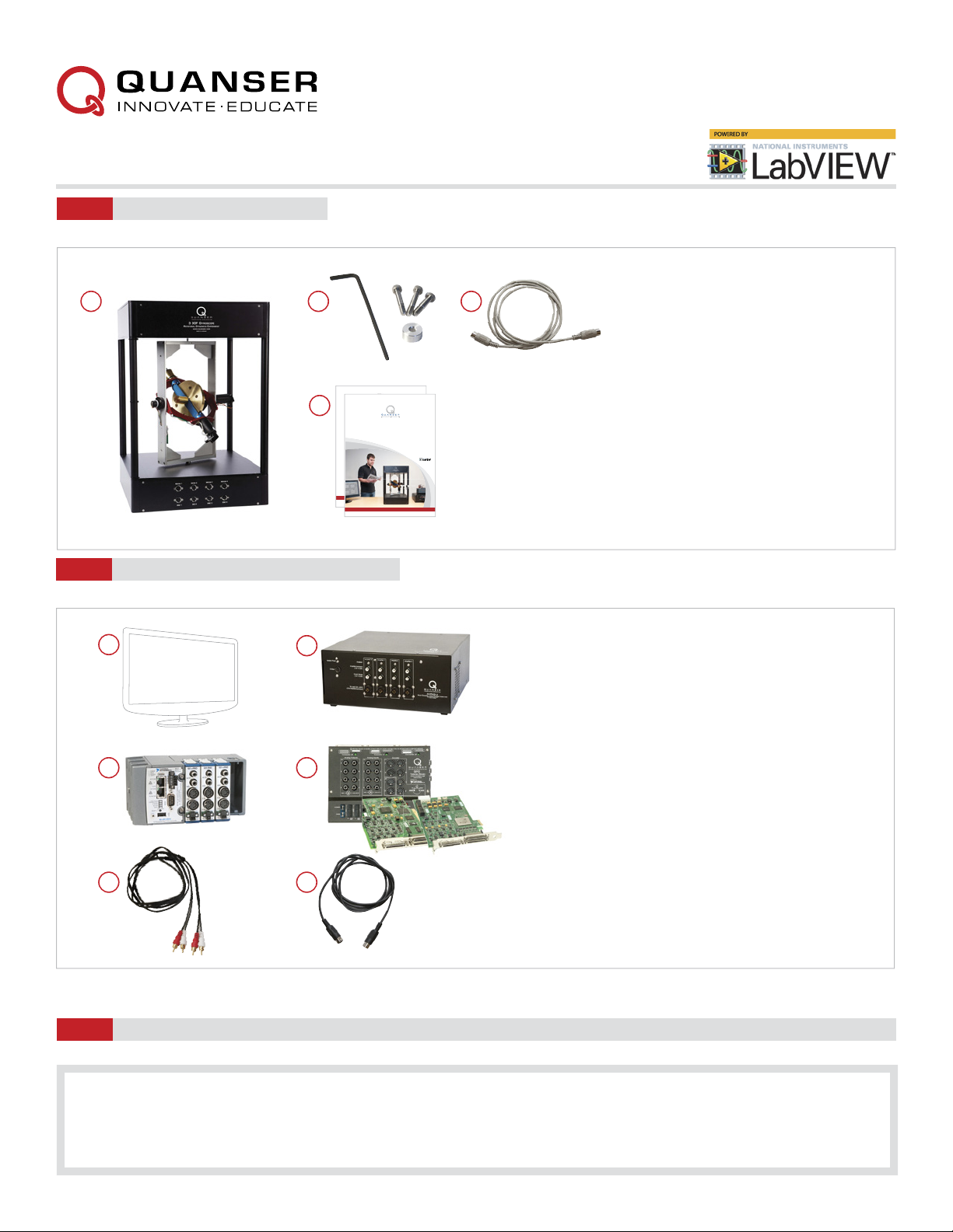
Set Up the Hardware
STEP 4
Follow the procedure below to set up your 3 DOF Gyroscope experiment. The connections shown below are illustrated using a generic data
acquisition (DAQ) device and an AMPAQ-L4 amplifier (you may have a different DAQ or amplifier). For detailed instructions, see the 3 DOF
Gyroscope User Manual
Your data acquisition (DAQ) device should be already
set up and tested as dictated in its corresponding Quick
Start Guide.
Make sure everything is powered off before making any
of these connections. This includes turning OFF your PC
and the amplier.
AB
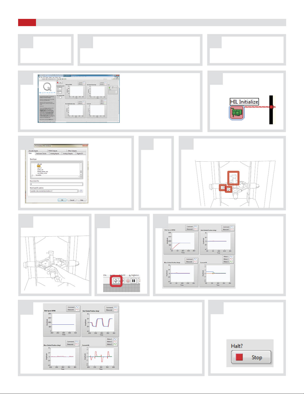
CWith the M4-15 mm screw and the spacer,
lock the silver frame by using the locking
holes on top of the frame (any of them)
and the upper enclosure. The spacer
should be placed and aligned between the
silver frame and the upper enclosure such
that the M4-15mm screw goes through it.