Quantel Medical Axis II PR User manual

XE AX2 MT AN OCTOBER 2009
OPHTHALMIC ECHOGRAPH
BIOMETRY AND PACHYMETRY
SERVICE MANUAL
QUANTEL MEDICAL
Head Office: 21, rue Newton, Z.I. du Brezet, 63039 Clermont-Ferrand cedex 2 - FRANCE
Tel : +33 (0) 473 745 745 - Fax : +33 (0) 473 745 700
Directive 93/42/EEC
2003


Rev 10-2009
SERVICE MANUAL
P - 3
WARRANTY :
* Any adjusment and calibration procedure described in this manual shall be performed
by QUANTEL MEDICAL authorized technicians only or by personnel who has been
previously trained by QUANTEL MEDICAL.
* Any faulty part will be replaced by a strictly identical one provided by QUANTEL
MEDICAL.
* For safety reasons, QUANTEL MEDICAL considers any electronic board as a whole
partial assembly :
* Defective boards must be returned to QUANTEL MEDICAL for replacement.
* Warranty will be void if a board has been damaged during maintenance or attempt to
repair.
Warranty will be void unless these recommendations are strictly respected.
WARNING:
Special training delivered by QUANTEL MEDICAL is required for technicians prior
to performing maintenance on the equipment in order to ensure optimum
adjustment and maximum reliability of the whole instrument.
WARNINGS
IMPORTANT: Before performing any maintenance or repair on the equipment,
ensure that all the system/user configuration and parameters are saved in
order to be restored after if needed.

Rev 10-2009
SERVICE MANUAL
P - 4
Page Rev 10-2009
WARNINGS ................................................................................ 3
TABLE OF CONTENTS ............................................................. 4 X
1- TECHNICAL SPECIFICATIONS ............................................ 5
1-1 Electrical requirements ............................................................................... 5 X
1-2 Environmental conditions ............................................................................ 5
1-3 Housing material ......................................................................................... 5
1-4 Spare parts ................................................................................................. 6
2- INSIDE ACCESS .................................................................... 7
2-1 External view ............................................................................................... 7
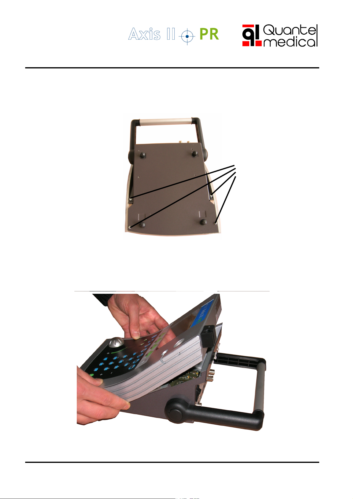
2-2 How to open the case ................................................................................. 8
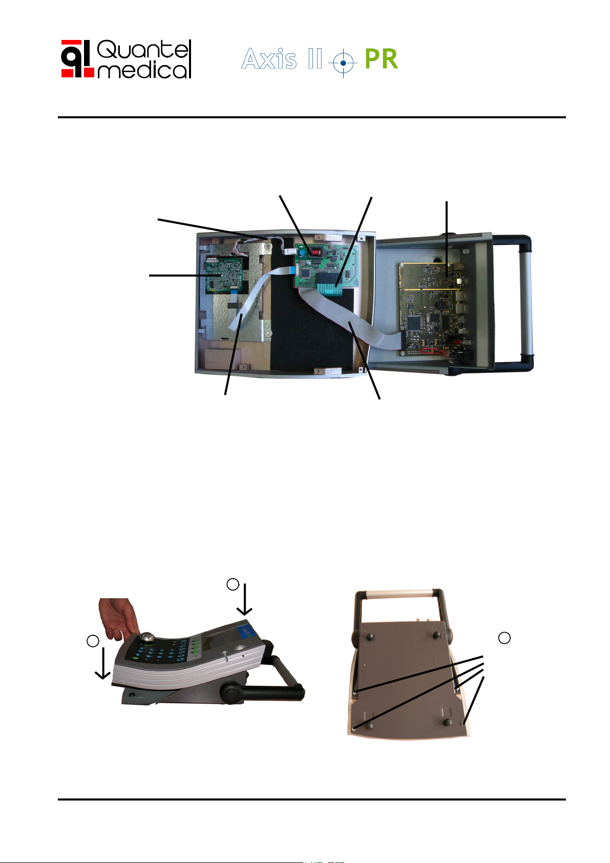
2-3 Inside view .................................................................................................. 9
2-4 How to close the case ................................................................................ 9
3- BOARD DESCRIPTION ....................................................... 10
3-1 Block diagram ........................................................................................... 10
3-2 CPU board ................................................................................................ 11
3-3 Replacing a CPU board ............................................................................. 12
3-4 Replacing a video interface board .............................................................. 13
3-5 Replacing an LCD screen ......................................................................... 14
4- SERVICE MODE .................................................................. 15
4-1 Hidden page access ................................................................................. 15
4-2 Field description........................................................................................ 15
4-3 Activating the Post-refractive feature ......................................................... 19
4-4 General reset ............................................................................................ 19
5- PROBE CALIBRATION ........................................................ 20
5-1 Biometry probe ......................................................................................... 20
5-2 Pachymetry probe ..................................................................................... 20
6- SOFTWARE UPGRADE ....................................................... 21
6-1 Software version compatibility ................................................................... 21
6-2 Upgrading to V5.0 ..................................................................................... 21
6-3 Upgrading to V4.04 ................................................................................... 21
6-4 Upgrading to V3.xx, 2.xx or 1.xx .............................................................. 21
6-5 How to install a new software version ........................................................ 22
7- TROUBLESHOOTING ......................................................... 28
APPENDIX A- EVOLUTION OF THE CONFIGURATION ........ 29
VALIDATION ............................................................................. 37 X
TABLE OF CONTENTS

Rev 10-2009
SERVICE MANUAL
P - 5
1 - TECHNICAL SPECIFICATIONS
- Power supply: External module with automatic voltage adaptation,
no selection is needed.
Input Voltage: 110 to 230 Vac ± 10%
single phase without earth
Frequency: 50 or 60 Hz
Mains consumption: 20 VA
AXIS-II consumption: 5.4 W (450mA on 12Vdc)
Class II Power Supply: Reinforced Isolation.
- References: SSL20-7612 Trade Mark: ARTESYN
Technologies
or ESS36US12-1E Trade Mark: XP POWER
or TR30M120-01E03 Trade Mark: CINCON
- Compliance: Power supply and enclosure designed per IEC 60601-1
European directive: 93/42/CEE
Electromagnetic compatibility: IEC 60601-1-2
1-1 ELECTRICAL REQUIREMENTS
1-2 ENVIRONMENTAL CONDITIONS
The temperature of the room where the device is operated must be within the
following range:
50°F < T° < 95°F (10 °C < T° < 35 °C)
The relative humidity must not exceed 95% without condensation.
The Device storage and transport temperature must be within the range:
- 4°F < T° < 158°F (-20 °C < T° < 70 °C)
1-3 HOUSING MATERIAL
Upper frame: Polystyrene PS CHOC complies with UL 94 VO standard
Lower frame: Painted steel sheet
LCD front panel: Polycarbonate

Rev 10-2009
SERVICE MANUAL
P - 6
1 - TECHNICAL SPECIFICATIONS
1-4 SPARE PARTS
PARTS LIST
REFERENCE DESCRIPTION
XE AX2 CABLE RS232 RS232 Cable
XE AX2 CPU Main Board for V1.xx
XE AX2 CPU V2 Main Board for V2.xx
XE AX2 CPU V3 Main Board for V3.xx
XE AX2 CPU V5 Main Board for software V4.xx and
V5.xx
XE AX2 LCD B&W LCD screen
XE AX2 LCD COLOR Color LCD screen
XE AX2 PCB VIDEO Video Interface Board for V1.xx &
V2.xx
XE AX2 PCB VIDEO V3 Video Interface Board for V3.xx
XE AX2 PCB VIDEO V5 Video Interface Board for V4.xx
&V5.xx
XE AX2 PLEXI Plexiglas Screen
XE AX2 FAV CLV Plastic housing with Keyboard
XL VIT BOUTON Knob
ACCESSORIES/OPTIONS LIST
REFERENCE DESCRIPTION
XE AX2 EXT POW Power Supply : SSL20-7612 /
Artesyn
XE AX2 PRB BIO TP-01-b probe
XE AAA PAM Hand-piece for biometry probe
XE PRB BIO L Biometry probe with laser pointer
XE AAA PRB PK Pachymetry probe
XE AX2 OPT PK Pachymetry option
XE AAA PED Pedal
XE AX2 TEST BLOC Test block (Biometry)
XE AX2 PSD PK Pachymetry probe holder +
test block
XE CLV USB AZ External USB Keyboard (AZERTY)
XE CLV USB QW External USB Keyboard (QWERTY)
XE HUB USB USB Hub
XE CLE USB USB storage Key
XE AX2 HOUSSE Dust Cover
XE AX2 VALISE Axis-II Bag
Important: when ordering a spare part, the device serial number and the software
version must be provided.

Rev 10-2009
SERVICE MANUAL
P - 7
2 - INSIDE ACCESS
2-1 EXTERNAL VIEW
Pachymetry probe
holder and test-block
Biometry probe
on its holder
Color LCD screen
Knob : Digital Potentiometer
Screen
Function Keys
Function keys
Built-in
Alpha-numeric Keyboard
Pedal key
Biometry probe
test-block
Handle

Rev 10-2009
SERVICE MANUAL
P - 8
2 - INSIDE ACCESS
2-2 HOW TO OPEN THE CASE
- From the bottom panel, unscrew the 4 screws as shown.
Axis-II Bottom view
Hood
- Put the device on the normal position and lift up the upper part of the
case verticaly as shown.
4 screws to
be removed

Rev 10-2009
SERVICE MANUAL
P - 9
2 - INSIDE ACCESS
2-3 INSIDE VIEW
CPU board
LCD screen
Video interface board
Ribbon cable between the
LCD screen and the video
interface board
2-4 HOW TO CLOSE THE CASE
- Put the cover back from the top side (1) first then the other side (2). Put
the device up-side-down and tighten the 4 screws (3).
1
2
4 screws to be
tightened
3
Backlight cable
Ribbon cable between the
video interface board and
the CPU board
Keyboard
ribbon cable

Rev 10-2009
SERVICE MANUAL
P - 10
3 - BOARD DESCRIPTION
3-1 BLOCK-DIAGRAM
TP-01-b Probe
Main Board
Liquid Crystal
Display
Footswitch
Interface
Board
Pulser
Knob
Receiver
Programmable
Logic Device
(PLD)
A. D.
Converter
Microcontroller
(68328)
RS 232 Ports USB Ports
Flash
memory
Hard Disk
External Power Supply
Class II / 12 V
Mains :
100 to 230 V ~
Clock :
Date &
Time
RAM
Patient
Data
#1 #2 #1 #2
Pulser
P1 Probe
Receiver
Keyboard

Rev 10-2009
SERVICE MANUAL
P - 11
3 - BOARD DESCRIPTION
Ribbon Cable 1
Link to the Keyboard Interface via the ribbon
cable with 20 wires.
Important : pin # 1 is red
Probe connector :
Lemo / 4 pins
BNC
connector
for
Pachymetry
probe
RS232 ports
# 2 # 1
12 VDC
Power
switch
Analog part
(Biometry filter)
3-2 CPU BOARD
USB #2 USB #1
Analog part
(Pachymetry filter)
Buzzer
ACEX
(EPLD)
RAM
Microprocessor
Pedal
connector
XEAX2CPUV5

Rev 10-2009
SERVICE MANUAL
P - 12
3 - BOARD DESCRIPTION
3-3 REPLACING A CPU BOARD
Remove the 4
screws
1
2
3
Unplug the
power and
ground
connectors
Disconnect the
ribbon cable
4Pull the board
in this direction
5To replace the board, perform the
steps above in reverse order
Warning: the faulty board must be returned to QUANTEL MEDICAL as a
whole without unmounting or opening any component. Failure to comply
will void the equipment warranty.
XEAX2CPUV5

Rev 10-2009
SERVICE MANUAL
P - 13
3 - BOARD DESCRIPTION
3-4 REPLACING A VIDEO INTERFACE BOARD
Remove the
screw
2
Unplug the
connectors
3
To replace the board, perform the
steps above in reverse order
4Remove the board
Warning: the faulty board must be returned to QUANTEL MEDICAL as a
whole without unmounting or opening any component. Failure to comply
will void the equipment warranty.
Remove the knob by
pulling it vertically then
unscrew the nut
underneath
1
5
XEAX2PCBVIDEOV5

Rev 10-2009
SERVICE MANUAL
P - 14
3-5 REPLACING AN LCD SCREEN
Remove the 2
screws
1
2
Unplug the
cable
connectors
3
Pull the board in
this direction
to remove it from
the notches
4
5To replace the board, perform the
steps above in reverse order
Warning: the faulty board must be returned to QUANTEL MEDICAL as a
whole without unmounting or opening any component. Failure to comply
will void the equipment warranty.
3 - BOARD DESCRIPTION
Note:Ribbon
blue mark is up
Note: Before disconnecting the ribbon cable, note the polarizing position
(blue side up) for future reconnection. On the V5 board, the ribbon cable
can be disconnected from both end while on earlier version boards, the
cable can be removed only on one end.
Unplug the
ribbon cable
connector
Note:Ribbon
blue mark is up
Board notches
XEAX2LCDCOLOR

Rev 10-2009
SERVICE MANUAL
P - 15
4 - SERVICE MODE
4-1 HIDDEN PAGE ACCESS
Test
GENERAL SETUP
Serial Output (1) : Not Used
Position of marker # 1 in Contact : +0.00 mm
Language : English
Day : Nov/19/2007
Time : 09:53:20
Appearence : Model 3
Serial Number :####-#### ID:#### 03/09/07
Information :
Quantel Medical AXIS II V5.xx
Zero:16 PR Option : YES
Retina Slope Test : 6
D2 / Low Dyn (dB) : 20
Noise : 0
Pachy Option : NO
KeyCode: 0
Delete Back Space CAPS/Small
AXIS-II PR - P version:5.00
Sept/03/2007 18:53:00
User
#1 User1
#2 User2
#3 User3
#4 User4
#5 User5
Volume adjustment (-/+): 30%
Contrast Adjustment(</>): 40%
Gral SETUP USER Setup Pachymetry
123
Press F1 Move cursor on
“Language” filed
and press
The hidden screen
is then displayed
Serial Number :####-#### ID:#### 03/09/07
Information :
Quantel Medical AXIS II V5.xx
Zero:16 PR Option : YES
Retina Slope Test : 6
D2 / Low Dyn (dB) : 20
Noise : 0
Pachy Option : NO
KeyCode: 0
Delete Back Space CAPS/Small
4-2 FIELD DESCRIPTION
Serial number, required for
pachymetry activation (refer to the
activation guide XE AX2PK NI).
To be adjusted according
to the manufacturer of
the probe and to be used
to activate the PR option
(see section 4-3).
Keycode to be entered to
activate the pachymetry option
(refer to the activation guide).
To be adjusted for a right
noise level in biometry
mode (see section 4-2-4
“Noise level setting”) and
to be used for general
reset (see section 4-4
“General reset”).
Information field. Use F2
(delete character), F3
(backspace) and F4 (Caps/
small) to enter characters.

Rev 10-2009
SERVICE MANUAL
P - 16
4 - SERVICE MODE
4-2-1 Field “ZERO” and Position of Marker #1
The default value of this field is “16” and is given by the manufacturer of
the biometry probe. This value can be different with another manufacturer
and it depends on the size of the probe tip.
Adjusting “Zero” will impact the mesured values during acquisition as
follows:
- decreasing ZERO by 1 will increase the mesured value by 0.04mm (with
the “Position of marker #1 in contact” of the general setup page as
0.00mm).
The test block has been developed as a standard in contact technique to
calibrate the measurement of the eye and adjust the corresponding
parameters. Follow the steps below to enter the correct value in “Zero”.
1. Make a biometry acquisition on the test-block:
- from the Main page, press F1 to go to the General Setup page,
- move the cursor to “Position of marker #1 in contact”
- press F1 and follow the instructions on the screen as below:
Put the probe on the Test-Block
With a drop of water.
Press "F1" to Start
and then to Stop the measurements.
Note : the result is corrected by
the position of the first marker : +0.00 mm
Best = 10.04 mm
L = 10.08 mm
2. The mesured value X (displayed as “Best”) must be
10.00 < X < 10.11mm
3. If X is not within this interval, modify ZERO so that X will fit into these
limits (knowing that 1 unit of ZERO corresponds to 0.04mm of X).
Ex: X=9.96mm, ZERO can be adjusted to: 12 < ZERO =< 15
Note: Instead of modifying ZERO, this correction can also be done by
entering the value in the “Position of marker #1 in contact” field of the
general setup page.

Rev 10-2009
SERVICE MANUAL
P - 17
4 - SERVICE MODE
4-2-3 Field “D2/LOW DYN”
4-2-2 Field “RETINA SLOPE TEST”
The default value of this field is “6”.
It defines the sharpness of the retinal
peaks in order to freeze the A-scan
when the probe direction is in the
visual axis, reaching the macula area.
This value means that the slope is
raised up by 6 digital points.
It appears that the retina slope test of
“4” is perfect for physicians using
the Prager shell in immersion
technique. This shell holds the probe
in its axis and helps to keep it
perpendicular to the macula.
The recommended value for this field is “20”. The entry range is 15 to
25dB. It corresponds to the dynamic scale to avoid distorsion during
acquisition. The dynamic value is inversely proportional to the Gain value
(as specified in the user setup).
The display is the same as above except that the highlighted zone is on
“D2/Low Dyn”.
Serial Number : xxxx-xxxx ID:xxxx 03/09/07
Information :
Quantel Medical AXIS II Vx.00
Zero:16 PR Option : YES
Retina Slope Test : 6
D2 / Low Dyn (dB) : 20
Noise : 2
Pachy Option : NO
KeyCode: 000000000000
Delete Back Space
If the physician is not using the immpersion technique, but the contact one,
and has difficulties to find the visual axis, the Retina Slope Test should be
set to “6”. Increasing this value will make freezing easier.

Rev 10-2009
SERVICE MANUAL
P - 18
4-2-5 Field “KEYCODE”
This field is used to activate the pachymetry option by entering the right
keycode (refer to the activation guide). Enter “0” in the field to suppress
the pachymetry option. The below screens show the option that is not
activated (Pachy Option: NO) and activated (Pachy Option: Yes).
4 - SERVICE MODE
4-2-4 Field “NOISE”: Setting procedure
Gral RESET Delete Back Space
Serial Number : xxxx-xxxx ID:xxxx 03/09/07
Information :
Quantel Medical AXIS II Vx.00
Zero:16 PR Option : YES
Retina Slope Test : 6
D2 / Low Dyn (dB) : 20
Noise : 2
Pachy Option : NO
KeyCode: 000000000000
In USER Setup, select Display
mode D1.
Noise level:
In the Acquisition page, set:
G=90db TGC = -10dB
Technique: Contact
Unfreeze the image.
The noise level must be < 1mm.
If the noise level is not correct, set the gain to obtain the right noise level and
write down this value:
New Gain = _________ dB
Calculate the new noise value:
New Noise Value = 90dB - New Gain = _________
Set this value in the Noise field (of the hidden page).
Noise value = _______
Gral RESET Delete Back Space
Serial Number : xxxx-xxxx ID:xxxx 03/09/07
Information :
Quantel Medical AXIS II Vx.00
Zero:16 PR Option : YES
Retina Slope Test : 6
D2 / Low Dyn (dB) : 20
Noise : 2
Pachy Option : NO
KeyCode: 0
Gral RESET Delete Back Space
Serial Number : xxxx-xxxx ID:xxxx 03/09/07
Information :
Quantel Medical AXIS II Vx.00
Zero:16 PR Option : YES
Retina Slope Test : 6
D2 / Low Dyn (dB) : 20
Noise : 2
Pachy Option : YES
KeyCode: 1444606271

Rev 10-2009
SERVICE MANUAL
P - 19
4 - SERVICE MODE
4-3 ACTIVATING THE POST-REFRACTIVE FEATURE
4-4 GENERAL RESET
Serial Number : xxxx-xxxx ID:xxxx 03/09/07
Information :
Quantel Medical AXIS II Vx.00
Zero:16 PR Option : YES
Retina Slope Test : 6
D2 / Low Dyn (dB) : 20
Noise : 2
Pachy Option : NO
KeyCode: 000000000000
The post-refractive feature can be activated
(when “PR Option: Yes” is present) or
desactivated (no “PR option” is displayed).
To activate it: from the hidden screen,
position the cursor on “ZERO”, press “F1”,
“7”, “8” and “F4” successively. “PR Option:
Yes” will then be displayed.
Pressing this key sequence again will
desactivate the PR feature.
Serial Number : xxxx-xxxx ID:xxxx 03/09/07
Information :
Quantel Medical AXIS II Vx.00
Zero:16 PR Option : YES
Retina Slope Test : 6
D2 / Low Dyn (dB) : 20
Noise : 2
Pachy Option : NO
KeyCode: 000000000000
Gral RESET Delete Back Space
To perform a general reset, position the
cursor on “Noise” in the hidden page then
press “F1: General Reset” and confirm by
“Yes”.
Select “F1: Setup1” (if D1 display mode is
used by default for all users) or “F2: Setup2”
(if D2 is used). Wait for a few seconds then
the main page will be displayed.
The D1 or D2 mode can be set manually in
the “User setup” page.
Note: a general reset will erase all the setup and system parameters including
PR and pachymetry options. Make sure you have written down all parameters of
the User and General setup, and Hidden page before performing a general reset.

Rev 10-2009
SERVICE MANUAL
P - 20
5 - PROBE CALIBRATION
5-1 BIOMETRY PROBE
Calibrating the biometry probe consists in performing an acquisition on the
biometry test block (on the front panel) then enter the correct value of
“ZERO” and “Position of Marker #1 in contact” in the hidden page.
Follow carefully. the procedure as detailed in chapter 4-2-1
Note: It is recommended to check the position of Marker #1 in contact
when changing probe. If the measurement is not correct, you have to
perform a calibration of the probe (see chapter 4-2-1). If the probe is not
correctly calibrated, the measurements of the patient eye will not be
accurate and the values are incorrect.
5-2 PACHYMETRY PROBE
The pachymetry probe must be calibrated before use:
1. in the hidden page, position the cursor on “Pachy Option” field,
2. the screen will display “calibration” in front of “F4”,
3. press “F4” and follow the instructions carefully,
4. repeat the process 4 or 5 times and check that the displayed values
xxx are stable (±10).
Note: It is recommended to perform a new calibration when changing probe, in
order to improve the accuracy of acquisition.
Clean and dip the probe tip into a glass of water (30 º)
(Check there are no micro bubbles on the tip).
Before starting the calibration, leave the probe
in the water for at least one minute, to make sure
its temperature stabilizes,
then press F1 to start the calibration.
Calib Value: xxx y
When the Calib Value is displayed press
the <ESC> key to exit the calibration screen.
Start
Serial Number :####-#### ID:#### 03/09/07
Information :
Quantel Medical AXIS II V5.xx
Zero :16 PR Option : YES
Retina Slope Test : 6
D2 / Low Dyn (dB) : 20
Noise : 0
Pachy Option : YES
KeyCode:1234567890
Calibration
Table of contents
Other Quantel Medical Medical Equipment manuals