Quantum turret 6/FO Installation guide

22910EastApplewayAvenue,Suite4,LibertyLake,WA99019‐8606
Tel:(509)624‐9290•Fax:(509)624‐9488•E‐mail:[email protected]•Web:www.qnw.com
turret6/FO
6‐PositionTemperature‐ControlledCuvetteTurretfor
FiberOpticSpectroscopy
Manual&ProductOverview
turre
t
6
CuvetteHolder
TC1Temperature
Controller

2
TABLEOFCONTENTS
1.GettingStarted....................................................................................................................................3
A.YourShipmentWillContain:..........................................................................................................3
B.SystemSetup..................................................................................................................................4
C.LensSystemInstallation.................................................................................................................4
D.SoftwareInstallation......................................................................................................................7
E.SystemOperation...........................................................................................................................7
F.UsingtheMenuButton..................................................................................................................8
2.Featuresoftheturret6....................................................................................................................10
A.GeneralDescription......................................................................................................................10
B.Cuvettes........................................................................................................................................11
C.Cuvettez‐Height...........................................................................................................................11
D.CoolingWaterforthePeltier.......................................................................................................11
E.DryGasPurging...........................................................................................................................12
F.ExternalTemperatureProbe........................................................................................................12
G.ExternalComputerControl..........................................................................................................12
H.DescriptionofLensSystems........................................................................................................12
3.ErrorCodes........................................................................................................................................14
4.SpecificationsSummary....................................................................................................................15
Appendix1.TemperatureSpecificationsfortheturret6.....................................................................16
Appendix2.SerialCommunicationsfortheTC1TemperatureController..........................................19

3
1.GETTINGSTARTED
ThankyouforpurchasingaQuantumNorthwestturret 6/FO!Wewantyoutoenjoymanyyearsof
faithfulservicefromyourinstrument.Ifyouhaveanyquestions,feelfreetocontactusdirectly
throughourwebsite:www.qnw.com.Acopyofthismanualcanbefoundonthesiteunderthe
SUPPORTtab.
A.YourShipmentWillContain:
turret6package
1. turret6Temperature‐ControlledCuvetteHolder
2. TC1TemperatureController
3. BATH10SubmersiblePumpandBucket
4. powercable
5. USBcable
6. turret6accessorykit(slits,wrench,blanks,and6magneticstirbars)
7. vinyltubingtoconnectwaterandgas
DependingonYourOrder,YourShipmentMayContain:
LensSystems
1. twot6‐QCLCollimatingLensforabsorbancemeasurements
2. t6‐QIL/exImagingLensforExcitation
3. t6‐QIL/emImagingLensforEmittedLight
4. t6‐QMPMirrorPlug
5. Plasticcapforcoveringunusedports
T‐Appsoftware
T‐App,providedonaCD,isaprogramthatpermitsexternalcomputercontroloftheTC1
TemperatureController.Thetemperatureofthesampleholderandatemperaturesensedbyan
externalprobemaybeplottedvstime.Simpletextscriptsmaybeusedtoautomatemultiple
operations.

4
B.SystemSetup
1. Placetheturret 6onatable.Forstabilityyoumaywishtousescrewstoattachtheturret
6,usingtheholesintheedgeofthebase.
2. PlugthepowercableintothebackoftheTC1TemperatureControllerandintoawallsocket.
(TheTC1willacceptACvoltagesfrom85to264at50or60Hz.)
3. SupplycirculatingwatertothePeltierunit.IfyouchoosetousetheBATH10,thenattach
1/8‐inchIDtubingfromthesubmersiblepumptoeitheroneofthewaterhosebarbsonthe
turret 6.Attachanotherpieceoftubingfromtheturret 6backtothebucket.Directionof
flowisnotimportant.Putwaterinthebucket.Plugthepump’scircularDINconnectorinto
the12VoltoutletonthebackoftheTC1labeled“IO.”BrieflyturnontheTC1andcheckto
besurethatwaterisflowingbackintothebucket.Checkforleaks.
4. Ifyouplantoworkatlowtemperatures,connectasourceofdrygas(typicallynitrogen)to
releaseonthecuvettewindows.Attachalengthoftubingwith1/16‐inchinsidediameter,to
thesmallhosebarbonthebaseoftheturret 6.(A1/8to1/16‐inchbarbedreducerfittingis
includedwiththeturret 6,topreventanydifficultyconnectingtothisunusuallysmallsize
tubing.)Setthedrygasflowratetoabout50cc/min.
5. Theturret 6hastwoelectricalcables,onefordrivecurrentsandtheotherfor
sensitivesensorsignals.ConnectthemtothebackoftheTC1TemperatureController
onthe15‐pinconnectorslabeled“Sample”and“Reference”.
6. Insertopticsandattachsourcesanddetectorsasneededbyyourexperiment.Optical
optionsaredescribedbelow.
C.LensSystemInstallation
Therearetwobasicopticalconfigurationsfortheturret 6:onetomeasureabsorbanceandthe
othertomeasurefluorescence.

5
Figure1.Absorbanceconfigurationwithcollimatinglensesoneachsideofthecuvette
AsshowninFigure1,tosettheturret 6 upforabsorbancemeasurementsinsertcollimatinglens
(QCL/t6)atpositions1and3andscrewintoplace.Putablackplasticcapfromtheturret 6
accessorykitinposition2.Thecollimatingopticsproducea5mmdiameterbeamthatpasses
throughthecuvettecenteredat8.5mmabovetheoutsidebottomsurface.Attachfiberopticsas
describebelow.Typically,lightispassedfromposition1throughtheopticalslitandcuvetteand
collectedatposition3.Iftheslitisnotbeingused,directionisnotimportant.
Figure2.Fluorescenceconfigurationwithexcitationandemissionthroughimaginglensesanda
mirrortoreflecttheincidentlightbackonitself

6
AsshowninFigure2,tosettheturret 6 upforfluorescencemeasurementsinserttheimaginglens
forexcitation(t6‐QIL/ex)intoposition1.Thislensacceptsthelightfromafiberusinganumerical
apertureof0.22andfocusesanimageoftheendofthefiberintothecenterofthecuvetteusinga
magnificationof2.7.Inserttheimaginglensforemission(t6‐QIL/em)inposition2.Thislensimages
thecenterofthecuvetteontotheendofthecollectionfiberusingamagnificationof1.0.To
enhancecollectionefficiency,asphericalmirror(60mmradiusofcurvature)maybeplacedin
position3toreflecttheexcitationsourcebackonitself.
Figure3‐Componentsofalensassembly
1. Usethe5/64‐inchhexscrewdriverfromtheturret 6 accessorykittoloosenthesetscrew
(Figure3).
2. Removethesilversleevewithablackendpiecefromthelensassembly.Setitaside.
3. Screwtheemptyopticalassemblyallthewayintotheappropriatepositionintheturret 6.
4. Lookforthelocationofthesetscrew.Ifitisinadifficultpositiontoreach,removethethree
fibersteeringscrews,rotatetheendoftheopticalassemblyuntilthesetscrewisaccessible,
andreattachthealignmentassemblysothescrewismoreavailable.Thesteeringscrews
compressanO‐ring,permittingfinealignmentoftheendofthefiberrelativetothelens.
Figure4‐AttachingthefiberoptictotheSMAconnector

7
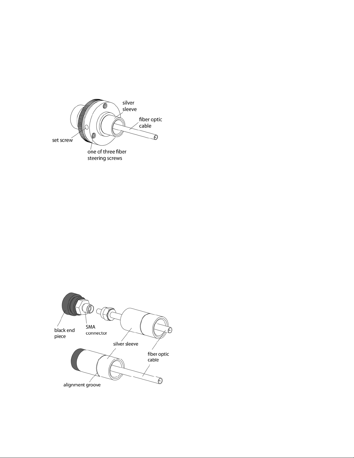
5.Now,unscrewthesilversleevefromtheblackendpiecerevealingtheSMAconnector
(Figure4).
6.Slidethesilversleeveovertheendofthefiberopticconnectorandcable,leavingthe
threadedendtowardtheendofthecable.
7.AttachthefiberopticcabletotheSMAconnector.
8.Holdingtheblackendpiece,screwthesilversleevebackintoplace.
9.InserttheSMAconnectorandsilversleeveintotheholeintheopticalassembly.Forafirst
adjustment,inserttheassemblyuntilthealignmentgrooveisevenwiththefaceofthelens
assembly.Later,youcanoptimizethesignalintensitybyslidingtheSMAconnectorand
silversleeveindeeper.
D.SoftwareInstallation
NOTE:IFYOUPURCHASEDTHET‐AppPROGRAM,DONOTPLUGINTHEUSBCABLEUNTILTHE
SOFTWAREISLOADED!IFYOUDO,WINDOWSMAYAUTOMATICALLYINSTALLANINCORRECT
DRIVERTHATWILLBEDIFFICULTTOREMOVE.
1.IfyoupurchasedtheT‐Appprogramforexternalcontroloftheturret 6,inserttheCDinto
thedrive.Iftheinstallationdoesnotstartautomatically,locatetheSETUP.exefileintheroot
directoryandrunit.Theinstallationprocessstartswithasmallblackwindowthatisshown
duringinstallationofthedriversneededtocontroltheturret 6throughaUSBconnection.
Thiswindowwillthenbereplacedbythesoftwareinstallationwindow.Followtheonscreen
promptstocompletetheinstallation.
2.Connecttheturret 6toyourcomputerusingtheUSBcableprovided.TheNewHardware
installationprocesswillbeginautomaticallyandtakeafewmomentstofinish.
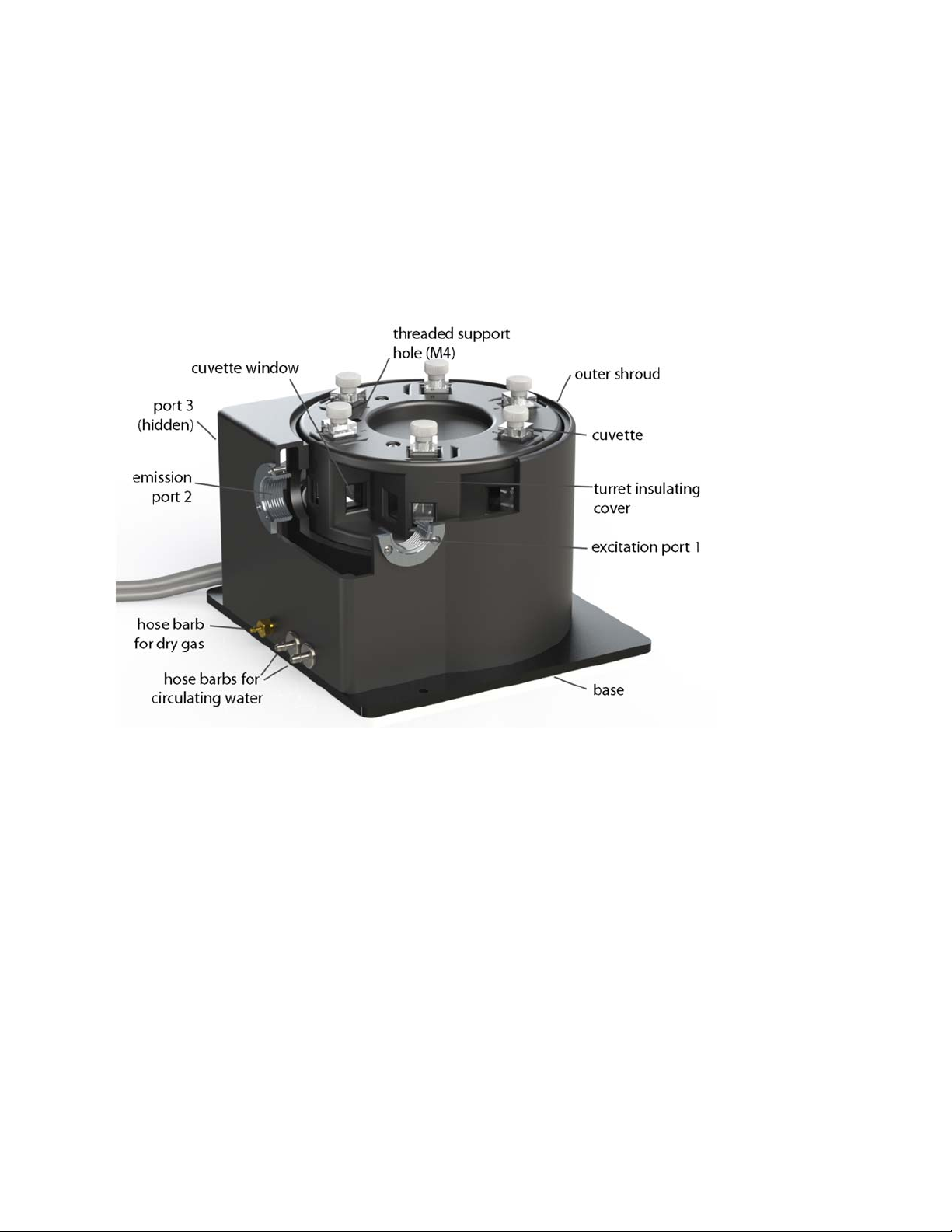
E.SystemOperation
1. Useliquidsamplesinstandard1x1‐cmsquarecuvettesandplacethecuvettesintheturret
6.
2. Placeamagneticstirbarineachcuvette.
3. Ifyouwishtomonitorthetemperatureinsideacuvette,plugastandardSeries400orSeries
500thermistorprobe(notprovided)intothe¼‐inchphonejacklabeled“probe”intheback
paneloftheTC1.Placetheendoftheprobeinaregionofthesolution,whereitwillnot
occludethespectrometerlightbeam.
4. TurnontheTC1controllerusingtheswitchonthebackpanel.

8
MenuButton
5. Thecontrollerdisplaybeginsonthe
Start
page.UsetheleftorrightarrowsontheMenu
Buttontocyclethroughthefivepagesofoptions.Onthe
SetPosition
pageusethetopand
bottomarrowstochooseaposition,sayposition5.Presssetandtheturretwillrotateto
thispositionandthemenuwillreturntothe
Start
page.Tosetatemperature,gotothe
Set
Temperature
pageandusetheupanddownarrowstosetatargettemperature,say37.0
°C.Press
SET
toinitiatetemperaturecontrol.Thetemperaturewillriseandstabilize.The
menuwillthenadvancetothe
SetStirrer
page.Usetheupanddownarrowstosetaspeed,
say1200rpm,andpress
SET
tostartthestirrer.
6. Whentemperaturecontrolisrunningandthe
Start
pageisbeingdisplayed,press
SET
to
turnofftemperaturecontrol.
7. Aftermeasurementsarecompleted,turnoffpoweronthebackoftheTC1controllerand
turnoffthewatersource.
F.UsingtheMenuButton
Usetherightandleftarrowstocyclethroughfivepages:
–Display–SetPosition–SetTemperature–SetStirring–SetRamping–
Display:
ThismainpageshowstheactualcuvetteHoldertemperature,theTargettemperatureanda
Probetemperature(ifaprobeispresent).Thepagewillalsoshowthecurrentturretposition.After
afewsecondsofinactivity,allotherpageswillswitchbacktothe
Display
page.
Whenseekingatemperature,thegreenledonthefrontpanelwillflashslowly.Whenithaslocked
ontoanewtargettemperature,thegreenledwillremainlit.Arapidlyflashingredledusuallymeans
alooseelectricalcableorinadequatewaterflowforthePeltierunit.
Holder = 37.0 °C
Target = 37.0 °C
Probe = 36.9 °C
Current Position = 5

9
SetPosition:Torotatetheturret6,usetheupanddownarrowstochoosethenewpositionand
pressSET.ThecontrollerwillreturntotheDisplaypage.
SetTemperature:TosettheTargettemperature,usetheupanddownarrows.PressSETtoretain
thisnewTargetandinitiatetemperaturecontrol.
SetStirring:Toturnonmagneticstirring,usetheupanddownarrowstochooseanapproximate
stirringspeedbetween1and2500rpm.PressSETtoturnonstirringatthisspeed.
SetRamping:Toperformaramp,settheRampingrateusingtheupanddownarrows,andpress
SET.Withrampingset,turningontemperaturecontrolwillgeneratealinearramptothetarget
temperature.Whenthesampleholderreachesthetargettemperature,therampratewillbeset
backto0°/minute.
Thefastestpossiblerampisdeterminedbyhowfastthecuvetteholdercouldreachthetarget
temperaturewithoutramping.Ifyouattempttoramptooquickly,especiallyathighandlow
temperatureextremes,youwillobtainanonlinearramp.Theslowestrampthatmaybesetonthis
pageis0.01°C/minute.(Ifneeded,muchslowerrampsmaybesetthroughsoftwarecommands.)
Set Ramping
Ramp = 0.55 °/min
Current = 0 °/min
Set Stirring
Stir Speed = 1200rpm
Current = 0rpm
Set Temperature
Target = 37.0 °C
Current= 20.0 °C
Set Position
Position = 5
Current Position = 1

10
2.FEATURESOFTHEturret6
A.GeneralDescription
Theturret 6hasarotating,temperature‐controlled,metalcuvettetowerwhichholdsuptosix
cuvettes.Aninsulatingcoverofurethaneplasticenclosesthecuvettetower,providingthermal
insulation.Afloorisattachedtothebottomofthetower,andtherotatingbodyoftheholder
containsaPeltierelementsandwichedbetweenthisfloorandabrassheatexchanger.Waterflows
throughtheheatexchangertodrawoffheatgeneratedwhenthetemperateofthecuvettetoweris
lowered.
Figure5.turret 6 withasectioncutawaytoshowtheopticaccesstooneofthecuvettes
Aminiaturesteppingmotorresidesundereachcuvettetodriverotatingmagnet.Drygasentersa
1/16‐inchhosebarbonthefrontoftheinstrumentandiscarriedthroughamanifoldinthefloorof
theturrettosmallholesonthebottomofthe18cuvettewindows.Thisflowofgaswillkeepthe
windowsfreeofcondensationwhenworkingbelowthedewpointtemperature.Therotatingbodyis
mountedonalargeprecisionbearingandrotatedviagears,usingtheexternalVextasteppingmotor
(notvisibleinthisview).
TwowiresexitbelowtheVextasteppingmotor.Oneconductsthedrivecurrentsforthestepping
motorandPeltierunit.Theotherconductsthesensorlines.Thetwobrass1/8‐inchhosebarbsfor
waterprovideaccesstotheheatexchanger.A1/16‐inchbrasshosebarbisusedforthedrygas.
CAUTION:
Accidentlyattachingawaterlinetothedrygasbarbwillseverelydamagethe
instrument!Attachthelineswithcare.

11
B.Cuvettes
Theturret 6holdsstandard10x10mmcuvetteswithoutsidedimensionsof12.5x12.5mm.A
metalclipisusedtopusheachcuvetteintooneofthecornersofitsindividualspaceforreproducible
positioningandtofavortemperaturetransfer.Wallsoftheturretbodyarerelievedtoprevent
scratchingoftheopticalsurfacesofthecuvette.
Cuvettesshouldbe45mmortaller,otherwisetheywillbedifficulttorecoverfromthecuvette
holders.
C.Cuvettez‐Height
The“zheight”ofacuvetteisthedistancebetweenthebottomsurfaceofthecuvetteandthe
designedpositionfortheopticalcenterline,wheretheincidentbeamoflightstrikesthecuvette.
Thezheightforcuvettesintheturret6is15mm.
Figure6.Thezheightofatypicalmicrocuvette
D.CoolingWaterforthePeltier
ThePeltierelement(or“thermoelectriccooler”)isaheatpump.Whencooling,ittransfersheat
fromtheturretbodytoaheatexchanger;whenheating,electricalpolarityisreversedandit
transfersheatfromtheheatexchangertothetower.Whencooling,itisparticularlyimportantto
transferthisheatawayfromthePeltier.Thisisaccomplishedwithflowingwaterthroughtheheat
exchanger.
Asourceofwater(orothercoolingfluid)mustbeconnectedtothe⅛‐inchhosebarbsonthefrontof
theturret 6.ThiscanbedonewiththeBATH10,whichisprovidewiththeturret 6. The BATH10
consistsofasubmersibleaquariumpump,theappropriatefittingsforconnectingtubing,anda
plasticbucket.Connectthepumptotheturret 6,placeitinthebucketwithwater,andrunareturn
tubetothebucket.Youmayalsoprovidethecoolingwaterfromanothersource,suchasa
refrigeratedcoolingbathorevenatapforbriefuse.
Youwillneedaflowrateof100‐300ml/minute.Thisflowshouldrequireapressureofabout3‐5
psi(0.2‐0.3bar).Donotexceedaninputwaterpressureof25psi(1.7bar),asdamagemayoccur
insidetheturret 6.Theheatexchangerandhosebarbsarebrass,andthetubinginsidetheturret 6
issilicone.Besurethatanycirculatingfluidused,otherthanwater,willnotdegradethesematerials.
Thetemperatureoftheheatexchangerintheturret 6ismonitoredusingathermistor.Ifthe
temperatureexceeds60°C,thentemperaturecontrolisshutdowntopreventdamagetothePeltier

12
elementandthewarning,“checkcoolantflow,”displayedontheTC1temperaturecontroller.This
willhappenifthecirculatingfluidgetstoowarmand/orisrestrictedinflow.Theheatexchanger
temperaturemaybeaccessedbycomputerthroughtheRS232orUSBconnectionsonthebackof
theTC1TemperatureController(seeExternalcomputercontrolbelow).
Temperatureincreaseswillbefasterwhenroomtemperaturewaterisusedinthecirculator.
Temperaturedecreaseswillbefasterwhenicewaterisused.Onlywatershouldbecirculatedusing
theBATH10.Whenusingarefrigeratedbath,circulatingpre‐cooledfluids(suchas30%methanolor
dilutedethyleneglycol)atbelow0°Cwillpermitmeasurementsbelowthespecifiedtemperature
range.
E.DryGasPurging
Drygasflowsintotheturret 6viathe1/16‐inchbrasshosebarbontherearside.Thegaspasses
throughsmallchannelsinthebaseoftheturretbody,topartiallyequilibrateintemperature,before
passingupthroughsmallholesonboththeinsideandoutsidecuvettesurfaces.Aflowofdrygasto
preventcondensationisnecessaryanytimetheturret 6iscontrolledbelowthedewpoint
temperaturepresentontheinsideofthesamplecompartmentofthespectrometer.Forambientair,
thiswouldtypicallybeabout5°C.
F.ExternalTemperatureProbe
A¼‐inchphonejacklabeled“Probe”canbefoundonthebackpanelofTC1TemperatureController.
ThisjackwillaccepttheplugonastandardSeries400orSeries500thermistorprobe.Whenaprobe
ispluggedintothejack,theprobetemperatureispresentedonthedisplayoftheTC1.Placethe
probeinasampletomeasuretheactualtemperatureofthesample,whichwilllagintimefromthe
temperatureofthecuvettetower.
Wedonotselltheprobe,buttherearemanySeries400and500probesonthemarket.Quantum
Northwest’spreferredprobeistheYSI423availablefromColeParmer.TheYSI423isreasonably
resistanttoimmersionandrespondsrapidlytotemperaturechanges.Also,thefine,coiledwiresof
theYSI423conductverylittleambientheattothethermistorattheend.
ExcellentSeries500probescanbeobtainedwithdiameterslessthanamm,providingaccesstosmall
volumes.Adisadvantageoftheseprobesisthattheyarenotpre‐calibrated.
G.ExternalComputerControl
AllfunctionsmaybeaccessedeitherthroughaSerial(RS232)oraUSBlocatedonthebackofTC1
TemperatureController.YoumaywriteyourownprogramorpurchaseourapplicationprogramT‐
App.T‐Appwillplottemperaturesoftheprobe,cuvettetoweroreventhePeltierelementheat
exchangervstime.Itwillalsopermityoutosetuptemperatureramps.Ifyouwishtodoyourown
programming,pleaseseetheAppendixforcommunicationinstructionsandthesetoftext
commandsthatmaybeusedandresponsestothecommands.
H.DescriptionofLensSystems
Thet6‐QCLcollimatinglensisa6mmdiameter,18mmfocallength,fusedsilicalensthatcollects
lightfromthesourcefiberatanumericalapertureof0.22andfocusesa5mmdiametercollimated

13
0
0.5
1
1.5
2
2.5
200 300 400 500 600 700
% Reflectance
Wavelength
beamthroughthecuvetteatazheightof15mm.Asecondt6‐QCLreversestheprocessandfocuses
thecollimatedlightontoacollectionfiber.
Therearetwokindsofimaginglenssystems.Eachcontainsapair12.5mmdiameter,30mmfocal
length,plano‐convex,fusedsilicalenseswiththeirflatsidesoutward.Theexcitationlens(t6‐QIL/ex)
focusesanimageoftheendofthesourcefiberintothemiddleofthecuvettewithamagnificationof
2.7.Theemissionlens(t6‐QIL/em)focusesasmallregionoftheilluminatedvolumeinthecenterof
thecuvetteontotheendoftheemissioncollectionfiberusingamagnificationof1.0.
Themagnificationoftheexcitationlensrepresentsacompromiserequiredtobackthelensaway
fromthecuvettetopermittherotationoftheturret.Ifhighfluorescencesensitivityisrequired,we
recommendamoredirectcouplingofthesourcewiththecuvette,bypassingtheexcitationfiber.
Figure7.Broadbandanti‐reflection(AR)coatingusedonthestandardfusedsilicalenses.

14
3.ERRORCODES
Whenerrorsoccur,theline1ofthedisplaypresentsanerrorcode.Line3ofthedisplayidentifies
theerrorandline4ofthedisplaypresentspossiblesolutions.Themostcommoneventsthatcause
errorstobedisplayedareloosecablesorinadequatecoolantflow.Forerrorsnoteasilysolved,
pleasecontactusthroughourwebsite,www.qnw.com.
E5–celloutofrange
warnings:loosecable,sensorfailure
Thetemperaturecontrollerisnotreceivingareasonableresponsefromthesensoronthecuvette
tower.Eitherthesensorhasfailedoracableisnotmakingagoodconnection.
E6–celloutofrange
warnings:loosecable,checkcable
Thetemperaturecontrollerisnotreceivingreasonableresponsesfromeitherthecelltowerorheat
exchangersensors.Sinceitisveryunlikelyforbothtofail,probablyacableisloose.
E7–heatexchangererror
warnings:loosecable,sensorfailure
Thetemperaturecontrollerisnotreceivingareasonableresponsefromthesensorontheheat
exchanger.Eitherthesensorhasfailedoracableisnotmakingagoodconnection.
E8–inadequatecoolant
warnings:inadequatecoolant,watertemperature
Thesensorontheheatexchangerisreadingatemperatureabove60°C.Temperaturecontrolhas
beenshutdowntopreventdamagetothePeltierelement.Eitherthewaterwastoowarmorthe
rateofflowwasinadequatetodrawsufficientheatfromtheheatexchanger.

15
4.SPECIFICATIONSSUMMARY
temperaturerange‐20to+110°C
temperatureprecision ±0.02°C
cuvettesize(outsidedimensions)12.5x12.5mm
minimumcuvetteheight 30mm
cuvettezheight15mm
opticalportdimensions 12mmhighx10mmwide
magneticstirringspeed 1‐2500rpm

16
APPENDIX1.TEMPERATURESPECIFICATIONSFORTHETURRET6
EnochW.SmallandLouisJ.Libertini
26July2013
TemperatureRange:‐15°Cto+80°C
TheTC1TemperatureControllercansettemperaturesbetween‐40°Cand110°C.Undernormal
conditions,asusedinsideaspectrophotometer,theturret6willachievetemperaturesintherange
of‐15°Cand80°Cusingroomtemperaturewater(~22°C).Somewhatlowertemperaturescanbe
obtainedbytheuseoficedwater.Temperaturesabove80canusuallybeattainedbyusingwarm
water(recommended).Insomecaseshighertemperaturesmayrequireoperationwithoutcoolant
flow,butspecialproceduresarerequired.
Aninputconnectionforpurgingwithdrygasisprovided.
TemperaturePrecision:±0.02°C
Temperatureprecisionistheaveragedeviationfromthesettemperatureoftemperaturereadings
returnedfromthetemperature‐controlledturret6forsettemperaturesbetween‐15°Cand+110
°C.Thus,itisameasureoftheabilityofthecuvetteholdertoholdaconstanttemperature.
Theprecisionofthetemperatureactuallyheldinthesolutionshouldbeevenbetterthanthe
precisionforthecuvetteholder.Unfortunately,wehavenocurrentmeansofmeasuringit.
Table1.Averagedeviationfromthesettemperaturevssettemperaturefor50points.
Settemperature‐150.020.040.060.080.0100110
Averagedeviation0.00460.0640.0020.00840.0080.00660.00820.0116
TemperatureAccuracy:±0.25°Covertherangeof‐20°Cto+110°C.
TemperatureAccuracyindicateshowwelltheTC1controllerdisplay,aftercalibration,compares
withtheactualtemperatureofthesampleholdermeasuredusingaNIST‐traceableRTDtemperature
probe(probeaccuracy±0.03°Cfrom‐99.9°Cto+99.9°C)insertedinthemetalblockofthecuvette
holder.

17
Figure1.AnNIST‐traceableRTDthermometer(accuracy±0.03°Cfrom‐99.9°Cto+99.9°C)was
insertedinthebodyofthecuvetteholderandthetemperaturereadings(yaxis)comparedtothe
valuesetbytheTC1temperaturecontroller(xaxis).Datapointsshownasredsquaresareresults
wereobtainedwiththetemperaturedecreasing;thebluediamondsindicateresultsobtainedwith
thetemperaturedecreasing.
TemperatureReproducibility:betterthan±0.15°Covertherangeof0°Cto80°C
Temperaturereproducibilityisameasureoftheabilityofthetemperaturetoreturntoanoriginal
value(SeeFigure1.).Itaccountsfordifferencesdependingonthedirectionoftemperaturechange
anddifferencesfromdaytoday.ReproducibilityismeasuredusingaNIST‐traceableRTD
temperatureprobeinsertedinthemetalblockofthecuvetteholder.
ExampleofTemperaturePerformance
Figure2.turret6cuvetteholdertemperatureandsampletemperature(red,measuredwitha
thermistorprobeconnectedtothet2)asthetargettemperaturesettingwasprogressedthrough
20.0°C,50.0°C,0.0°C,‐15.0°C,80.0°Cand20.0°Cdegrees.
time (min)
160140120100806040200
temperature (°C)
80
70
60
50
40
30
20
10
0
-10

18
TypicalTemperatureEquilibrationData
ATurretwasequilibratedatonetemperatureandthenthetargettemperaturewaschangedtoa
higherorlowervalue.
Table2.Timerequiredforcuvetteholdertemperaturechanges.Threetimeareshown:thetime
requiredtogetwithin1°C,thetimetogetwithinthelockontemperatureof±0.05°Cfromthe
targetandthefinaltimeindicatingthattheTC1indicatesthetemperatureisstable.
Temperaturerange(°C)20to8080to11080to2020to‐15
CirculatingwaterT(°C/min)21none21Iced
Minutestogetwithin1°C(min)13389.315
Minutestolockontemperature(min)164213.320
Minutestolockonindicatorlight(min)18541825

19
APPENDIX2.SERIALCOMMUNICATIONSFORTHETC1
TEMPERATURECONTROLLER
7/26/2013
Thisdocumentprovidestheserialcommunicationsprotocolsforversion1.0ofthefirmwareonthe
TC1familyofcontrollers:
TC1/t2–forthet2,singletemperaturecontroller
TC1/t2x2–forthet2x2,dualtemperaturecontrollerforsampleandreference
TC1/turret6–fortheturret6,6‐positionturret
TheversionnumberandtheID(seebelow)areshownbrieflyonthedisplaywhenthetemperature
controlleristurnedon.
All functions of the temperature controller can be managed from a computer, using the command set
described below. If you purchased your unit as a component of a spectrometer from certain
manufacturers, this feature may be implemented through traditional RS232 serial connectors on the
computer or the spectrometer and on the controller. In this case they will be connected by a standard
15-pin serial extension cable (male connector on one end and female on the other). No driver
installation should be needed.
Otherwise the serial linkage will be established through a USB connection between the computer and
the controller. In this case the controller includes electronics which convert the USB connection to a
serial communications port. However, for the port to be available to programs on the computer it will
be necessary to load driver software. It is important that the driver software be loaded before
connecting a USB cable between the controller and the computer. Contact Quantum Northwest for
further information.
Quantum Northwest can provide a control program written specifically for control of all functions of the
temperature controller. Ask for program T-App.
In programming for the TC 1 controller, one must adhere to the conventional notation: 8/N/1.
Baud: 19200
Data Bits: 8
Parity: None
Stop Bit: 1
Flow Control: None
Formanyofthecommandslistedbelowthecontrollerreturnsinformationinresponsetothe
command.Allcommandsandresponsesaredelineatedbyleftandrightsquarebrackets([]).Any
textsenttothecontrollernotenclosedwithinbracketswillbeignored.Inthisdocumentanellipsis
(……)isusedtodistinguishresponsesfromcommands.
[command] Purposeofthecommand(senttothecontroller).
......[response] Meaningoftheresponse(receivedfromthecontroller).
1. Identify
[F1 ID ?] WhatistheIDnumberofthesampleholderbeingcontrolled?
......[F1 ID 14] Sampleholderisat2orothersinglecuvettesampleholder.

20
AssignedIdentities:
ID=00–specialtysampleholder(seecommandclass14)
14‐t2
24‐t2x2
34–reservedforturretorlinearmulti‐sampleholder
2. ControllerFirmwareVersion
[F1 VN ?] Whatistheversionnumberofthecontrollerfirmware?
......[F1 VN 1.00] Thecontrollerisoperatingfirmwareversionnumber1.00.
3. Stirrer
[F1 MS ?] Whatisthemaximumstirrerspeed?
......[F1 MS 2500] Themaximumstirrerspeedis2500rpm.
[F1 LS ?] Whatistheloweststirrerspeed?
......[F1 MS 300] Theloweststirrerspeedis300rpm.
[F1 SS S 1000] Setstirrerspeedto1000rpm.
[F1 SS S 0] Turnstirreroffandsetthespeedtozero.
[F1 SS +] Turnstirreronandsetittothemostrecentnon‐zerostirrerspeedsetting.
[F1 SS -] Turnstirreroff.
[F1 SS ?] Whatisthecurrentstirrerspeedsetting?
......[F1 SS 1000] Stirrerspeedsettingis1000rpm.
4. TemperatureControl
[F1 TC +] Turntemperaturecontrolon.
[F1 TC -] Turntemperaturecontroloff.
5. TargetTemperature
[F1 TT S 23.10] Settargettemperatureto23.10ºC.
[F1 TT ?] Whatisthecurrenttargettemperature?
......[F1 TT 71.32] Targettemperatureis71.32ºC.
[F1 TT +] Turnonautomaticreportingofmanualchangestothetargettemperature.
[F1 TT -] Turnoffautomaticreportingofmanualchangestothetargettemperature.
[F1 MT ?]Whatisthemaximumtargettemperatureallowed?
......[F1 MT 110]Themaximumtargettemperatureallowedis110ºC.
[F1 LT ?]Whatisthelowesttargettemperatureallowed?
......[F1 LT -30]Thelowesttargettemperatureallowedis‐30ºC.
Table of contents
Other Quantum Laboratory Equipment manuals
Popular Laboratory Equipment manuals by other brands

Thermo Scientific
Thermo Scientific Thermo Scientific SL16R instruction manual

Delta UV
Delta UV EA Series Installation & maintenance manual

Branson
Branson Sonifier SLPt user manual

IKA
IKA RV 10 control operating instructions

Apex Digital
Apex Digital Sturdy SA-300VMA-R instruction manual

Selecta
Selecta CENCOM 2 instruction manual