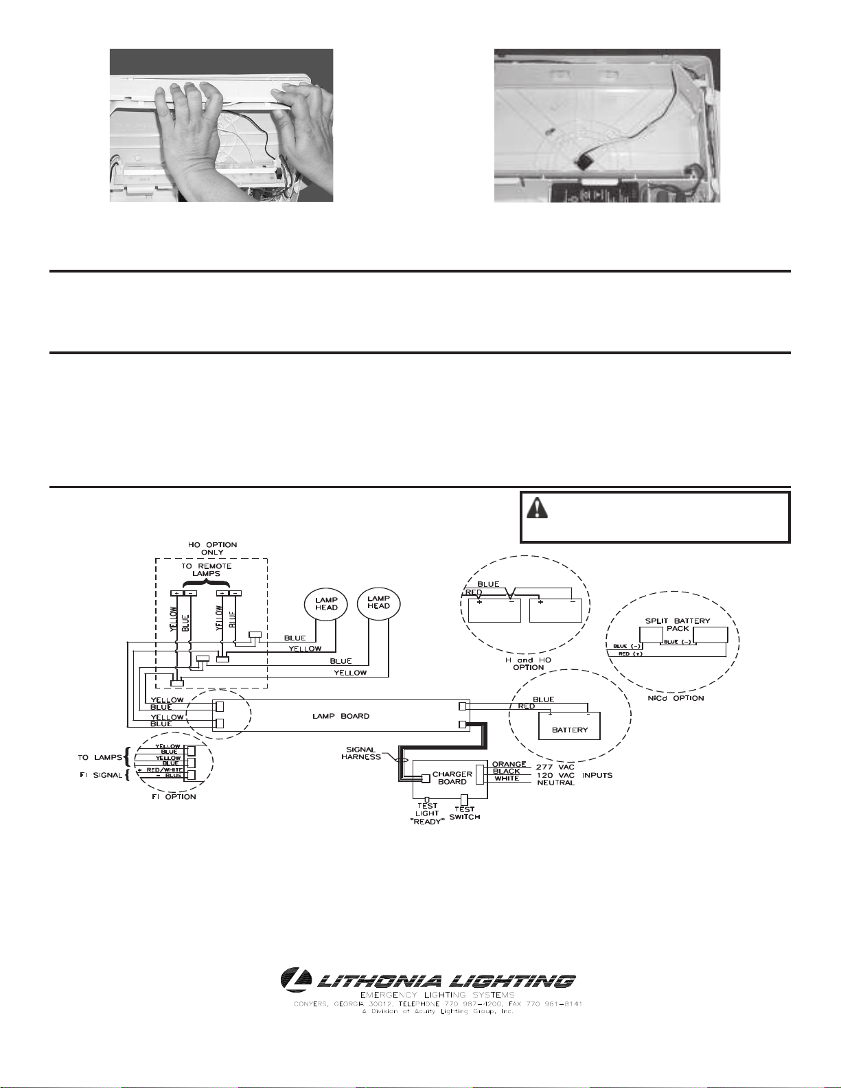
Quantum LHQM User manual

MODEL LHQM
EXIT/UNIT COMBINATION
US Patent No. 5,526,251; 5,646,502; 6,142,648; D379,373; 5,611,163; D484,272; D473,672
Canadian Patent No. 80,141 & 2,180,495
IMPORTANT SAFEGUARDS
READ AND FOLLOW ALL SAFETY INSTRUCTIONS
SAVE THESE INSTRUCTIONS AND DELIVER TO OWNER AFTER INSTALLATION
WARNING:FAILURE TO FOLLOW THESE INSTRUCTIONS AND WARNINGS MAYRESULTIN DEATH, SERIOUS INJURY
OR SIGNIFICANT PROPERTY DAMAGE – For your protection, read and follow these warnings and instructions carefully before
installing or maintaining this equipment. These instructions do not attempt to cover all installation and maintenance situations. If you do
not understand these instructions or additional information is required, contact Lithonia Lighting or your local Lithonia Lighting distributor.
WARNING:RISK OF ELECTRIC SHOCK – NEVER CONNECT TO, DISCONNECT FROM OR SERVICE WHILE EQUIPMENT IS
ENERGIZED.
WARNING:RISK OF FIRE – Lamps are hot. Keep combustibles material away from hot parts. Observe lamp manufacturer’s
warnings, recommendations and restrictions on lamp operation and maintenance. Make sure lamps are correctly installed.
WARNING:DO NOT USE ABRASIVE MATERIALS, OR OTHER SOLVENTS. USE OF THESE SUBSTANCES MAYDAMAGE
FIXTURE, WHICH MAY RESULT IN PERSONAL INJURY.
WARNING:RISK OF PERSONAL INJURY– This product may have sharp edges. Wear gloves to prevent cuts or abrasions when
removing from carton, handling, installing and maintaining this product. (WHERE APPLICABLE)
•Before wiring to power supply, turn off electricity at fuse or circuit breaker.
•Disconnect A.C. power and unplug battery before servicing.
•Consult your local building code for approved wiring and installation.
•Do not use outdoors.
•Do not let power supply cord touch hot surfaces.
•Do not mount near gas or electric heater.
•Do not install a damaged fixture.
•This product must be installed in accordance with the applicable installation codes and ordinances.
•Proper grounding is required to ensure personal safety. (WHERE APPLICABLE)
•All service shall be performed by qualified service personnel. This product must be installed and maintained in accordance with the
applicable installation codes by a person familiar with the construction and operation of the product and the hazards involved.
•Equipment should be mounted in locations and at heights where it will not readily be subjected to tampering by unauthorized personnel.
•The use of accessory equipment not recommended by the manufacturer may cause an unsafe condition.
•Do not use this equipment for other than intended use.
•Halogen cycle lamps operate at high temperatures. Do not store or place flammable materials near lamp.
•Use caution when servicing batteries. Battery acid can cause burns to skin and eyes. If acid is spilled on skin or eyes, flush acid with fresh
water and contact a physician immediately.
CAUTION:Halogen cycle lamp(s) may be used in this fixture. To avoid shattering, do not operate lamp in excess of rated voltage.
Protect lamp against abrasions and scratches and against liquids when lamp is operating. Dispose of lamps with care. Halogen lamps operate
at high temperatures. Do not store or place flammable materials near lamps.
SAVE THESE INSTRUCTIONS

Page 2
GENERAL INFORMATION
SHOWN WITH LEAD ACID BATTERY
To Remove Directional chevrons-
Remove colored panel and push chevron out for
desired configuration.
DC Connection-
Connect battery to lamp board
AFTER AC power can be continuously provided to exit.
To Remove Face Plate-
Press in snaps at bottom or top of housing to separate
face plate from housing.
Remove and Relocate Lamp Mount Assembly
Remove face plate and back plate.
Disconnect lamp harness from lamp board.
Press four snaps (two each side) to release lamp
mount assembly from housing. Relocate to top of
housing and resnap into place. Connect lamp harness
to lamp board.
To Remove Lens and Change Lamps-
Release lens bylifting outward and over button with
thumb. Replace lamp with an identical lamp.
To Remove Back Plate-
Press in snaps at bottom or top of housing. Then
release latches Aand B from the inside of housing.
To Remove Canopy-
Rotate cam locking pin level with housing and remove
from hooks. Squeeze snaps and pull housing free.
A
B
C
D
E
F
G

Page 3
1. Remove face place. Connect jumper leads
(provided) to AC input leads in j-box. Fasten j-box
bracket to j-box.
2. Fasten canopy to j-box bracket.
3. Remove hole plug and dress leads through housing
wire channel. Snap exit housing onto canopy.
4. Lay cam locking pin between canopy posts and
snap into retaining hooks. Rotate cam locking pin
up to lock into place.
Back Mount-
2. Remove necessary knockouts and fasten back
plate to j-box.
1. Remove faceplate. Connect installation supply leads
(provided) to AC input leads in j-box. Remove face
plate and back plate from housing.
5. In upper right corner of housing wire channel
connect input leads using pushnuts and jumper
wire provided to route wires to j-box. Connect
battery and snap face plate onto housing. Remote
lamp option: Connect remote lamps to yellow and
blue wires using pushnuts and jumper wire
provided to route wires to j-box.
Top Mount -
Use only Flexible Conduit
with this unit.
Note: AllowBatterytocharge
24 hours before initial testing
and 168 hours for full charge.

EMCSA00673
REV. H
WIRING DIAGRAM
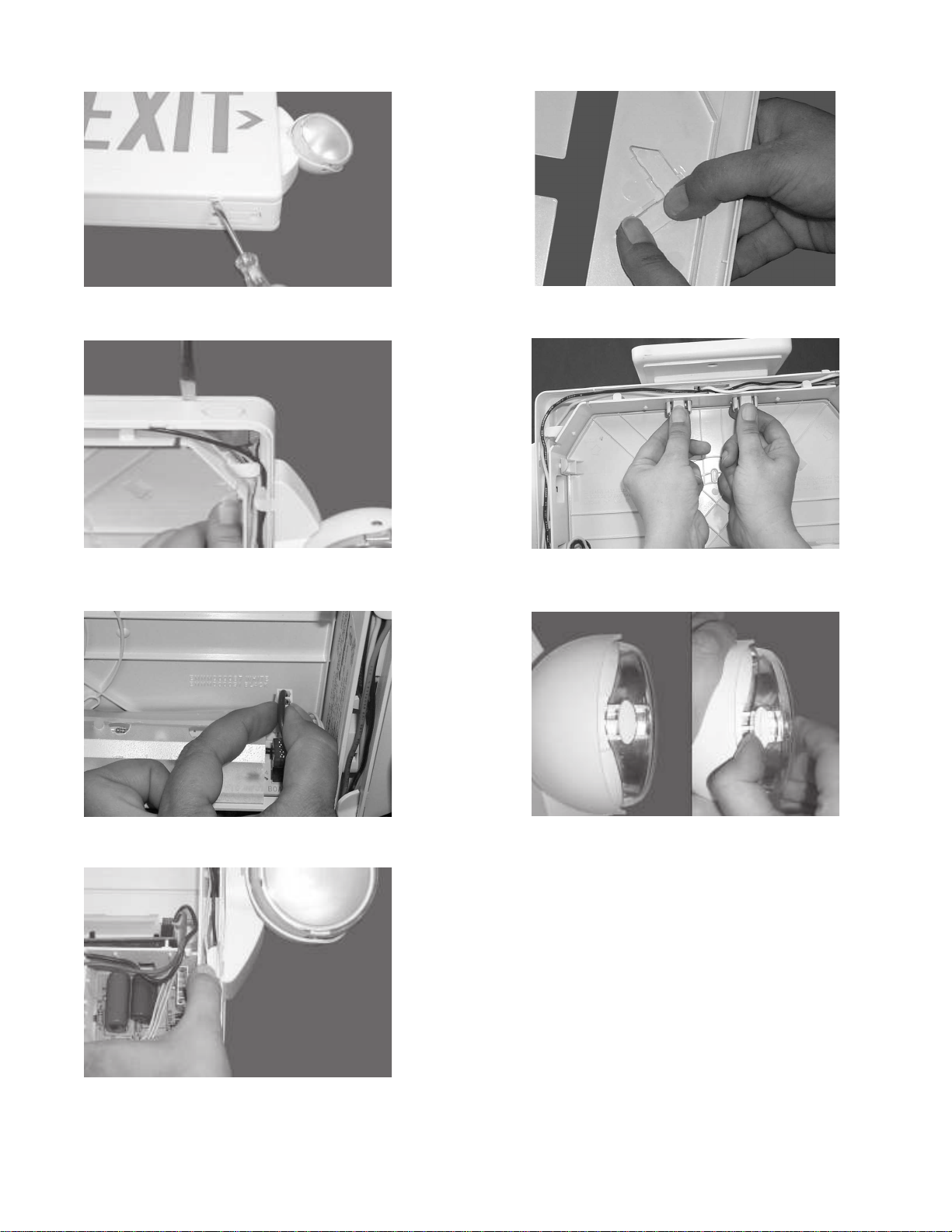
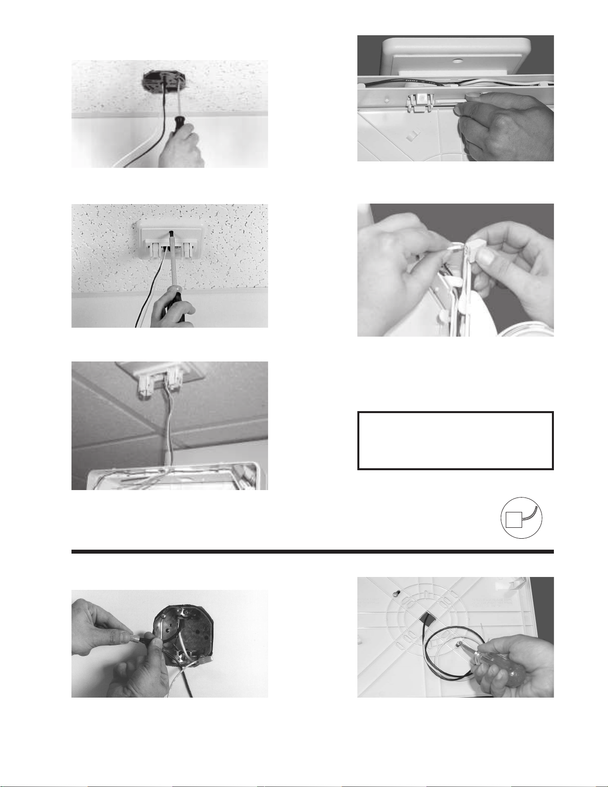
3. Snap housing to back plate. 4. Route wires through upper wireway. In upper right corner of hous-
ing wire channel, trim and connect input leads using pushnuts and
jumper wire provided to route wires to j-box. Connect battery and
snap face plate onto housing. Remote lamp option: Connect re-
mote lamps to yellow and blue wires using pushnuts and jumper
wire provided to route wires to j-box.
power supply harness from charger board. From backside of
charger board lift snap holding charger board and remove board.
Insert new board; reconnect wiring harnesses and replace charger
board cover.
E. Lamp board Replacement: Disconnect battery, signal harness,
and lamp harnesses from lamp board. Pinch snaps and lift lamp
board. Insert new lamp board, reconnect lamp harnesses, signal
harness, and battery.
INSPECTION AND MAINTENANCE
NOTE: Emergency lighting systems should be tested in accordance with NFPA101 requirements, to ensure that all components are operational.
Note: Cap all unused leads separately.CAUTION: Damage to battery will occur if
battery is connected to charger board for
longer than 3 days time without AC power
provided.
A. Normal Operation: LED lamp strip and green “Ready” light will be
illuminated when AC Power is supplied.
B. To Test: Push "Test" switch; DC emergency lamps will come on.
LED lamp strip will remain on.
C. Battery Replacement: Push tab away from battery while lifting
out battery. Disconnect leads from terminals.
Page 4
Directions For End-Mounting
A. Remove the back plate (refer to photo B)
B. Remove the left lamp mount assembly. Discard unused lamphead
or relocate to top mount (refer to photo D,this photo shows the
right lamp head but the instructions are the same).
C. The face plate and back plate may have to be reversed for correct
view orientation.
D. Use top mounting instructions to attach to junction box.
D. Charger Board Replacement: Remove face plate and back plate.
Remove charger board cover. Disconnect signal harness and
Important Battery Information:
Batteries are perishable items. For best results, it is recommended that the battery receive an initial charge within the first 18 months of the
manufacture date of the fixture. The mfg date can be found on the outside of the unit packaging and on the UL label as part of the Date Code/
Series. Note: First two digits in the date code will represent the year and the second two digits will represent the month. Batteries beyond the initial
charge recommendation time frame can often times be returned to full capacity by fully charging the battery shortly after installation. If the battery
will not fully charge after the initial charge, replacing the battery with a fresh battery will resolve the issue.Batteries are perishable items. For best
results, it is recommended that the battery receive an initial charge within the first 18 months of the manufacture date of the fixture. The mfg date
can be found on the outside of the unit packaging and on the UL label as part of the Date Code/Series. Note: First two digits in the date code will
represent the year and the second two digits will represent the month. Batteries beyond the initial charge recommendation time frame can often
times be returned to full capacity by fully charging the battery shortly after installation. If the battery will not fully charge after the initial charge,
replacing the battery with a fresh battery will resolve the issue.
Other Quantum Lighting Equipment manuals
Popular Lighting Equipment manuals by other brands

Prime Design
Prime Design Baselight 420X user manual

Lightolier
Lightolier ProSpec 26890 specification

Hunter
Hunter 27186 instructions

Federal Signal Corporation
Federal Signal Corporation Electraray 225 instruction manual

LumaPro
LumaPro 30UH85 operating instructions

Federal Signal Corporation
Federal Signal Corporation Valor VALR44 Installation maintenance and service manual