Quell Q1300 User guide

Smoke alarm
Installerʼs Manual
240V Interconnectable Main Operated Alarm
For models: Q1300
Thank you for purchasing Quell 240V hard-wired photoelectric
smoke alarm. Please read through our guide in full.
Chubb Fire & Security Pty Limited recommends for maximum
protection that both ionisation and photo-electric (optical) smoke
alarms be installed. Ionisation sensing alarms may detect
invisible fire particles (associated with fast flaming fires) sooner
than photoelectric alarms. Photoelectric sensing alarms may
detect visible fire particles (associated with slow smouldering
fires) sooner than ionisation alarms. Home fires develop in
different ways and are often unpredictable.
Electrical rating 240V AC,
50Hz 80mA max per alarm
(maximum 80mA for originating unit
with 24 Devices interconnected).
Chubb Fire & Security Pty Limited
149-155 Milton Street, Ashfield NSW 2131, Australia
www.quell.com.au
THE OWNER’S MANUAL SHOULD BE LEFT IN A SAFE PLACE
FOR THE PROPERTY OWNER.
P/N:130413, 132819
1385-7210-02
1385-7210-02(130413)_Installer.qxd:_ 2013.1

Contents
Section 1. Installation Instructions ................................................1
Section 2. Recommended Locations ............................................2
Section 3. Locations to be Avoided...............................................4
Section 4. Installing Alarm.............................................................6
Section 5. Interconnecting.............................................................7
Section 6. Initial Testing and Checking of Alarm...........................7
Section 7. L.E.D. Status.................................................................8
Section 8. Maintenance.................................................................8
Section 9. Battery Replacement....................................................8
Section10. Repair/Servicing.........................................................10
Section11. Limitations of Smoke Alarms......................................10
Section12. Troubleshooting..........................................................12
Section13. Warranty & Contact Details........................................13
1385-7210-02(130413)_Installer.qxd:_ 2013.1

1
1. Installation Instructions
This alarm is designed for installation by a qualified (licensed)
electrician, in accordance with current Building Code of Australia (BCA)
Regulations and to any other local or building codes that may apply.
• Read these instructions thoroughly before proceeding.
Peopleʼs lives depend on it.
•
This manual is supplied for your guidance and should not be left with
the property
owner. This is for use by qualified licensed electricians.
• AC alarms must be powered by a constant 240V AC, 50Hz supply that
is not controlled by any form of switch.
Grade ‘D’ – AC with secondary power e.g. Alkaline battery/rechargeable
cells. Recommended to connect to dedicated circuit that is
separately electrically protected. This helps minimise Electro-Magnetic
interference (EMI) on alarm interconnect line from Compact
Fluorescent Light (CFL's),dimmers,
low voltage (LV)
transformers etc.
Only interconnect to the identical brand of smoke alarm. Do not
connect to any other brand of alarm/auxilary device unless approved
by Chubb.
The Earth terminal is provided to facilltate wiring termination of the
Earth wire,which plays no part in the safety protection of the alarm.
• When testing the alarm, stand back so your hearing is not damaged by
the 85dB sounder.
In new build or refurb projects, protect the alarm with a dust cap to
prevent insects or dust contamination by following trades. The property
owner or other responsible person must be advised to remove them for
the alarms to operate correctly (ideally, fit alarms at latest stage
possible onto pre-installed mounting base).
Danger – electrical shock hazard!
Never restore power supply until all alarms are completely installed.
Doing so before hand can cause serious injury.
Do not install in a dripping, water splashing, very humid area.
WARNING: This alarm cannot be operated from power derived from a
square wave or modified sine wave inverter. These types of inverters
are sometimes used to supply power to the structure in off grid
installations, such as solar or wind derived power sources. These
power sources produce high peak voltages that will damage the alarm.
Do NOT subject the alarm circuit to insulation resistance testing with
the alarm base units connected. Failing to do so will cause damage
outside the terms of the guarantee provisions.
1385-7210-02(130413)_Installer.qxd:_ 2013.1

2
2.Recommended Locations
• Install the first alarm in the immediate area of the bedrooms. Install
additional alarms to monitor the exit path as the bedrooms are usually
farthest from the exit. If more than one sleeping area exists, install additional
alarms in each sleeping area (Image 1A).
• Install additional alarms to protect any stairway as stairways act like
chimneys for smoke and heat.
• Install at least one alarm on every floor level (Image 1B).
• Install an alarm in every bedroom where a smoker sleeps.
• Install an alarm in every room where large electrical appliances are operated
(i.e. portable heaters or humidifiers).
• Install an alarm in every room where someone sleeps with the door closed.
The closed door may prevent the alarm from waking the sleeper.
• Smoke, heat and combustion products rise to the ceiling and spread
horizontally. Mounting the smoke alarm on the ceiling in the centre of the
room places it closest to all points in the room. Ceiling mounting is preferred
in ordinary residential construction.
• When mounting an alarm on the ceiling, locate it at a minimum of 30cm (12")
from the side wall.
• When mounting the alarm on the wall, use an interior wall with the top edge
of the alarm at a minimum of 10cm (4") and a maximum of 30cm (12'') below
the ceiling.
• Put smoke alarms at both ends of a bedroom hallway or large room if the
hallway or room is more than 9.1m (30 feet) long.
1385-7210-02(130413)_Installer.qxd:_ 2013.1

3
Smoke Alarms for Minimum Protection
Smoke Alarms for Additional Protection
Ionization Type Smoke Alarms with
“Hush” Control or Photoelectric Type
BEDROOM
BASEMENT
KITCHEN
HALL BEDROOM
LIVING
ROOM
IMAGE 1A IMAGE 1B
SINGLE FLOOR PLAN MULTIPLE FLOOR PLAN
•Install smoke alarms on sloped, peaked or cathedral ceilings
between 500 and 1500mm from the highest point of the ceiling.
Smoke alarms in rooms with ceiling slopes greater than 1 m in 8 m
horizontally should be located on the high side of the room (See
Image 2B).
IMAGE 1C
BEDROOM
FAMILY ROOM
WORKSHOPBASEMENT
KITCHEN
HALL
GARAGE
MASTER
BEDROOM
FIRE
EXTINGUISHERS
SMOKE
ALARMS
FIRE BLANKET
TOTAL HOME PROTECTION
BEDROOM KITCHEN
LIVING ROOM
BEDROOM
BEDROOM
BEDROOM
1385-7210-02(130413)_Installer.qxd:_ 2013.1

4
3. Locations to be Avoided
3A • Do not install within 0.9 m (3 ft) of the following: The door to a kitchen, or
a bathroom that contains a tub or shower, forced air supply ducts used
for heating or cooling, ceiling or whole house ventilating fans, or other
high air-flow areas.
• Do not place the alarm where curtains or other objects will block the
sensor. Smoke must be able to reach the sensor to accurately detect
conditions.
• Install at least 30cm (12 in) away from fluorescent lights as electronic
noise may cause nuisance alarms.
• Keep out of insect infested areas. Avoid excessively dusty, dirty or greasy
areas. Dust particles may cause nuisance alarms or failure to alarm.
• Extreme temperatures may effect the sensitivity of the alarm. Do not
install in areas where the temperature is colder than 5°C or hotter than
45°C, such as garages and unfinished attics.
• Do not install in areas where the relative humidity (RH) is greater than
85%. Very humid areas, with moisture or steam, can cause nuisance
alarms.
• Avoid placing smoke alarms in kitchen areas. Normal cooking may cause
nuisance alarms. If a kitchen alarm is desired, it should have an alarm
silencer feature or be a photoelectric type.
• Do not place in the garage. Particles of combustion are present when
you start your automobile.
• Smoke alarms are not to be used with detector guards unless the
combination (alarm and guard) has been evaluated and found suitable
for that purpose.
• In dead air spaces such as the peak of an “A” frame ceiling. “Dead Air” at
the top may prevent smoke from reaching the alarm in time to provide
early warning. Refer to images 2A and 2B.
Timing of Installing/Decorating
3B • Install the base plate (and surface pattress if used) at 1st fix.
•Do not install alarm until following trades have finished e.g.
plasterers/painters/carpet fitters etc..
•Do not install alarms until property has stabilized at a habitable
environment to avoid alarm contamination.
•
Dust and other contaminants e.g. paint fumes, will enter the alarm causing
possible
nuisance alarms and damage the sensitive components within.
• Never plug in or remove cabling when circuit is live as you could short
circuit it and invalidate the guarantee.
Painting
3C • Never paint the alarm.
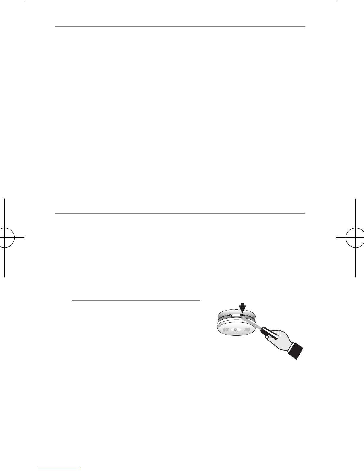
• During redecoration, all alarms should be covered with the supplied
dust cover or a plastic bag to prevent contamination by fumes.
(These can permanently damage the alarm). Do not uncover until
the surrounding paintwork is thoroughly dried.
• Alarm cannot operate if covered.
1385-7210-02(130413)_Installer.qxd:_ 2013.1

5
IMAGE 2A
IMAGE 2B
CEILING
30 cm (12 in)
MINIMUM
10 cm (4 in)
MINIMUM
30 cm (12 in)
MAXIMUM
SIDE WALL
BEST
PLACEMENT
ACCEPTABLE
PLACEMENT
DO NOT INSTALL
DEAD AIR
NOT IN
THIS AREA
ANYWHERE IN THIS
AREA
NOT IN
THIS AREA
ANYWHERE IN THIS
AREA
PEAK CEILING
SLOPED CEILING
500mm
1000mm
1000mm
500mm
Smoke alarm should
be located between
500mm and 1500mm
of the highest point.
DEAD AIR
DEAD AIR
DO NOT INSTALL
DO NOT INSTALL
1385-7210-02(130413)_Installer.qxd:_ 2013.1

6
4. Installing Alarm
•
These are mains powered alarms, so isolate the mains supply before
commencing
installation. This alarm is designed for installation by a
qualified (licensed) electrician, in accordance with current Building
Code of Australia (BCA) Regulations and to any other local or
building codes that may apply.
• Select suitable location having regard to earlier advice.
• Bring house wiring through a dry lining box into back of alarm
(illustration a); side entry (illustration b), via mini trunking is also
possible by carefully knibbling away edge on trim-plate. Make good
joint, with white sealant, if necessary.
•
If alarm is not being interconnected, interconnect cable terminal (I/O) on
alarm is unused.
•
Wire in house cabling to appropriate terminals after prising off terminal cover
block (illustration c)
•
If necessary the alarm can be unclipped from its base plate and just the base
installed, the alarm itself can then be slid on to the hinge (illustration d)
•
Please
carefully
check the wire cabling to appropriate terminals (illustration e)
•
Ensure minimum space possible is taken up by incoming cabling,
otherwise terminal cover may not shut. This will prevent alarm from
properly locating on base (illustration f)
cd
ab
e
f
1385-7210-02(130413)_Installer.qxd:_ 2013.1

7
6. Initial Testing and Checking of Alarm
•Before powering up/testing CHECK THAT WIRING POLARITY is
correct and all connections are tight. REVERSING POLARITY will
damage all interconnected alarms, and damage is not covered by
the Guarantee. Slide alarm fully home on base plate before
powering up, to prevent arcing across the contact blades.
• Having energised circuit, press and hold the test button – the alarm
should sound and other interconnected ones also, within a few
seconds.
• Do this for all alarms.
• If any do not sound, isolate mains and recheck cabling.
• If the red L.E.D. blinks every 30-40 seconds and the alarm chirps in
between, it indicates fault with the sensing chamber. Press and hold
the test button to perform a reset but if the unit re-enters fault mode
replace the alarm.
• Advise the house-holder (if present) as to how to test the alarms.
5. Interconnecting
Line
Neutral
Interconnect (I/O)*
* Interconnect only – if single alarm installation, leave unconnected the I/O terminal.
These are double insulated products and do not need earthing: never use
earth conductor to interconnect – use 3 core and earth cable. Use
black in 3 core & earth cabling, for interconnect line.
If installing using old cabling (different colors), take great care .
House Cabling Refer to IEE Reqs
•A maximum of 24 Quell devices may be interconnected in a multiple
station arrangement.
• Crossing line and neutral connections or line and interconnect
connections will fatally damage all interconnected alarms invalidating
the guarantee.
• All interconnected alarms must be powered off the same fuse/circuit
breaker.
• Total cable length between alarms must not exceed 250m and be
1.5mm core diameter. Wiring must be installed in conformance with AS
3000.
1385-7210-02(130413)_Installer.qxd:_ 2013.1

7. L.E.D. Status
• Green L.E.D. is lit when AC power is present.
• Red L.E.D. blinks to indicate normal operation of alarm function
(if model with battery back up, also indicates healthy battery). In alarm
state (i.e. triggered), L.E.D. will flash rapidly. When interconnected, only
triggering alarm will have this state.
• If red L.E.D flashes every 10-11 seconds, indicates Hush feature
activated (approximately for 7 minutes duration).
• If interconnected to other alarms only the triggering alarm will have a
rapidly flashing L.E.D.
• If the red L.E.D. blinks every 30-40 seconds and the alarm chirps in
between, it indicates fault with of the sensing chamber. Press and hold
the test button to perform a reset but if the unit re-enters fault mode
replace the alarm. Householders should consult Ownerʼs Manual or
installer/landlord.
• The alarm sounder and flashing L.E.D. will remain whilst the alarm
continues to detect smoke.
8. Maintenance
• Alarms are sensitive electrical devices. The test button should be
pushed (and held) once a week to verify operation.
• Once a month the alarm should be wiped with a mildly damp cloth,
having previously vacuumed the outside of the unit, especially through
the grill area.
The mains supply should first be isolated
.
9. Battery Replacement
(AC models with loose battery
only)
• If the alarm type has replaceable
battery cells, they should be replaced
annually (if using alkaline, this can be
extended to 2 years).
• A chirp once every 30 - 40 seconds at
the same time as the red LED flashes
indicates the battery needs replace-
ment. Do this as soon as possible.
• Mains power should be disconnected at the Consumer Unit/fuse box.
•
Insert screwdriver in slot indicated to release locking tab. Whilst
inserted push alarm hard with palm of hand in direction of arrow shown
on alarm front.
• To the extent permitted by law, Chubb Fire & Security Pty Ltd excludes
all liability for loss or damage to the extent caused by the use of
batteries other than Eveready 1222; Energizer 522; Gold Peak 1604S,
1604A; Duracell MN1604, MX1604 or Ultralife U9VL-J.
8
1385-7210-02(130413)_Installer.qxd:_ 2013.1

• Reinstall on alarm base plate affixed to ceiling and push (and hold) test
button to verify battery operation.
Battery Changing
• Reconnect mains supply and check green L.E.D. is lit and red L.E.D.
flashes intermittently.
GREEN LED RED LED
9
The alarm will not locate without a battery in the compartment
Never remove or connect cable harness, without having disconnected
mains power, or arcing could occur, damaging the alarm.
On rechargeable models there is not battery compartment, check battery is
installed the right way - type of alarm is indicated on alarm.
✔
✘
Terminal
•The use of other batteries may have a detrimental effect on operation
of the smoke alarm or may cause the battery to explode resulting in
injury or fire.
•Do not use rechargeable batteries.
•
If a chirping noise is present after this, wait for 10 minutes to elapse
.
NOTE: TEST ALARM USING TEST BUTTON AFTER BATTERIES
ARE REPLACED.
1385-7210-02(130413)_Installer.qxd:_ 2013.1

1010
10. Repair/Servicing
• If the alarm is not functioning, first check the troubleshooting section.
If this does not rectify the problem:
• Consult your installer, wholesale distributor or landlord for advice if
property is rented.
• There are no user serviceable parts, except for models with loose
batteries.
•
Do not attempt to dismantle the alarm – this will invalidate the warranty.
11. Limitations of Smoke Alarm
Warning! Smoke alarms are devices that can provide early warning of possible fires;
however, alarms have sensing limitations.
Ionisation sensing alarms may detect invisible fire particles (associated with fast
flaming fires) sooner than photoelectric alarms.
Photoelectric sensing alarms may detect visible fire particles (associated with slow
smouldering fires) sooner than ionisation alarms.
Home fires develop in different ways and are often unpredictable. For maximum
protection, Chubb recommends that both Ionisation and Photoelectric alarms be
installed.
Loose batteries, where fitted must be of the specified type, in good condition and
installed properly.
AC only powered alarms will not operate if AC power has been cut off such as by an
electrical fire, an open fuse or loss of mains supply.
All alarms must be tested regularly to make sure the batteries and the alarm circuits are
in good operating condition.
Life safety from fire in residential occupancies is based primarily on early notification
to occupants of the need to escape, followed by the appropriate egress actions by
those occupants. If the alarm is located outside the sleeping room or on a different
floor, it may not wake up a sound sleeper. The use of alcohol or drugs may also impair
oneʼs ability to hear the smoke alarm. For maximum protection, a smoke alarm should
be installed in each sleeping area on every level of a home.
Smoke alarms cannot provide an alarm if smoke does not reach the unit. Therefore,
smoke alarms may not sense fires starting in chimneys, walls, on roofs, on the other
side of a closed door or on a different floor. Hearing impaired occupiers should
consider fitting additional strobe accessories to give a visual alarm.
1385-7210-02(130413)_Installer.qxd:_ 2013.1

11
Although smoke alarms can help save lives by providing an early warning of a fire,
they do not prevent property damage. Home owners and renters should have
adequate insurance to protect their property.
If after reviewing this manual you feel that your smoke alarm is defective in any way,
do not tamper with the unit. Refer to Section 11. Contact your Installer, Wholesale
Distributor or Landlord.
1385-7210-02(130413)_Installer.qxd:_ 2013.1

12. Troubleshooting
•Always turn off the mains supply to AC alarms before checking
connections etc..
12
Symptom
1. Green L.E.D. not lit
2. Frequent nuisance
alarms
3. Alarm chirps every
30-40 seconds
4. Alarm does not sound
when test button
pressed and held.
5. Interconnected
alarms do not sound
when test button is
pressed and held.
Possible cause/solutions
a. Loss of mains power – check at Consumer
Unit for Blown Fuse or tripped Circuit Breaker.
b. Check cables at back of alarm, are correctly
seated / wired in and the alarm is pushed fully
home (see “Battery Changing” section).
See sections 2,3,4 and 7. If sited incorrectly/not
regularly cleaned as section 8, nuisance alarms
can occur.
Verify green LED is lit continuously then see
section 9 to replace battery if applicable. If unit
has rechargeable battery or problem persists after
installing a new battery, contact customer service.
See parts 1a and 1b above. Have installer
re-check wiring if Green LED is illuminated, but
alarm does not appear to function. If no Green
LED check consumer unit. Alarm will still function
on battery power, if battery is in serviceable state.
<When operating off battery, the red LED will blink
about once a minute>. Check via Test Button.
See part 1b above – consult a qualified electrician
or your Landlord to remedy as soon as possible.
Consult our website for additional information and help
www.quell.com.au
1385-7210-02(130413)_Installer.qxd:_ 2013.1

13
13. Warranty & Contact Details
TEN YEAR LIMITED WARRANTY
Warranty
Chubb warrants to the original consumer purchaser that each new
smoke alarm will be free from defects in materials and
workmanship under normal use for a period of 10 years from the
date of purchase. To the extent permitted by law, Chubb agrees to
repair or replace (at our discretion) any defective product on
presentation of the proof of purchase.
Australia warranty claims:
Where the goods are offered for sale in Australia, the benefits to the
consumer given by this warranty are in addition to other rights and
remedies of the consumer under the Australian Consumer Law and
other applicable laws relating to the goods. Our goods come with
guarantees that cannot be excluded under the Australian
Consumer Law. You are entitled to a replacement or refund for a
major failure and compensation for any other reasonably
foreseeable loss or damage. You are also entitled to have the
goods repaired or replaced if the goods fail to be of acceptable
quality and the failure does not amount to a major failure.
New Zealand warranty claims:
Where the goods are offered for sale in New Zealand, the benefits to
the consumer given by this warranty are in addition to other rights
and remedies of the consumer under relevant New Zealand
consumer protection laws and other applicable laws relating to the
goods. Our goods come with guarantees that cannot be excluded
under relevant New Zealand consumer protection laws. You are
entitled to a replacement or refund for a major failure and
compensation for any other reasonably foreseeable loss or
damage. You are also entitled to have the goods repaired or
replaced if the goods fail to be of acceptable quality and the failure
does not amount to a major failure.
Exclusions
Subject to non-excludable laws, this warranty does not cover:
• normal wear and tear to the product or parts
• batteries or other consumables included with this product
(excluding sealed non replaceable battery models)
• damage to the product caused by accidents, misuse, abuse, lack of
reasonable care, tampering or repair by a person not authorised by
Chubb
• any product that has not been installed, operated or maintained in
accordance with the manual or operating instructions provided with
the product
• any damage caused by improper power input or improper cable
connection
•any indirect or special loss or damage of any kind
1385-7210-02(130413)_Installer.qxd:_ 2013.1

AS 3786 Lic 1377
SAI Global
This warranty is provided by:
Chubb Fire & Security Pty Ltd
ABN 47 000 067 541
A UTC Climate, Controls & Security Company
149-155 Milton Street, Ashfield NSW 2131 Australia
Telephone: 1800 654 435
Website: www.quell.com.au
Chubb New Zealand Limited
A UTC Climate, Controls & Security Company
3 Fisher Crescent, Mt Wellington, Auckland, New Zealand
Telephone: 09 270 7288
Website: www.quell.co.nz
14
To make a claim
If a defect in the product appears within the time frame stated, you are
entitled to submit a warranty claim by returning your product to the
address shown below. Please contact Chubb on the telephone
numbers provided below, Monday to Friday during
9.00AM - 5.00PM. When returning the product, please ensure it is
properly packaged so that no damage occurs during transit. Any
postage and packaging expenses required to return the product to
Chubb will be at your cost.
Please provide the original or a copy of the proof of purchase. Also,
please make sure you have included an explanation of the
problem.
If Chubb elects to repair the product, please note that goods
presented for repair may be replaced by refurbished goods of the
same type rather than being repaired. Refurbished parts may be
used to repair the goods.
1385-7210-02(130413)_Installer.qxd:_ 2013.1
Other manuals for Q1300
1
Table of contents
Other Quell Smoke Alarm manuals