3
INTRODUCTION
* The economy setting reduces the water flow to give economical use of water, whilst
still giving an adequate shower performance.This setting performs best with most
gravity, pumped, and mains pressure unvented systems. On electric showers and
some combination boiler systems the economy setting will have no effect, and will
give the same spray action as the start setting.
**The security hose retaining ring for use with Category 5 risk installations is
permanently connected to the hose. It allows the hose to move through it for
showering, but complete withdrawal of the hose is prevented.
Thank you for purchasing a quality Rada product. To enjoy the full potential of your
new product, please take time to read this guide thoroughly, having done so, keep
it handy for future reference. The following shower fittings are covered by this guide:
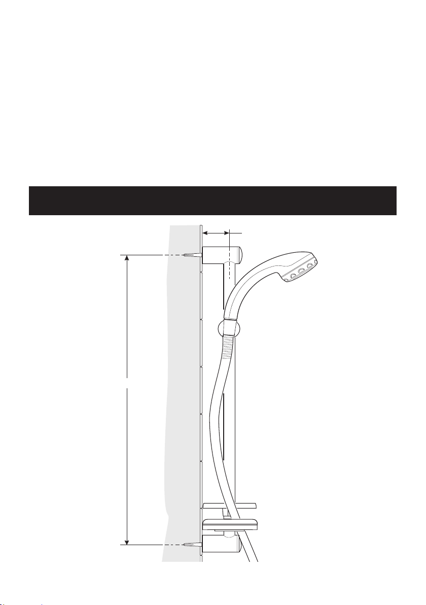
Rada Autotherm-3 EV Shower Fitting
An adjustable spray handset with three different spray actions (start, force, soothe),
and an economy setting*, supplied complete with flexible hose, clamp bracket assembly,
slide bar, supports, soap dish, two parking sockets and hose retaining ring. Suitable
for connection to surface mounted shower controls. Available in chrome finish.
The adjustable spray handset is supplied with a low capacity spray plate fitted, a
high capacity plate is also supplied.
Rada Autotherm-3 EV CAT 5 Shower Fitting
Designed to comply with the requirements of a Fluid Category 5 risk installation (as
detailed in Water Regulations). As above but with special patented Security Hose
Retaining Ring** which replaces the standard hose retaining ring and no parking
sockets.
Rada BSM Shower Fitting
An adjustable spray handset,with three different spray actions. Supplied complete
with flexible hose, clamp bracket assembly, slide bar, hose retainer and supports.