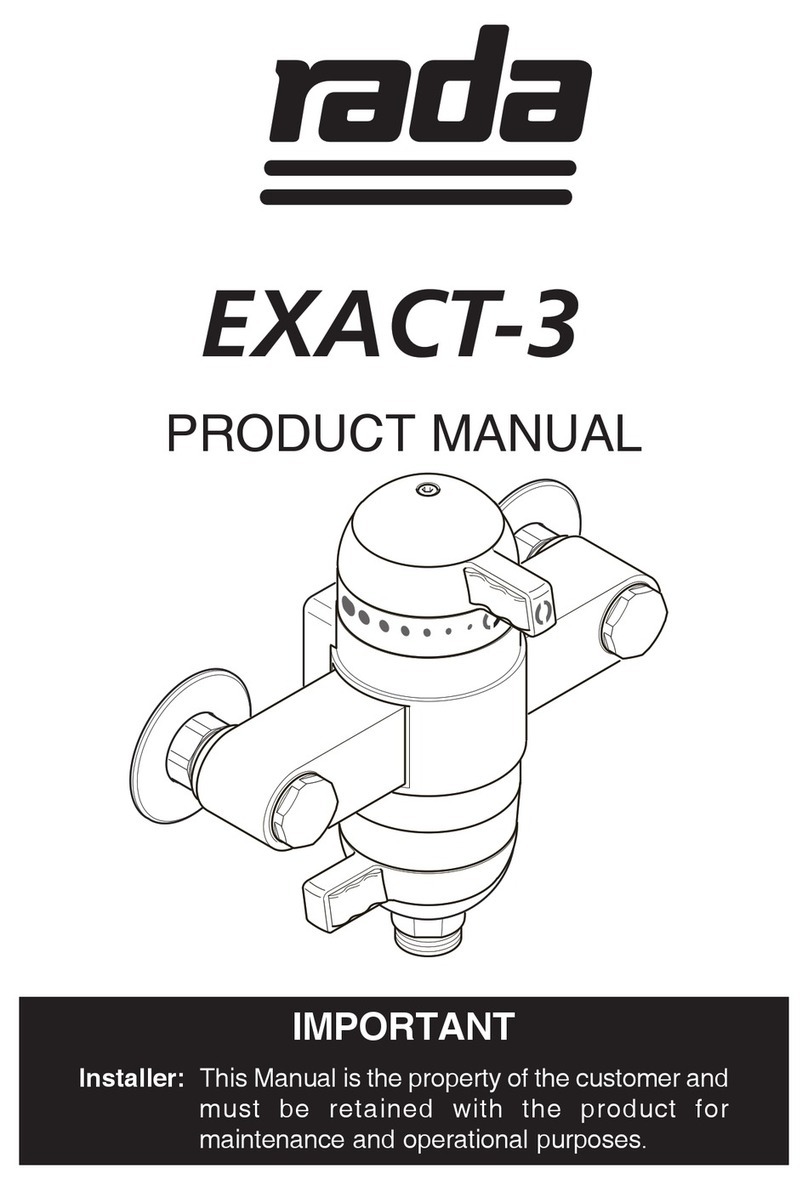
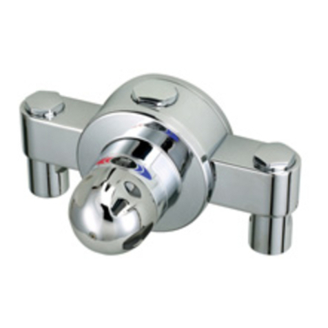
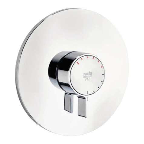
rada 215-t3 Series User manual

1
IMPORTANT
Installer: This Manual is the property of the customer and
must be retained with the product for
maintenance and operational purposes.
PRODUCT MANUAL
215-t3/222-t3 SERIES

2
INDEX
Page
SAFETY WARNINGS 3
ADVICE 3
INTRODUCTION 4
DESCRIPTION 4
DIMENSIONS 6
SPECIFICATION 8
INSTALLATION 12
COMMISSIONING 20
OPERATION 24
FAULT DIAGNOSIS 25
MAINTENANCE 26
SPARE PARTS 42
CUSTOMER CARE Back Cover
If you experience any difficulty with the installation or operation of your new
mixing valve, then please refer to the Fault Diagnosis section, before
contacting Kohler Mira Limited. Our telephone and fax numbers can be found
on the back cover of this guide.

3
SAFETY : WARNINGS
The function of this thermostatic mixing valve is to deliver water consistently at a
safe temperature. This requires that:
1. It is installed, commissioned, operated and maintained in accordance with the
recommendations given in this Manual.
2. Type 3 valves are only used for applications covered by their approved
designations.
3. Periodic attention is given, as necessary, to maintain the product in good functional
order. Recommended guidelines are given in the MAINTENANCE section.
4. Continued use of this product in conditions outside the specification limits given
in this Manual can present potential risk to users.
The use of the word ‘failsafe’ to describe the function of a thermostatic mixing
valve is both incorrect and misleading. In keeping with every other mechanism it
cannot be considered as being functionally infallible.
Provided that the thermostatic mixing valve is installed, commissioned, operated
within the specification limits and maintained according to this Manual, the risk of
malfunction, if not eliminated, is considerably reduced.
Malfunction of thermostatic mixing valves is almost always progressive in nature
and will be detected by the use of proper temperature checking and maintenance
routines.
Certain types of system can result in the thermostatic mixing valve having excessive
‘dead-legs’ of pipework. Others allow an auxiliary cold water supply to be added to the
mixed water from the mixing valve. Such systems can disguise the onset of
thermostatic mixing valve malfunction.
Ultimately, the user or attendant must exercise due diligence to ensure that the delivery
of warm water is at a stable, safe temperature. This is particularly important in such
healthcare procedures as supervised bathing of patients unable to respond immediately
to unsafe temperatures.
SAFETY : WARNINGS
ADVICE

4
INTRODUCTION
The Rada 215-t3 and Rada 222-t3 Thermostatic mixing valves are specified to meet
the highest standards of safety, comfort and economy as demanded by todays users.
All Rada products are designed, manufactured and supported in accordance with
accredited BS EN ISO 9001:1994 Quality Systems.
This Manual covers all Rada 215-t3/222-t3 series manufactured from June 1997.
The suffix t3 indicates that the valve has been certified for use in UK Healthcare
premises as a Type3 mixing valve under the TMV3 scheme. Where this product is
to be used in such an installation particular Application, Installation, Commissioning
and Maintenance requirements apply. These are given in the section 'TYPE 3 VALVES'.
A range of 1/2" and 3/4" thermostatic mixing valves to suit a wide diversity of
applications and installation formats to provide water at safe, accurate temperatures
for ablutionary or process requirements.
DESCRIPTION
Rada 215-t3 c Exposed model, surface mounted, all chrome finish, 15 mm
compression/ 1/2" BSP connections.
Rada 215-t3 bc Semi-concealed model, built-in mounting, chrome and polished
stainless steel finish, 1/2" BSP/also accepts 15 mm compression
connections.
Rada 215-t3 dk Concealed model, duct/cupboard mounting, nickel-plated finish
with white trim, 1/2" BSP external unions to accept flat-faced
connectors. (UK market models: additionally 2 elbows and 1
straight union nickel-plated connector are supplied, terminating
in 15 mm compression connections).
Rada 222-t3 dk Concealed model, duct/cupboard mounting, nickel-plated finish
with white trim, 3/4" BSP external unions to accept flat-faced
connectors. (UK market models: additionally 2 elbows and 1
straight union nickel-plated connector are supplied, terminating in
22 mm compression connections).
All models except 215-t3 dk and 222-t3 dk are provided with adjustable temperature
control which allows the user to select blend water temperatures up to a preset safe
maximum level.
All models are supplied with optional temperature-locking facility (standard on dk
models).

5
Model Range References:
c - all chrome finish
b - built-into wall recess or panel, temperature knob protrudes through stainless steel
plate.
d - duct or fully concealed mounting, no user access required.
k - locked temperature control, requires wrench key to adjust.
(+st/st: concealing plate on built-in models is polished stainless steel).
Product Selector
215-t3c 215-t3bc
Format:
Built-in
Exposed 9
215-t3dk 222-t3dk
Finish:
Duct/concealed
White trim/nickel
All chrome
Control:
Adjustable temp.
Locked temp.
Connections:
(UK only) 15 mm
(UK only) 22 mm
1/2"
3/4"
9
9
9
9
9
99
9
9
9
9
99
9
9
9
9
9
9
9
9
(+st/st)

6
141
50-67
2-15
17
15 50
108
254
121
180
162
212
All dimensions are nominal and in mm
Rada 215-t3-c
DIMENSIONS
113
65
33
153
185
17
121
65
Rada 215-t3 bc14150-672-
151715175010825412118012165162212

7
Rada 215-t3 dk Rada 222-t3 dk
65
153
65
179
108
82
33
86
37
29 29
108
65 65

8
SPECIFICATION
Normal Operating Conditions are considered as:
- inlet dynamic pressures nominally balanced to within 10% of each other during
flow.
- a differential of approximately 50oC between the hot and cold inlet temperatures,
and with differentials of 15-35oC between the blend setting and either supply.
- daily usage of 1-6 hours.
- installation and usage environment not subject to extremes of temperature,
unauthorised tampering or wilful abuse.
Other Applications
For information on other specific applications or suitability, refer to Kohler Mira Ltd,
or Local Agent.
Disinfection
In applications where system chemical disinfection is practised, chlorine can be used
(calculated chlorine concentration of 50 mg/l (ppm) maximum in water, per one hour
dwell time, at service interval frequency). Such procedures must be conducted strictly
in accordance with the information supplied with the disinfectant and with all relevant
Guidelines/Approved Codes of Practice.
If in any doubt as to the suitability of chemical solutions, refer to Kohler Mira Ltd, or
Local Agent.
Operating Parameters
For Type 3 valves the supply conditions specified in Type 3 Valves - Application
take precedence over the operating parameters which follow.
Pressures and Flow Rates
For optimum performance, dynamic supply pressures should be nominally
equal.
Recommended Minimum Dynamic Supply Pressure: 0.15 bar (0.2 bar
healthcare).
Recommended Minimum Flow Rate: 3 l/min at mid-blend with equal dynamic
supply pressures.
Recommended Maximum Flow Rate:
215-t3 models: 35 l/min at mid-blend (which equates to maximum pressure loss
of 1.8 bar).
222-t3 models: 40 l/min at mid-blend (which equates to maximum pressure loss
of 1.2 bar).
Maximum Pressure Loss Ratio*: should not exceed 10:1, in favour of either
supply, during flow.

9
Maximum Static Pressure is 10 bar.
Recommended maximum flow velocity in pipelines is 2 metres/second.
Maximum Pressure Loss Ratio*: should not exceed 10:1, in favour of either supply,
during flow.
Recommended Maximum Dynamic Supply Pressure: 5 bar.
Maximum Static Supply Pressure: 10 bar.
Recommended maximum flow velocity in pipelines is 2 metres/second.
*PressureLossRatioisdeterminedbysubtractingtheresistancetoflowoftheoutlet
pipeworkandoutletfittings(generallyknownas"backpressure",andmeasuredatthe
outletofthemixingvalve)fromthedynamicpressuresofthehotandcoldwaterateach
inletofthemixingvalve. Thisisatitsextremewhenthemixingvalveisbeingusedat
itslowestflow-rateandwhenthemaximuminequalityoccursinthepressureofthehot
andcoldwatersupplies.
Hydraulic Restriction: Flow Rate/Pressure Loss Graph
(mixing valve only, equal dynamic supply pressures and mid-blend
temperature setting).
Flow Rate
Litres/Min.
Pressure Loss - bar
.
50
40
30
20
10
0
00.5 1.0 1.5 2.0
Rada 215
Rada 222

10
Temperatures
Optimum performance is obtained when temperature differentials of 20oCor more
exist between blend and either supply. Blend control accuracy will begin to diminish
at temperature differentials below 12oC.
Blend Temperature Range: between ambient cold and approximately 60oC,
according to hot water supply temperature.
Thermostatic Control Range: approximately 25-60oC.
Optimum Thermostatic Control Range: 30-50oC.
Recommended Minimum Cold Water Temperature: 1oC.
Recommended Maximum Hot Water Supply Temperature: 85oC.
Note! The mixing valve can accept temporary temperature excursions above 85oC
without damage, however operation of the mixing valve at such elevated supply
temperatures is not recommended. For reasons of general safety, hot water storage
temperatures should ideally be maintained at between 60-65oC where serving
ablutionary applications.
Flow Control
Rada 215-t3/222-t3 series mixing valves do not have integral flow control; appropriate
provision must be made for this in the outlet pipework.
This can be in the form of basin/bath tap, stopcock, mechanical timed-flow controller
or solenoid.
The device chosen must be non-concussive in operation.
Connections
Rada 215-t3 c - Inlets and Outlet: 1/2" BSP external union or 15 mm
compression (nut and olive provided).
Rada 215-t3 bc - Inlets and Outlet: 1/2" BSP external union or 15 mm
compression (nut and olive not provided).
Rada 215-t3 dk - Inlets and Outlet: 1/2" flat-faced external union (UK market:
2 elbows and 1 straight union connector are supplied,
terminating in 15 mm compression connections).
Rada 222-t3-dk - Inlets and Outlet: 3/4" flat-faced external union (UK market:
2 elbows and 1 straight union connector are supplied,
terminating in 22 mm compression connections).

11
Inlet/Outlet Options:
inlets:* outlet:*
215-t3 c top, bottom, rear-fed top, bottom
215-t3 bc top, bottom top, bottom
215-t3 dk/222-t3 dk any configuration any configuration
*Products are supplied in the format shown in bold.
Standard Connections are: hot - left (marked red)
cold - right (marked blue)
Outlet - top (can be altered to bottom outlet as
required, refer to INSTALLATION).
Note! Should the supplies be reversed then the mixing valve will not be able to control
temperature. This can be corrected by reversing the position of the Thermostatic
cartridge within the valve body, as described in INSTALLATION.
All models can operate in any plane, and may be inverted if necessary for pipework
layout convenience, provided hot and cold pipework is connected to the appropriate
inlets (hot - red, cold - blue).

12
6. Inlet pressure tappings which allow measurement of the inlet pressures to the
mixing valve under operating conditions are particularly recommended for
healthcare applications with Type 3 valves.
7. Pipework must be rigidly supported.
8. Pipework dead-legs should be kept to a minimum.
9. Supply pipework layout should be arranged to minimise the effect of other outlet
usage upon the dynamic pressures at the mixing valve inlets.
10. Inlet and outlet threaded joint connections should be made with PTFE tape or
liquid sealant. Do not use oil-based, non-setting jointing compounds.
11. To eliminate pipe debris it is essential that supply pipes are thoroughly
flushed through before connection to the mixing valve.
Outlet Position/Reversed Inlets
Rada 215-t3 dk and 222-t3 dk models are readily adaptable for rising or falling pipework;
the flat-faced union connectors provided allow the valve body to accept a variety of
pipework configurations, and to be reversed or inverted as appropriate.
All Rada 215-t3 series mixing valves, except 215-t3 dk, are supplied with inlet
connections configured hot - left, cold - right, and top outlet as standard. It is
essential that inlet supplies correspond with the red and blue markings on the
Thermostatic cartridge. Should the existing hot and cold pipework make this
configuration inconvenient, or a bottom outlet position be required, the valve inlets or
outlet can be reversed, as detailed below. If both the outlet and inlet positions require
INSTALLATION
General
Installation must be carried out in accordance with these instructions, and
must be conducted by designated, qualified and competent personnel.
1. Before commencing, ensure that the installation conditions comply with the
information given in SPECIFICATION. For Type 3 valves see also Installation
conditions in TYPE 3 VALVES.
2. Care must be taken during installation to prevent any risk of injury or damage.
3. The mixing valve should be positioned for easy access during use and
maintenance. All routine maintenance procedures can be conducted with the
mixing valve body in place (except for strainer and checkvalve access on
215-t3 dk and 222-t3 dk). For all models, allow a minimum 80 mm clearance in
front of the temperature control to enable removal of the Thermostatic cartridge
during maintenance.
4. Conveniently situated isolating valves must be provided for maintenance.
5. The use of supply-line or zone strainers will reduce the need to remove debris at
each mixing valve point. The recommended maximum mesh aperture dimension
for such strainers is 0.5 mm.

13
3. (Built-in models). Carefully lever off the concealing plate (408 76) by inserting
a medium slotted screwdriver blade under each corner, see MAINTENANCE Figure
2.
4. With removal clip still in place, unscrew the head nut using 35 mm A/F wrench;
this will release the body shroud and also begin to draw the Thermostatic cartridge
out of the body (see MAINTENANCE Figure 3.)
Warning! some residual water may be released. Pull the Thermostatic cartridge
free of the valve body.
5. Outlet Reversal: rotate the valve body 1/2 turn so that the outlet is in the
opposite position. Do not rotate the Thermostatic cartridge.
Reversed Inlets: rotate the Thermostatic cartridge 1/2 turn, which reverses the
position of the cartridge hot and cold inlets.
6. Carefully push the Thermostatic cartridge back into the valve body, checking
that the 2 cartridge inlet port seals remain in place, and locate cartridge lugs into
body slots.
Note! The red and blue markings on the cartridge will now not correspond with
the body markings, so to avoid future confusion remove the red and blue stickers
from the valve body.
7. Carefully align and then tighten the head nut; do not over-tighten (max torque
2.5 N/m - 1.85 lbf ft).
8. Complete INSTALLATION, if appropriate.
9. If the mixing valve body has already been installed, restore hot and cold supplies
and check for any leaks.
10. Align and refit the body shroud and temperature knob assembly/locking cap so
that the markings will be visible to the user (built-in models: first refit the concealing
plate).
11. The maximum temperature may now need resetting; check, and if necessary
refer to COMMISSIONING.
Outlet Reversal should be done prior to installation of the mixing valve body.
Reversed connections can be altered before or after the mixing valve has been
installed.
The procedure for both operations is as follows:
1. If the mixing valve body has already been installed, isolate the supplies to the
mixing valve, and open an outlet fitting to release pressure and to assist the
draining of residual water.
2. Remove the temperature knob assembly (442 01) or locking cap (408 51/52),
using 3 mm wrench key provided (see MAINTENANCE Figure 1). Do not remove
the temperature hub.
reversing, it is easier to simply rotate the complete mixing valve by 1/2 turn, and then
reposition the temperature knob or cap.

14
Installation - Rada 215-t3 c
1. When unpacked, the inlet elbows are positioned to accept falling supplies. Should
the installation require rising or rear-fed supplies then the elbows will need
adjusting: loosen each elbow grubscrew (618 22) using 2.5 mm wrench key
provided, pull the elbow away from the valve body and refit in the desired position,
and re-tighten the grubscrew.
2. Where rear-fed supplies are required, pipe concealing plates are provided which
recess into the tiling for a neater finish.
3. Loosen backplate grub screws (618 22) using 2.5 mm wrench key provided and
pull off backplate (408 73).
4. - For 15 mm compression pipework inlet or outlet connections: fit compression
nuts and olives supplied.
- For 1.2" BSP union inlet or outlet connections: fit flat-faced inserts supplied,
press in firmly (see Figure 1).
5. Mount backplate securely to wall surface, with grub screws downwards, using
wall screws/plugs provided if appropriate.
6. Important: Flush through the hot and cold supplies thoroughly before
connection to mixing valve.
7. Refit valve onto backplate and tighten grub screws.
8. Connect inlet and outlet pipework, checking that the hot and cold supplies have
been piped to the correct inlets, and check all connections are watertight.
Refer to COMMISSIONING.
Figure 1 - Inlet/outlet Connectors Supplied
215-t3 c, 215-t3 bc (outlet only)
15 mm
542 10
408 71

15
Figure 2 - 215-t3 bc - Wall Recess Mounting
Installation - Rada 215-t3 bc - wall recess
The Rada 215-t3-bc is suitable for building-in to solid, dry-lined, stud partition or dry
partition wall structures.
To allow for connection of pipework, the recess in the wall (unfinished) should be
approximately 180 mm x 117 mm x 50 mm (see Figure 2).
The depth of concealment is critical, the minimum depth to accept the mounting
bracket is 50 mm, with another 15 mm maximum on top of this for finishing coat
thickness of plaster and tiles or other material. This last dimension determines how
much of the temperature or locking knob will be visible through the concealing plate.
A building-in shroud is supplied, which protects the mixing valve during plastering/
finishing and provides a reference for the building-in depth.
1. This mixing valve is supplied with outlet to top, should the installation require
outlet to bottom, then refer to INSTALLATION.
2. When unpacked, the inlet elbows are positioned to accept falling supplies.
Should the installation require rising supplies, then the elbows will need adjusting;
loosen each elbow grubscrew (618 22) using 2.5 mm wrench key provided, pull
the elbow away from the valve body and refit on opposite inlet port so that
the Checkvalve cartridges remain facing forwards, and re-tighten the grubscrew.
3. Fit mounting bracket (407 88) to valve base using 2 screws (615 39) supplied,
and mount the valve into recess (see Figure 2), using wall screws/plugs provided
if appropriate. The mounting bracket must be horizontal.
50 mm
117 mm
180 mm

16
4. Important: Flush through the hot and cold supplies thoroughly before
connection to mixing valve.
5. Connect inlet and outlet pipework, checking that the hot and cold supplies
have been piped to the correct inlets, and check all connections are watertight.
6. Assemble building-in shroud (407 92) as shown below (Figure 3), and fit over
mixing valve in recess. Plaster and tile, or finish as appropriate, up to edge of
shroud. Final wall surface must fall between 2 lines on building-in shroud (see
Figure 3).
7. When wall surface is finished, remove the building-in shroud and temperature
knob.
8. When packed, the concealing plate bracket assembly (408 77) and concealing
plate (408 76) are assembled together. To detach, carefully lever off the
concealing plate by inserting a medium slotted screwdriver blade under each
corner, (see MAINTENANCE Figure 1).
Figure 3 - 215-t3 bc - Wall Recess Finishing
Finished wall surface
Building-in shroud

17
9. The concealing plate bracket assembly (408 77) is provided with a foam seal
on its rear face, which mates with the wall surface and reduces the possibility
of water penetration into the recess. Should the wall surface or tiling be uneven,
this seal will not be fully effective and should be assisted/substituted by silicone
sealant.
Align and secure concealing plate bracket assembly to mounting bracket with
2 each of 30 mm panhead stainless steel screws (616 52), washers (642 10) and
nuts (626 26) provided.
10. Remove protective film from concealing plate (408 76), and align into position
with bracket. Press firmly at each corner to secure. Refit temperature knob.
Refer to COMMISSIONING.
Installation - Rada 215-t3 bc - thin panel
The Rada 215-t3 bc incorporates a mounting bracket, enabling the valve to be installed
through a laminated panel or shower cubicle.
The bracket must be mounted to the rear face of panels of 2-15 mm finished thickness
(see below for thicker panels).
The rear clearance requirement is 50 mm
1. Cut a hole in the panel measuring 180 x 117 mm
2. Drill 2 fixing holes of 4 mm diameter at 212 mm centres in the positions shown on
Figure 4 and Figure 5.
3. Follow previous instructions 1-2 for wall recess installation.
4. Fit mounting bracket (407 88) to valve base using 2 screws (615 39) supplied. If
access is available it may be preferable to make the initial valve/pipework
connections prior to securing the mixing valve to the panel.
5. Mount the mixing valve securely onto rear of panel (see Figure 5), with 2 each of
30 mm panhead stainless steel screws (616 52), washers (642 10) and nuts
(626 26) provided.
6. Important: Flush through the hot and cold supplies thoroughly before
connection to mixing valve.
7. Connect inlet and outlet pipework, checking that the hot and cold supplies have
been piped to the correct inlets, and check all connections are watertight.
8. Follow previous instructions 7-10 for wall recess installation.
Refer to COMMISSIONING.

18
Figure 5
Figure 4 - Mounting 215-t3 bc to panel (2-15 mm)
2-15 mm 180 mm
117 mm
15 mm
2 - 15 mm
50 mm
Installation - Rada 215-t3 bc - Panels 16 mm
Note! The mounting bracket can also be mounted to the front face of thicker panels
which will receive a further finishing layer of 2-17 mm thickness. If this further
finishing layer is not to be provided, the ends of the mounting bracket must be
recessed 2 mm depth) into the panel face until flush.
1. Cut a hole in the panel measuring 180 x 117 mm.
2. Drill 2 fixing holes at centres of 212 mm in positions marked on Figure 4. The
fixing hole dimensions must be suitable for the selected securing method,
appropriate for the particular panel material.
212 mm
180 mm

19
3. Follow previous instructions 1-2 for wall recess installation.
Note! The inlets accept rising or falling supplies, on thicker panels this may
require the inlet pipework to be configured with elbows or pipe bends immediately
prior to the inlet connections.
4. Fit mounting bracket (407 88) to valve base using 2 screws (615 39) supplied.
If access is available it may be preferable to make the initial valve/pipework
connections prior to securing the valve to the panel.
5. Mount valve securely into recess (see Figure 5), using drilled 212 mm hole
centres.
6. Important! Flush through the hot and cold supplies thoroughly before
connection to mixing valve.
7. Connect inlet and outlet pipework, checking that the hot and cold supplies have
been piped to the correct inlets, and check all connections are watertight.
8. Plaster and tile, or finish as appropriate, up to the panel hole perimeter only,
and to a maximum thickness of 15 mm over the front face of the mounting
bracket. Protect the mixing valve and pipe connections during this process.
9. Follow Rada 215-t3 bc instructions 7-10 for wall recess installation. Refer to
COMMISSIONING.
Installation - Rada 215-t3 dk and 222-t3 dk
1. The mixing valve is supported by its inlet and outlet pipework only, which must
be suitably and securely fastened.
2. Inlets and outlet are external BSP union, intended to accept flat-faced connectors.
It is recommended that such union connections are used, so that the mixing
valve body can be readily removed from its pipework for maintenance purposes.
(UK market models:) Three additional connectors are supplied (2 elbows, 1
straight, terminating in compression connections), which are interchangeable
to the inlets and outlet. Select the most appropriate configuration for the intended
installation, and, with nylon washers (636 10/11) in place, secure to valve body.
3. Run inlet and outlet pipework to the mixing valve, checking that hot and cold
supplies have been piped to the correct inlets.
4. Important: Flush through the hot and cold supplies thoroughly before
connection to mixing valve.
5. Connect inlet and outlet pipework, checking that the hot and cold supplies have
been piped to the correct inlets, and check all connections are watertight.
Refer to COMMISSIONING.

20
COMMISSIONING
Commissioning must be carried out in accordance with these instructions, and must
be conducted by designated, qualified and competent personnel.
Exercising the Thermostat
Thermostatic mixing valves with wax thermostats are inclined to lose their
responsiveness if not used. Valves which have been in storage, installed but not
commissioned, or simply not used for some time should be exercised before setting
the maximum temperature or carrying out any tests.
A simple way to provide this exercise is:
(a) ensure that the hot and cold water are available at the valve inlets, and the
outlet is open.
(b) move the temperature control rapidly from cold to hot and hot back to cold
several times, pausing at each extreme.
Maximum Temperature
The maximum blend temperature obtainable by the user should be limited, to prevent
accidental selection of a temperature that is too hot.
All Rada Thermostatic mixing valves are fully performance tested and the maximum
temperature is preset to approximately 43oC under ideal installation conditions at the
factory.
Site conditions and personal preference may dictate that the maximum temperature
has to be reset following installation. For Type 3 valves in healthcare installations the
maximum blend temperature is determined by the application - see Table under
Application and Designation Information for Type 3 Valves.
This mixing valve is provided with two methods of temperature setting, a levered
adjustable temperature control knob which allows the user to select the blend
temperature between ambient cold up to a preset maximum, or if considered more
appropriate, a locked cap can be fitted, allowing no user adjustment.
Maximum Temperature Setting
Check that an adequate supply of hot water is available at the hot inlet of the mixing
valve.
The minimum temperature of the hot water must be at least 12oC above the desired
blend, however during resetting this should be close to the typical storage maximum
to offset the possibility of any blend shift due to fluctuating supply temperatures.
Check that both inlet isolating valves are fully open.
Temperatures should always be recorded using a thermometer with proven accuracy.
This manual suits for next models
1
Table of contents
Other rada Plumbing Product manuals
Popular Plumbing Product manuals by other brands

SFA
SFA SANICUBIC 1 Installation and maintenance instructions

Pfister
Pfister Contempra R89-SNC Quick installation guide

Galvin Specialised
Galvin Specialised Ezy-Drink Lead Safe Product installation guideline

Schell
Schell EDITION E 02 806 06 99 Assembly and installation instructions

Hans Grohe
Hans Grohe Vernis Shape 71463000 Instructions for use/assembly instructions

Toto
Toto TS100MC3 Installation and owner's manual