RADEMACHER RolloHomeControl Troll Standard 3650 03 12 Product guide

VBD 592-2 (09.13)
Troll Standard
Operating and Assembly Manual for 50mm Switch Range
Item No:
3650 03 12 (ultra-white)
3650 03 22 (aluminium)
EN

2
iEN
Dear Customer,
These instructions...
...describe how to install, connect the electrical system and
operate your Troll Standard.
Before you begin, please read these instructions
through completely and follow all the safety
instructions.
Please store these instructions in a safe place and pass them on
to any future owners.
Damage resulting from non-compliance with these instructions
and safety instructions will void the guarantee. We assume no
liability for any resulting damage.
With your purchase of a Troll Standard, you have chosen a
quality product manufactured by RADEMACHER. Thank you for
the trust you have placed in us.
The Troll Standard has been designed in order to provide
optimal convenience and operability as well as to ensure solidity
and durability. Having applied uncompromising quality standards
and thorough testing, we are proud to be able to present you this
innovative product.
It’s brought to you by all the
highly-qualied personnel here at
RADEMACHER.

3
iEN
Table of Contents
1. Scope of delivery / general view ..........................4
2. The key functions .................................................5
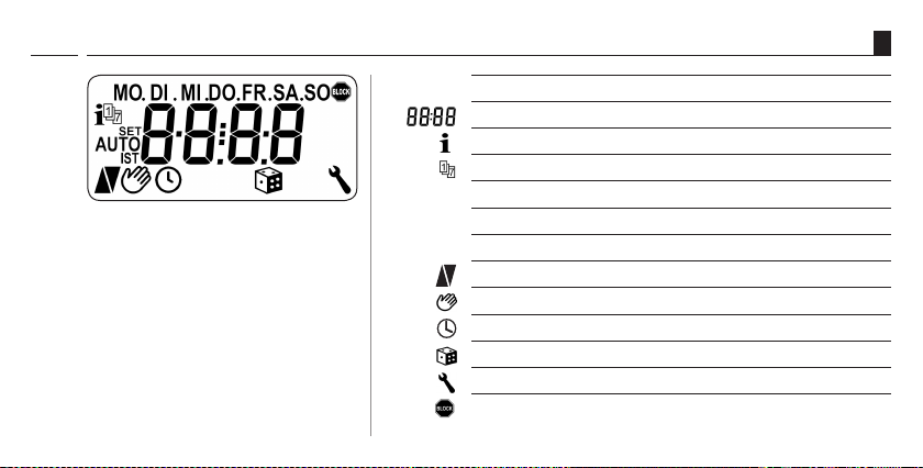
3. Display symbol legend .........................................6
4. Menu overview ....................................................7
5. Key to symbols ....................................................8
6. General safety information ..................................9
7. Proper use .........................................................10
8. Improper use .....................................................10
9. Brief description ................................................11
9.1 Compatible switch ranges. .......................12
10. Overview of features ..........................................13
11. Important information prior to electrical
installation and mounting .................................14
12. Safety instructions for electrical connection ......16
13. Electrical connection of the Troll Standard .........17
14. Assembly ...........................................................18
15. Brief description of the standard display
and main menu .................................................19
15.1 Opening and closing the menus
(example: activating the
random function).....................................20
16. Initial commissioning with the help of the
installation wizard .............................................21
17. Manual operation ..............................................23
18. Memory function - accepting the current time
as switching time ..............................................24
19. Menu overview / main menu .............................25
19.1 [ AUTO ] Automatic mode;
brief description.......................................26
19.2 Menu 1- Automatic mode on / o ............27
19.3 Switching times (opening and
closing times) [ / ];
brief description.......................................28
19.4 Menu 2 - Conguration of opening
and closing times [ / ]. .......................29
19.5 Menu 6 - Conguring the random
function [ ] .........................................30
20. Menu 9 - System settings [ ];
brief description ................................................31
20.1 Menu 9.1 - Set time and date [ ] .......32
20.2 Select Menu 9.5 - Switching time
programme [ ] ..................................33
20.3 Menu 9.6 - Conguration of
blockage detection [ ] ........................34
20.4 Menu 9.8.1 - Automatic summer/winter
changeover on/o ...................................37
20.5 Menu 9.8.2 - Set display contrast .............38
20.6 Menu 9.8.4 - Set clock mode ....................38
20.7 Menu 9.8.5 - Switch key lock on/o .........39
20.8 Menu 9.8.7 - Switch reversal of
rotation direction on/o ..........................40
20.9 Menu 9.8.0 - Display software version .....41
21. Software reset (restore factory settings). ...........42
22. Hardware reset ..................................................43
23. Dismantling .......................................................44
24. CE Mark and EC Conformity ................................45
25. Technical specications and factory settings ......46
26. Warranty conditions ..........................................47

4
iEN
1. Scope of delivery / general view
Set key
Display
Set key
1.
2.
3.
Legend
1. Operating unit (50 x 50) mm
2. Frame
3. Installation housing
4. 1 x operating manual (not illustrated)
SET/Stop key
Down key
OK key
Up key
[ 1 ] Operating unit
Menu key

5
iEN
2. The key functions
The operating keys [ up / down ]
◆Manual operation [ up / down ].
SET/Stop key, [ ]
◆Manual roller shutter stop.
◆Conguration (setting) of various functions.
Menu key, [ M ]
◆Call up the main menu.
◆Go back or return to the standard display.
The set keys, [ / ]
◆ Selects the desired menu item.
◆Setting the parameters (increase / decrease) / pressing
and holding a key for an extended period causes the digits
to change more quickly.
[ OK ] key
◆Conrms and opens the selected menu.
◆Conrm entry.
◆Continue to next entry.

6
iEN
3. Display symbol legend
[ SET ]
[ AUTO ]
[ MO ... SO ] Week days (MON...SUN)
Time / setting parameters
Information
Switching programme
Setting
Automatic operation
ACTUAL value
Direction of travel - up / down
Automatic mode o
Timer periods
Random function
System settings
Blockage detection
[ IST ]

7
iEN
4. Menu overview
[ 1 ] Automatic mode
[ 2 ] Switching times
> On / OFF
> On / OFF
Main menu
[ 6 ] Random function > On / OFF
[ 9 ] System settings
> 9.1 Time/date
> 9.5 Switching time programme
> 9.6 Blockage detection
> 9.8. Device settings
> 9.8.1 Automatic summer/winter changeover
> 9.8.2 Display contrast
> 9.8.4 Clock mode
> 9.8.5 Key lock
> 9.8.7 Reversal of rotation direction
> 9.8.0 Software version

8
iEN
5. Key to symbols
Risk of fatal electric shock.
This symbol warns of danger when working on electrical
connections, components, etc. It requires that safety precautions
be taken to protect the life and health of the person concerned.
This concerns
your safety.
Please pay particular attention and carefully follow all instructions
marked with this symbol.
STOP
NOTE / IMPORTANT / CAUTION
In this way, we wish to make you aware of the following content
in order to ensure optimal functionality.
Please read the operating instructions for an external device
described at this point, (e.g. a tubular motor).

9
iEN
STOP
Danger due to electric shock when working on all
electrical systems.
◆The electrical connection and all work on electrical
systems must only be carried out by a qualied electrician
in accordance with the connection instructions in these
operating instructions, see page 17.
◆Carry out all installation and connection work only in an
isolated, de-energised state.
6. General safety information
Incorrect use leads to an increased
risk of injury.
◆ Children may not be permitted to play with the Troll
Standard.
◆Train all personnel to use the Troll Standard safely.
◆Avoid allowing persons with limited abilities to operate
the equipment and prevent children from playing with
xed controllers.
◆Never remove the operating unit from the installation
housing during operation.
The use of defective equipment can lead to personal injury
and damage to property (electric shocks, short circuiting).
◆Never use defective or damaged equipment.
Please contact our Customer Service department in the
event of faults, see page 48.

10
iEN
7. Proper use
Only use the Troll Standard for connecting and controlling a
tubular motor for Venetian blinds, slats or awnings.
Operating conditions:
◆The tubular motor must be tted with a mechanical or
electronic end position switch.
◆ Only operate the Troll Standard in dry rooms.
◆ A 230 V / 50 Hz power supply, together with a site-provided
disconnecting device (fuse, MCB), must be available at the
installation location.
8. Improper use
Using the Troll Standard for purposes other than
previously mentioned is impermissible.
◆Do not install the Troll Standard outside.
i

11
iEN
9. Brief description
The Troll Standard controller is designed for controlling roller
shutters, Venetian blinds, slats or awnings by connecting a
corresponding tubular motor.
Roller shutter control
The system enables roller shutters to be automated.
Manual operation
It is possible to manually control the connected tubular motor at
any time by using the controls.
External controller via the two inputs E1 and E2.
The Troll Standard features two inputs E1 and E2 (230 V / 50 Hz)
for connecting an external sensor or external controller (e.g. Troll
Comfort), see page 17.
Brief description of blockage detection function
The Troll Standard is able to monitor the torque of motors
equipped with mechanical end point setting. This enables
the controller to switch o the motor in the event of overloading
or blockage, see page 34.
Installation (see page 18)
The Troll Standard can be integrated into most commercially
available switch ranges with the help of a corresponding
intermediate frame 50 x 50 (DIN 49075). Suitable switch ranges
are detailed on the following page.

12
iEN
Manufacturer switch range
BERKER Arsys / K1 / S1
BUSCH-JAEGER Busch-Duro 2000 Si / Reex Si / alpha
exclusive / alpha nea / solo / impuls
GIRA Standard-System / S-Color
System / stainless steel range /
Standard 55
JUNG CD 500 / ST 550 / LS 990 / CDplus and
CD, however, with coloured rings
MERTEN M1 / Atelier / Artec / Trancent /
Antik Neu
PEHA Standard / Dialog / Aura
LEGRAND Creo / Tenara
VEDDER Alessa (plus)
9.1 Compatible switch ranges.
NOTE
◆It may be necessary to use an intermediate frame 50 x 50 *
(DIN 49075), depending on the respective switch range used.
* not included

13
iEN
10. Overview of features
◆Installation wizard for easy commissioning.
◆Congurable blockage detection for mechanical tubular motors
◆Manual operation on site
◆AUTO/MANU - switchover
◆Easy conguration with menu-driven operation
◆Timer periods
■Conguration of an opening [ ] and
closing time [ ] for your roller shutters.
◆Switching programme:
■Weekly switching times
–One switching time pair [ / ] for (MON...SUN)
[ MO...SO ]
■Weekday and weekend switching times
–One switching time pair [ / ] for (MON...FRI)
[ MO...FR ]
–One switching time pair [ / ] for (SAT + SUN)
[ SA + SO ]
◆Random function (random delay of 0 to 30 minutes)
◆Key lock
◆Memory function (easy acceptance of the current time as
switching time)
◆Permanent storage of the settings
◆Automatic summer / winter changeover
◆Reversal of direction of rotation
◆External control via the two inputs E1 / E2
Description and conguration of the individual
functions
A precise description of the individual functions and settings is
included starting on page 19.

14
i
[ 3 ]
[ 4 ]
EN
Installation and electrical connection of the Troll Standard
may only be undertaken with the supplied installation
housing [ 3 ].
The connecting terminals [ 4 ] are located at the bottom of the
installation housing [ 3 ].
11. Important information prior to electrical installation and mounting
NOTE
Installation housings for other variants of the Troll controller are
not compatible.
You must congure the end stops for the tubular motor
before using for the first time and making the final
electrical connection.
◆If no end stops are congured, then it is vital that both end
points are congured for the tubular motor, as failure to do
so can lead to malfunctions.
◆In order to do so, follow the information provided in the
operating manual for the respective tubular motor.

15
EN
Parallel connection of electronic tubular motors
A maximum of 3 tubular motors can be connected in parallel
to the controller (e.g. RADEMACHER electronic tubular motors).
To do so, please refer to the operating manual for the
corresponding tubular motor.
11. Important information prior to electrical installation and mounting
i
Requirements for blockage detection
Blockage detection is only operational if a mechanical tubular
motor is connected.
Function of inputs E1 / E2
E1 = UP
E2 = DOWN
NOTE
The external signals to inputs E1 and E2 are only taken into
consideration when the automatic mode is activated.
Parallel connection of mechanical tubular motors
A cut-o relay is required in order to connect mechanical tubular
motors in parallel.

16
iEN
12. Safety instructions for electrical connection
Danger due to electric shock when working on all
electrical systems.
◆ The electrical connection and all work on electrical
systems must only be carried out by a qualied electrician
in accordance with the connection instructions in these
operating instructions.
◆ Carry out all installation and connection work only in an
isolated, zero-volts state.
◆ Disconnect all phases of the mains power supply cable and
secure it to prevent any reconnection.
◆ Check the system for a zero-voltage status.
◆ Prior to connecting, compare the information about voltage /
frequency on the device with that of the local electrical grid
operator.
Incorrect wiring may lead to short-circuits and destroy
the device.
◆ Follow the pin assignment detailed in the wiring diagram.
◆ Follow all the electrical connection specications in the
operating instructions of your tubular motor.
Connection of a second phase to E1 or E2 will cause the
Troll Standard to be damaged.
◆When inputs E1 / E2 are used, they must always be
connected to the same phase.
◆If another phase is connected, the incorrect mains voltage
(380 V / 50 Hz) will be applied to the inputs and damage
the Troll Standard.
STOP

17
iEN
13. Electrical connection of the Troll Standard
Connecting the white set lead (SET) from
RADEMACHER tubular motors
* The white set lead (SET) from RADEMACHER
tubular motors must be connected to the neutral
terminal [ N ] to ensure trouble-free operation of
the tubular motor.
Inputs E1 / E2 (230 V / 50 Hz) , only if required.

18
i
[ 1 ]
[ 2 ]
[ 3 ]
[ 5 ]
EN
14. Assembly
The Troll Standard is designed for ush-mounted installation.
For this, you require a 58 mm ush-mounted box. We
recommend using a deep box.
Installation procedure:
1. Switch o the mains.
2. Make the electrical connection according to the wiring diagram
(see page 17).
3. Route the power cables to the ush-mounted box.
4. Slide the installation housing [ 3 ] into the ush-mounted box and
clamp the claws [ 5 ] in place with the screws provided.
5. Fit the frame [ 2 ].
6. Carefully insert the operating unit [ 1 ] into the installation
housing [ 3 ].
7. Switch the mains power again back on again.

19
iEN
15. Brief description of the standard display and main menu
The standard display (example) The main menu
◆Displays the current day of the week and time.
◆Displays the activated functions.
◆Manual operation of the Troll Standard is only possible
from the standard display.
◆Enables display and selection of the individual functions
and menus.
◆Manual operation is not possible from the main menu.
◆No automatic control commands will be executed during
the conguration process.
◆If no key is pressed within 120 seconds, the display auto-
matically changes from the active menu back to the stan-
dard display. Changes to settings are nevertheless saved.
Functions /
menus
Menu
number

20
iEN
1. Call up the main
menu.
By pressing the
[ M ]-key in the standard
display.
15.1 Opening and closing the menus (example: activating the random function)
3. Open the menu by
pressing the [ OK ]
button.
The selected menu is indicated
by a ashing icon.
4. Select the desired setting
and conrm with [ OK ].
2. Select the desired
menu or menu number.
NOTE
Pressing the [ M ]-key
from any of the menus
will return you to the
standard display.
approx. 1
sec.
5. Subsequently the main
menu will be displayed
again.
This manual suits for next models
1
Table of contents
Other RADEMACHER Home Automation manuals

RADEMACHER
RADEMACHER RolloTron Basic 1100 User manual

RADEMACHER
RADEMACHER RolloTron Comfort 1623 45 19 Product guide

RADEMACHER
RADEMACHER RolloTron Basic DuoFern 1200 User manual

RADEMACHER
RADEMACHER superrollo ST110 User manual

RADEMACHER
RADEMACHER HomePilot Installation and operation manual

RADEMACHER
RADEMACHER Delta Dore Stick User manual

RADEMACHER
RADEMACHER Start2Smart User manual

RADEMACHER
RADEMACHER RolloTron Basis 1100 User manual