manuals.online logo
Brands
  1. Home
  2. •
  3. Brands
  4. •
  5. Radio Shack
  6. •
  7. Multimeter
  8. •
  9. Radio Shack 22-174A User manual

Radio Shack 22-174A User manual

Other Radio Shack Multimeter manuals

Radio Shack 22-178 User manual

Radio Shack

Radio Shack 22-178 User manual

Radio Shack 22-602 User manual

Radio Shack

Radio Shack 22-602 User manual

Radio Shack 2200087 User manual

Radio Shack

Radio Shack 2200087 User manual

Radio Shack 22-812 User manual

Radio Shack

Radio Shack 22-812 User manual

Radio Shack 22-812 User manual

Radio Shack

Radio Shack 22-812 User manual

Radio Shack 22-813 User manual

Radio Shack

Radio Shack 22-813 User manual

Radio Shack 22-812 User manual

Radio Shack

Radio Shack 22-812 User manual

Radio Shack 2200813 User manual

Radio Shack

Radio Shack 2200813 User manual

Radio Shack 22-218 User manual

Radio Shack

Radio Shack 22-218 User manual

Radio Shack 22-168A User manual

Radio Shack

Radio Shack 22-168A User manual

Radio Shack 22-812A User manual

Radio Shack

Radio Shack 22-812A User manual

Popular Multimeter manuals by other brands

Fluke 106 user manual

Fluke

Fluke 106 user manual

VAR DV-71600 manual

VAR

VAR DV-71600 manual

Agilent Technologies 34420A user guide

Agilent Technologies

Agilent Technologies 34420A user guide

Fluke 83 user manual

Fluke

Fluke 83 user manual

Hameg HM 8012 manual

Hameg

Hameg HM 8012 manual

Mastech MY70 Operation manual

Mastech

Mastech MY70 Operation manual

Steren MUL-300 user manual

Steren

Steren MUL-300 user manual

Somogyi Elektronic home SMA 92 instruction manual

Somogyi Elektronic

Somogyi Elektronic home SMA 92 instruction manual

Gossen MetraWatt METRAmax 6 operating instructions

Gossen MetraWatt

Gossen MetraWatt METRAmax 6 operating instructions

PeakTech 4000 Procedure of calibration

PeakTech

PeakTech 4000 Procedure of calibration

YOKOGAWA 90050B user manual

YOKOGAWA

YOKOGAWA 90050B user manual

Fluke 8846A Programmer's manual

Fluke

Fluke 8846A Programmer's manual

Tempo Communications MM200 instruction manual

Tempo Communications

Tempo Communications MM200 instruction manual

APPA 607 user manual

APPA

APPA 607 user manual

Elenco Electronics CM-1555 operating instructions

Elenco Electronics

Elenco Electronics CM-1555 operating instructions

Mastech MS8238C user manual

Mastech

Mastech MS8238C user manual

SDAR 830A, 830B, 830D, 830C user manual

SDAR

SDAR 830A, 830B, 830D, 830C user manual

RS PRO RS-9519BT instruction manual

RS PRO

RS PRO RS-9519BT instruction manual

manuals.online logo
manuals.online logoBrands
  • About & Mission
  • Contact us
  • Privacy Policy
  • Terms and Conditions

Copyright 2025 Manuals.Online. All Rights Reserved.

Cat. No.22-174A
OWNER'S MANUAL
Please read before using this equipment.
Radpfhaek@
FEATURES
This Radio Shack True RMS Multimeter is a portable,
92ls-digit meter ideal for field, lab, shop, berich, anci
home use. The meter uses the latest lC and display
technology to achieve the lowest possible component
count, and the true RMS converter is built into d single
multimeter chip. These features make the meter rugg-
ed .and.gqsy io use and ensure reliability, accuralc!,
and stability. Your meter also includes the fbllowing b+
tures.
LCD Bar Graph Display - makes nulls, peaks, and tends
more apparent.
Translstor-Check Function - measures the gain (hre) of
small-signal, bipolar transistors and identifies pinout and type.
;fllly AuteRanglng - makes your meter easier and safer to
-use by letting you concentrate on the probes, and also lets you
manually set the range lor situations where you know what val-
ues to expect.
Volts or dBm Voltage Display - lets you select the unil of
measure that suits your application.
Dat+Hold Functon - freezes the display so you can view
the reading even after you disconnect the leads.
Condnulty Functlon - quickly checks the continuity of wires
or traces.
True RMS Operation - gives a more accurate reading for
non-sine wave AC measurements.
Effective Overload and Translent Protectlon - covers all
ranges except the DC/AC 10A range.
@ 199a Tandy Corporation,
All Bights Rceerved.
Radio Shack io a reglatered trEdomark
' uaed by Tandy Corporatlon.
2
Full Auto-Polarity Operation - protects your meter and
gives valid measurements when you connect the leads in rs.
verse polarity.
Frequency Counter - measures frequencies up to 2 MHz.
Diod+Check Function - safely checks semiconductors for
open, shorted, or normal junctions.
Low-Battery lndication - shows you when battery power is
low by displaying a low-battery indicator.
Folding Wire Stand - lets you use the meter on a bench top.
UL Listed - passes the stringent tests required by Undenrtrrii-
ers Laboratories for safety.
Built-ln Temperature Function - measures temperatures
tro1r - 58"F to 302"F (- 50'C to 150'C) and gives the readilFp
in Fahrenheit (F) or Celsius (C). 'l')'
Cautions:
o Completely read this manual belore you use the meter.
r ll you are not familiar with meters and testing procedures,
we suggest that you obtain and read a book about the sub
ject, such as "Using Your Metef'(Radio Shack Cat. No.62-
2039).
CONTENTS
A Word About Safety ................... 5
What Does "True RMS" Mean? ...."................... Z
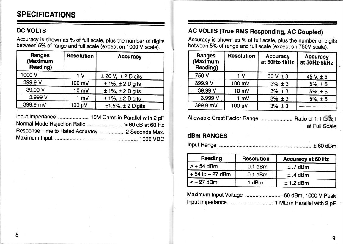
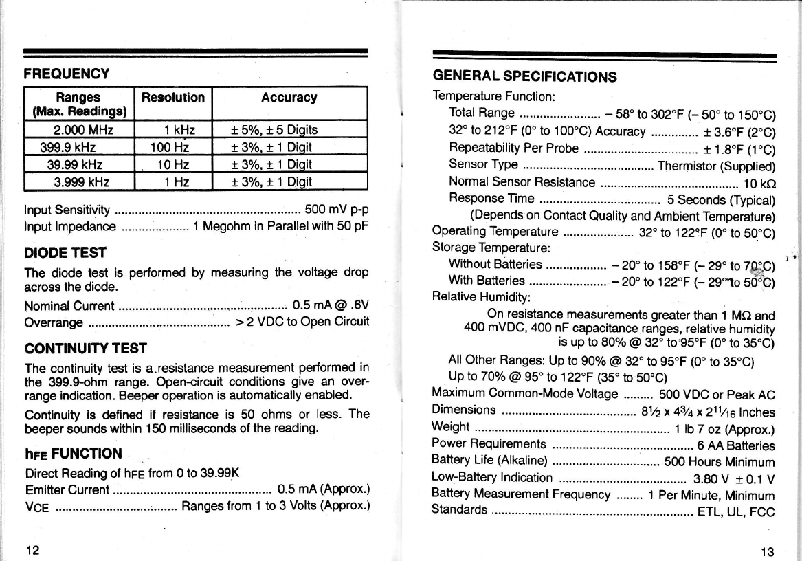
Specifications ........ g
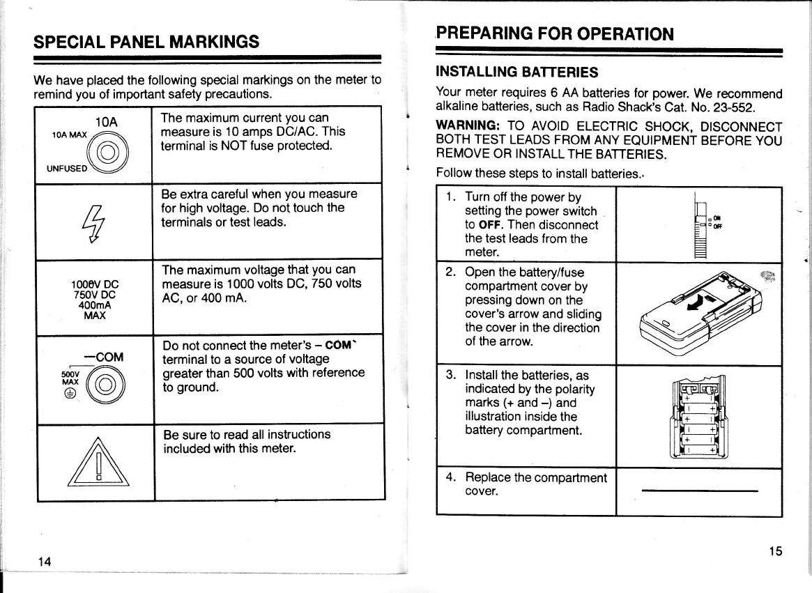
Special PanelMarkings .................. ................. 14
Preparing for Operation ............. 15
lnstalling Batteries ................. 15
Using Test Leads ........... ....... 16
Making Measurements ................. ................... 17
Turning On the Meter ........... ....................... 17
Understanding Phantom Readings ............ 1T
Overrange lndication ............. jZ
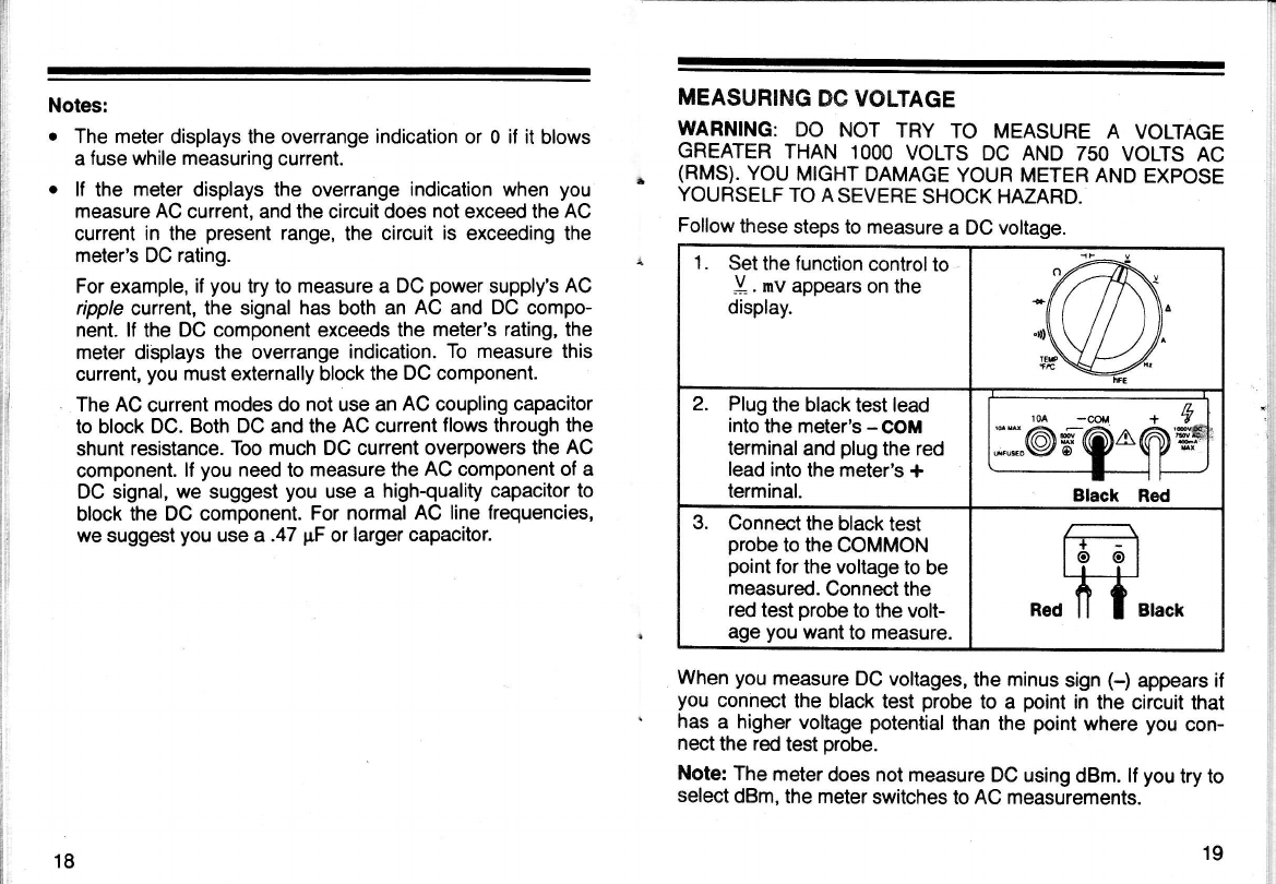
Measuring DC Voltage ......... 19
Measuring AC Voltage ......... 20
Measuring an AC Voltage on a DC Bias ......................-... 21
Measuring 3-Phase AC Voltages _-...-----....- 22
Measuring AC/DC Current ......-......-_......... 23
Measuring Resistance ......... 26
Checking Continuity ........ 29
Checking Diodes ............-...... gO
Checking Transistors ..-.-...... 92
Measuring Frequency .......... 35
Measuring Capacitance --..... 97
Using the Hold Function ....... 38
Using the Bar Graph ............. 39
Manually Selecting the Range ...".....--........ 39
Using the Beep Function ......-........... .......... 40
Using the Temperature Function ................. 40
Maintenance ....... 42
Replacing the Fuses ............. 42
Caring lor the Meter ................... 44
Lg hSug taken every precaution in designing this meter to en_
sure that it is as safe as we can.mat<e'it. g"ui, safe op"i"fion
depends qn yqu, the operator. We ,ecommbnd you follow
these simple safety rules:
o Never.apply voltages to the meter that exceed the limits
$:'' ?Jffi ffi3'[3' !:il]"Jff lRy,ii:n,X5: l,?3fj
apply more than 500V DC or 500V Ril,ts A-C dtu;;;;i
input terminal and ground.
o Use extreme caution when you work with voltages above
40V. Atways disconnect power from tfrJ circuii t* t;
measuring before you connect test leads to tigh;tAJ
points.
o Never connect test leads to a source of voltagb when yofr
select. the diode, ohms,. continuity, crrrent -reasurement,
capacitance, or hre functions.
I Always discharge filter capacitors in the power supply of the
circuit under test before you attach test leads.
o flwqVs turn off the meter's power and disconnect the test
leads before you replace thebatteriei ;ril;;.
o Never.operate the meter unless the battery cover is in place
and fully closed.
. P::::"^lany AC/DC sets.have a potentiaily hol chassis,
?e_ sure rhe top of your workbench and the flo6r underneath
tr are made of non_conductive materials.
.f.fe rytJiryter is. fulty catibrated and tested. Under normat
!lp-,_no,lrtllr"r adjustment is necessary. tf the meter does re.
eurr€ adjrrs1llg, do not try to adjust.it yourself. Take it to your
nearesl Radio Shack store. Service Uy unautfrorizeA perso,nnet
voids the waranty.
A WORD ABOUT SAFETY
WARNING: USE EXTREME CAUTION lN USE OF THIS DE-
VICE. IMPROPER USE OF THIS DEVICE CAN RESULT IN
INJURY OR DEATH. FOLLOW ALL SAFEGUARDS SUG.
GESTED IN THE OWNER'S MANUAL IN ADDITION TO NOR-
MA! SAFEW PRECAUTIONS IN DEALING WITH ELECTRI-
CAL CIRCUITS. DO NOT USE THIS DEVICE IF YOU ARE
UNFAMILIAR WITH ELECTRICAL CIRCUITS AND TESTING
PROCEDURES.
NOT FOR COMMERCIALOR INDUSTRIAL USE.
WHAT DOES'TRUE RMS' MEAN?
RMS stands lor Root-Mean-Square. RMS is a standard
method for determiriing the effective value of a varying or alter-
nating voltage. The RMS value is the DC voltage that would
produce the same amount ol heat as the voltage you are
measuring, if you were to apply both voltages across identical
resistors.
The true RMS value is helpful when you need to measure an
AC voltage that is not a pure sine wave. Most meters uS€ oVOr.
ageresponding AC converters. These meters are calibrated
with pure sine waves. lf you measure a sine wave that does
not have harmonic distortion, the m.eter gives an accurate
reading. But, if the sine wave is not pure-there are distor-
tions within the waveform, or you measure triangle waves or
square waves - the average.responding meters display an in-.
',8
For example, a 2-volt peak-topeak, 500/o duty cycle square:
wave measures correctly as 1.000 VAC on this meter. An aver-
-age responding meter displays 1.111 VAC-an error of more
than 11 percentl,
The maximum frequ'ency your meter can accurately measure
is 5000 Hz lor AC voltrage and 1000 Hz lor AC current. The al-
lowable crest factor is 1:1 to 3:1. The crest factor is the ratio ol
the peak signal value divided by the RMS value. A 10% duty
cyole square wave with a peak voltage of 3 volts has an RMS
value ol about .95 volts. This gives a crest factor of 3.16 (3V/
.95V), and is outside this meter's range of accuracy.
SPECIFICATIONS
DC VOLTS
Accuracy is shown as o/o of full scale, plus the number of digits
between 5% of range and full scate (eicept on 1000 V scatej.
lnput lmpedance ..................... 1OM Ohms in parallelwith 2 pF
Normal Mode Rejection Ratio .. > 60 dB at 60 Hz
Response Time to Rated Accuracy ................ 2 Seconds Max.
Maximum lnput ............ . 1000VDC
AC VOLTS firue RMS Responding, AC Coupted)
Accuracy is shown as 7o of full scale, plus the number of digits
between 5% of range and full scale (except on Z50V scale).-
Ranges
(Maximum
Readinq)
Resolution Accuracy
1000 v1V + 20 V. t 2 Dioits
399.9 V100 mV !1o/o.+ 2 Dioits
39.99 V10 mV +1o/o.t2Dioits
3.999 V1mV t1o/o.t2Dioits
399.9 mV 100 uV t1..50/o. t 2 Dioits
Allowable Crest Factor Range . Ratio ol 1:1 tffi:.1
at Full Scale
dBm RANGES
lnput Range ..:..................
Maximum lnput Voltage .... 60 dBm, 1000 V peak
lnput lmpedance .............. 1 Ma in parallel with 2 pF
Ranges
(Maximum
Readino)
Resolution Accuracy
at 60Hz-lkHz Accuracy
at 30Hz-5kHz
750 V1V 30v.r3 45 V.1 5
399.9 V100 mV 3o/o. t 35%.15
39.99 V 10 mV 3o/o. t3 5o/o. !.5
3.999 V 1mV 3olo. t 35%.15
399.9 mV 100 pV 3o/o, + 3
Reading Resolution Accuracy at 60 Hz
>+54dBm 0.1 dBm t.7 dBm
+ 54 to -27 dBm 0.1 dBm t.4 dBm
<-27 dBm 1 dBm t 1.2 dBm
DC CURRENT
Range Jack Max.
Readino Rese
lution Accuracy
10A 104 9.99 A 10 mA t3.5%.i5Diaits
4A 10A 3.999 A 'I mA t5.5o/o. t 5 Dioits
400 mA 400 mA 399.9 mA 100 uA t2%.+2Diaits
40 mA 400 mA 39.99 mA 10 uA t 3.5olo. 12 Dioits
4000 uA 400 mA 3.999 mA 1 rrA + 2o/o.+ 2 Dioits
400 uA 400 mA 399.9 uA 100 nA + 2o/o.+ 2 Dioits
40 uA 400 mA 39.99 uA 10 nA + 2o/o,+ 2 Digits
4uA 400 mA 3.999 uA lnA +2olo,+2Digits
RESISTANCE
AC CURRENT (frue RMS Respondlng, DG Coupled
@ 1 kHz) Overload Protection ....... Fused - 500 V AC/DC on Ail R€Uges
ln-Circuit Voltage .... 0.4 Votts or Less (< 0.5V for 399.9 dfrns)
ResponseTirne " "',Jg*::iff:y$illa1nx,"::!33
CAPACITANCE
Maximum Allowable DC Level .. Less than Full Scale of Range
Allowable Crest Factor Range 1:1 to 3:1 at FullScale
10
Ranges
(Maximum
Readinql
Resolution Accuracy
19.9 MO r0 ko t2.5o/o. + 3 Dioits
3.999 Mc) lko X1o/o,X 3 Dioits
399.9 ko 100 c) X1o/o.t3 Dioits
39.99 kf) 10o t1o/o,t 3 Dioits
3.999 kO 1C) tlo/o.X 3 Dioits
399.9 O0.1 ot1.So/o.t3Dioits
Range Jack llax.
Reading Resolu-
tion Accuracy
10.00 A 10A 9.99 A 10 mA 5.5olo, t 3
4.000 A 10A 3.999 A 1mA 7.5o/o, !3
400.0 mA 400 mA 399.9 mA 100 uA 3.57o, t 3
40.00 mA 400 mA 39.99 mA 10$ 6.59o. t 3
4.000 mA 400 mA 3.999 mA 1tlA 4Vo,+ 3
400.0 pA 400 mA 399.9 mA 100 nA 4o/o, + t
40.00 xA 4(D mA 39.99 pA 10 nA 4o/o, + 3
4.000 uA 4fi) mA 3.999 pA 1nA 4o/o, + 3
Ranges
(Maximum
Readinss)
Resolution Accuracy
399.9 rrF 100 nF t6%.t3Dioits
39.99 uF 10 nF t3o/o.t3 Dioits
3.999 uF 1nF t2o/o.!3 Dioits
399.9 nF 100 oF t2o/t.t3 Dioits
39.99 nF 10 pF t*/o.*3 Dioits
3.999 nF 1oF *3%.t 3 Dioits
11
FREQUENCY
Ranges
(Max. Readinosl Rerolutlon Accuracy
2.000 MHz 1 kHz t5o/o.t 5 Dioits
399.9 kHz 100 Hz +30/o.+l Dioit
39.99 kHz 10 Hz t3%.t1Dioit
3.999 kHz 1Hz t3o/o,tl Diqit
lnput Sensitivity ................ 500 mV p-p
lnput lmpedance .................... 1 Megohm in Parallelwith 50 pF
DIODE TEST
The diode test is performed by measuring the voltage drop
across the diode.
Nominal Current
Overrange ..:.................. > 2 VDC to Open Circuit
CONTINUITY TEST
The continuity test is a.resistance measurement perlormed in
the 399.$ohm range. Opencircuit conditions give an over-
range indication. Beeper operation is automatically enabled.
Continuity is defined if resistance is 50 ohms or less. The
beeper sounds within 150 milliseconds of the reading.
hre FUNCTION
Direct Reading of hrE from 0 to 39.99K
Emitter Current .... 0.5 mA (Approx.)
VCe ............................;....... Ranges from 1 to 3 Volts (Approx.)
12
GENE RAL SPECIFICATIONS
Temperature Function:
Total Range .. - Sg. to 302.F (- S0" to 150"C)
32o lo 212"F (0' to 100'C) Accuracy I 3.6"F (2"C)
Repeatability Per Probe + 1.8.F (1.C)
Sensor Type ............ ..... Thermistor (Supplied)
Normal Sensor Resistance ................... 10 kO
Response Time ............ .. 5 Seconds (Typical)
(Depends on Contact Quality and Ambient Temperalure)
Operating Temperature 32. ls 12ZaF (0" to 50"C)
Storage Temperature:
Without Batteries - 20" to 158.F (- 29. to 7ffiC)
With Batteries ....................... -2C lo 122"F (- ZSfo Sd6b)
Relative Humidity:
On resistance measurements greater than i MO and
400 mVDC, 400 nF capacitance ranges, relative humidity
is up to 80% @ 32. to,95.F (0" to 35"C)
All Other Ranges: Up to 90% @ 32. to gs"F (0" to 35.C)
Up to 70% @ 95'to 122.F (3S" to 50"C)
Maximum Common-Mode Voltage ......... SOO VDC or peak AC
Dimensions 81/2x 43/a x 211.4a lnches
Weight 1tb7 oz (Approx.)
Power Requirements 6 MBatteries
Battery Life (Alkaline) ........... 500 Hours Minimum
Low-Battery lndication 3.gO V r 0.1 V
Battery Measurement Frequency ........ 1 Per Minute, Minimum
Standards ETL, UL, FCC
13
SPECIAL PANEL MARKINGS PREPARING FOR OPERATION
Your meter requires 6 AA batteries for power. We recommend
. alkaline batteries, such as Radio Shack's Cat. No. 2g-552.
WARNING: TO AVOID ELECTRIC SHOCK, DTSCONNECT
BOTH TEST LEADS FROM ANY EQUIPMENT BEFORE YOU
REMOVE OR INSTALL THE BATTERIES.
' Follow these steps to install batteries..
1. Turn off the power by
setting the power switch
to OFF. Then disconnect
the test leads from the
meter.
E"*
EA'ffi
FI
=
Open the battery/fuse
compartment cover by
pressing down on the
cover's arrow and sliding
the cover in the direction
of the arrow.
lnstall the batteries, as
indicated by the polarity
marks (+ and -) and
illuskation inside the
battery compartment.
4. Replace the compartmenl
cover.
INSTALLING BATTERIES
We have placed the following special markings on the meter to
remind you of important safety precautions.
10A
1OAMAX,,^.
(o)
UNFUSED\:Z
The maximum current you can
measure is 10 amps DC/AC. This
terminal is NOT fuse protected.
ry
Be extra careful when you measure
for high voltage. Do not touch the
terminals or test leads.
1000v Dc
750V DC
400mA
MAX
The maximum voltage that you can
measure is 1000 volts DC, 750 volts
AC, or 400 mA.
-coM
n@ Do not connect the meter's - cOM'
terminal to a source of voltage
greater than 500 volts with reference
to ground.
Be sure to read all instructions
included with this meter.
I
L
t14
I
15
WARNING: DO NOT OPERATE THE METER
CORRECTLY INSTALL THE BATTERIES AND
BATTERY COMPARTMENT COVER.
When the batteries become
weak, BATT appears on the
left side of the display. Replace
all batteries. Bemove the bat-
teries when you will not use the
meter for a week or more.
Never leave lireak or dead batteries in your meter. Even
leak-proof batteries can leak damaging chemicals.
USING TEST LEADS
Use only the type of test leads supplied with your meter. These
leads are rated lor 1200 volts. You can buy replacement leads
(Cat. No. 278-7041from your local Radio Shack store.
Cautions:
o Although these test leads are rated for 1200 volts, the maxi-
mum rating of this meter is 1000 volts DC and 750 volts AC.
Do not try to measure any voltage that exceeds these rat-
ings. Use extreme caution when you use high-voltage
ranges.
o Be sure you always select the correct function before you
attach the test leads to the circuit to be measured. You can
blow one or more fuses if you rotate the.function control
while there is current or voltage present.
MAKING MEASUREMENTS
-
|
TURNING ON THE METER
To turn on the meter, set OwOFF to ON.
UNTIL YOU
CLOSE THE
UNDERSTANDING PHANTOM READINGS
lf you do not connect the meter's probes to a circuit, and select
DC or AC volts, the display might show a phantom reading.
This.is a wandering effect produced by the meter's high inpit
sensitivity and is normatlor most highquality, high-impedSe
meters. When you connect the probes to a circuit, a real meas-
urement appears.
OVERRANGE INDICATTON
The following display appears when the measurement exceeds
the selected range. lf you are measuring volts or amps, discon-
nect the meter from the circuit you are measuring'or change
the meter's measuring range. See,,Notes" on page t8.
c=l
d'"
- l*'!*ri[*'itooo0oooo0oooo0oooo0o'.* >
llnnnnIonnnInnnnIonnolnnr
05101520
16 17
Notes:
o The meter displays the overrange indication or 0 if it blows
a fuse while measuring current.
o lf the meter displays the overrange indication when you
measure AC current, and the circuit does not exceed the AC
current in the present range, the circuit is exceeding the
meter's DC rating.
For example, if you try to measure a DC power supply's AC
ripple currenl, the signal has both an AC and DC compo-
nent. lf the DC component exceeds the meter's rating, the
meter displays the overrange indication. To measure this
current, you must externally block the DC component.
The AC current modes do not use an AC coupling capacitor
to block DC. Both DC and the AC current llows through the
shunt resistance. Too much DC current overpowers the AC
component. lf you need to measure the AC component of a
DC signal, we suggest you use a high-quality capacitor to
block the DC component. For normal AC line frequencies,
we suggest you use a .47 pF or larger capacitor.
MEASURING DC VOLTAGE
WARNING: DO NOT TRY TO MEASURE A VOLTAGE
GREATER THAN 1OOO VOLTS DC AND 750 VOLTS AC
. (RMS). YOU MIGHT DAMAGE YOUR METER AND EXPOSE
YOURSELF TO A SEVERE SHOCK HAZARD.
Follow these steps to measure a DC voltage.
1. Set the function control to
Y. mv appears on the
display.
2. Plug the black test lead
into the meter's - COM
terminal and plug the red
lead into the meter's i
terminal.
rM -cou * &
--"@flQ^@w
-- ------t T
Black Red
3. Connect the black test
probe to the COMMON
point for the voltage to be
measured. Connect the
red test probe to the volt-
age you want to measure.
When you measure DC voltages, the minus sign (-) appears if
you connect the black test probe to a point in the circuit that
has a higher voltage potential than the point where you con-
nect the red test probe.
Note: The meter does not measure DC using dBm. lf you try to
select dBm, the meter switches to AC measurements.
18 19