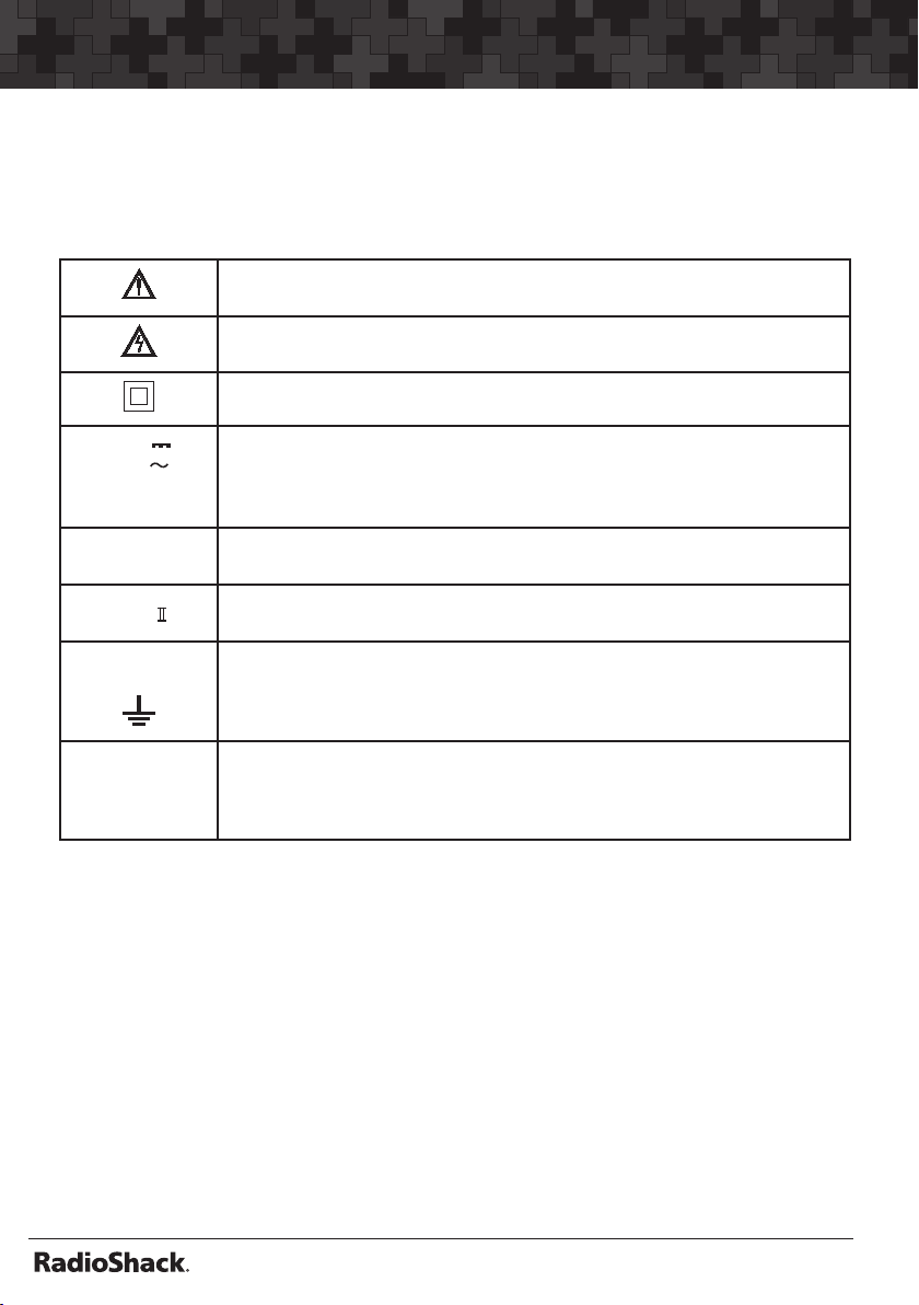
Radio Shack 22-812A User manual

Thank you for purchasing your 46-Range • PC46-Range • PC Interface Digital Multimeter from
RadioShack. The meter measures voltage, current, resistance, capacitance, and
frequency. It’s ideally suited for eld, lab, shop, and home applications. You can also
connect the meter to your computer and use the supplied software to log and graph
measurements. Please read this user’s guide before installing, setting up, and using your
new multimeter.
www.radioshack.com
22-812A
46-Range • PC Interface
Digital Multimeter
What’s Included
Digital Multimeter Test Leads (2) RS-232 Cable
Rubber Boot CD-ROM Fuse F500mA/250V (2)
Fuse F12A/250V (2) User’s Guide

2
MASTER BKGRD 6-26-07
Contents
MASTER BKGRD 6-26-07
Safety Precautions ............................................................................ 4
Special Panel Markings.........................................................................................5
Care and Maintenance ..........................................................................................5
A Quick Look at Your Meter ............................................................... 6
Preparation ....................................................................................... 8
Installing the Battery .............................................................................................8
Replacing the Fuses ..............................................................................................8
Basic Operation and Features............................................................ 9
Testing the Display ................................................................................................ 9
Using the Stand .....................................................................................................9
Connecting Test Leads...........................................................................................9
Using Power Lock ...................................................................................................9
Using Monitor ...................................................................................................... 10
Range Selection ................................................................................................. 10
Taking Measurements ..................................................................... 11
Taking Relative M./easurement........................................................................ 11
Displaying Temperature .................................................................................... 11
Measuring DC/AC Voltage ................................................................................. 12
Measuring DC/AC Current ................................................................................. 12
Measuring Resistance ....................................................................................... 13
Measuring Capacitance ..................................................................................... 14
Checking Continuity ........................................................................................... 14
Checking Diodes ................................................................................................. 15
Measuring Logic ................................................................................................. 15
Measuring Frequency/Duty Cycle/Pulse Width ............................................. 16
Measuring AC/DC Voltage Frequency .............................................................. 16
Measuring hFE .....................................................................................................17

MASTER BKGRD 6-26-07
3
MASTER BKGRD 6-26-07
Contents
Using the Meter With a Computer ................................................... 18
System Requirement .......................................................................................... 18
Installing the Meter’s Software/Hardware ..................................................... 18
Conguring/Using the Meter and Software .................................................... 18
Specifications ................................................................................. 20

4
MASTER BKGRD 6-26-07
Safety Precautions
MASTER BKGRD 6-26-07
Read and follow these safety precautions.
•Never apply voltages to the meter that exceed the limits given in theNever apply voltages to the meter that exceed the limits given in the
the input jacks and ground.
•Use extreme caution when working with voltages above 100V. AlwaysUse extreme caution when working with voltages above 100V. Always
disconnect power from the circuit you are measuring before you connect test
leads to high-voltage points.
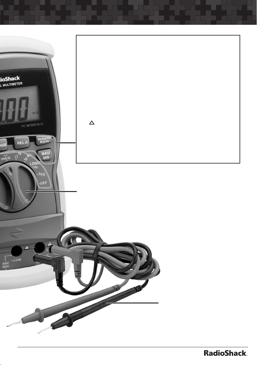
•Never connect the test leads to a voltage source when you set the meter’s
function dial to / , / , LOGIC/Hz, /µA/A, or /mA/A.
•Always discharge any capacitors of the circuit under test before you attachAlways discharge any capacitors of the circuit under test before you attach
test leads.
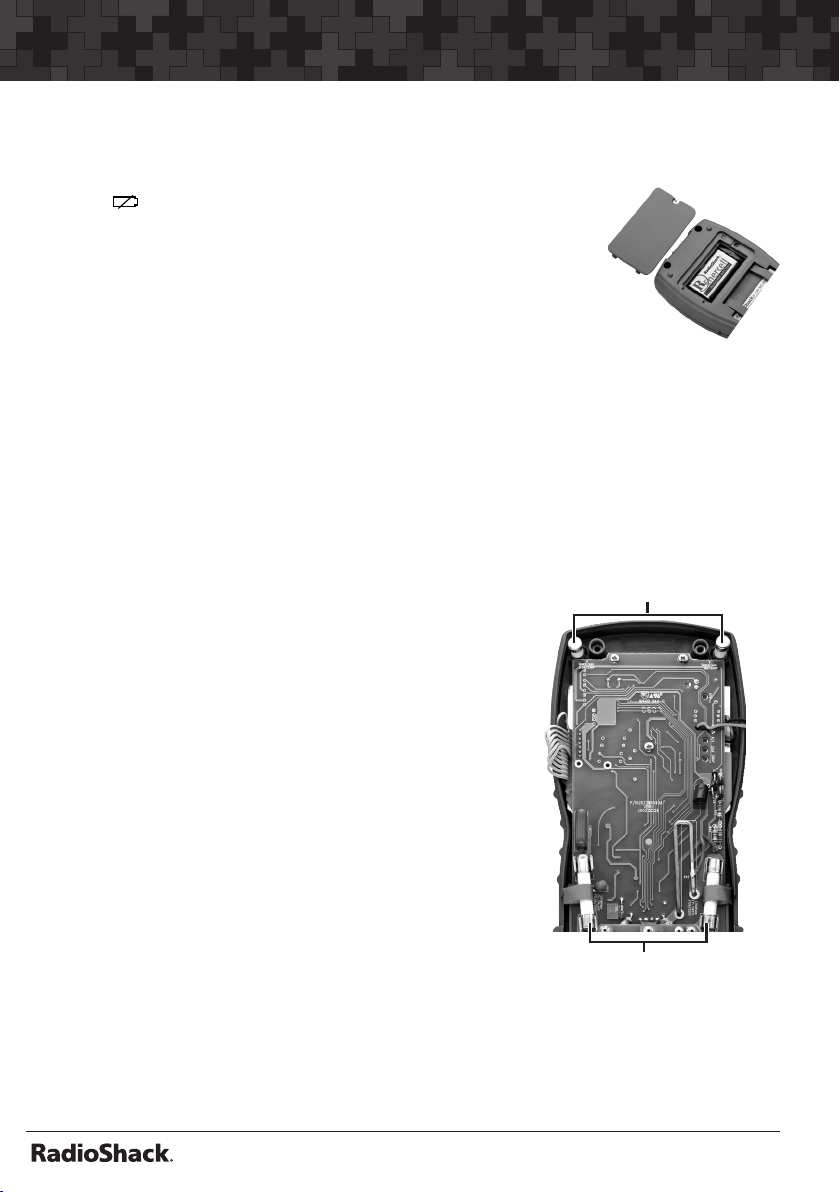
•Always turn off power and disconnect the test leads from the circuit you areAlways turn off power and disconnect the test leads from the circuit you are
testing before you replace the meter’s battery or fuse. Never operate theNever operate the
meter unless its back cover and battery cover are in place and fully closed.
•Never try to probe with both test leads at the same time or hold both test
leads in one hand.
•The test leads supplied with your meter are rated for 1000 volts. Use only test
leads of the same rating with the meter. You can order replacement leads
from your local RadioShack store.
•
might damage your meter.
•Because many AC/DC sets have a potentially hot chassis, be sure the top
materials.
• Your multimeter is designed primarily to measure household AC voltages.
Because of the dangers inherent in measuring three-phase circuits, WE
STRONGLY RECOMMEND YOU DO NOT USE THIS METER TO MEASURE
3-PHASE, LINE-TO-LINE VOLTAGE. If you still want to, put on protective
required before measuring. If you do not have this protection, DO NOT
MEASURE THESE CIRCUITS.
•
or moisture. For indoor use only.
•When you are not using the meter, always turn it off.
•
protection provided by the equipment may be impaired.

MASTER BKGRD 6-26-07
5
MASTER BKGRD 6-26-07
Safety Precautions
This meter is fully calibrated and tested. Under normal use, no further adjustment
should be necessary. If the meter requires repair, do not try to adjust it yourself.
Take it to your local RadioShack store.
Special Panel Markings
CAUTION: Risk of electric shock! Refer to the complete operating
instructions.
CAUTION: Be extremely careful when making high-voltage
measurements; DO NOT TOUCH TERMINALS OR PROBE ENDS.
The meter is protected by double insulation.
1 K V
750V
400mA
MAX
The maximum voltage that this meter can measure is 1000V DC or
400mA DC and AC.
+10A MAX
FUSED
The maximum current you can measure at this jack is 10 amps DC/AC.
This jack is fuse-protected.
CAT. This equipment is rated for INSTALLATION CATEGORY II (3600VA
max).
500V
MAX
To avoid electrical shock or instrument damage, do not connect the
common input terminal (–COM jack) to any source that exceeds 500
volts with respect to earth/ground.
WARNING:
Shock Hazard
if guard not
installed.
The sliding guard on the front of the meter protects against electrical
shock. Do not remove the guard.
Care and Maintenance
Keep the meter dry; if it gets wet, wipe it dry immediately and make sure that themake sure that the
meter is completely dry before using it. Use and store the meter only in normalUse and store the meter only in normal
temperature environments. Handle the meter carefully; do not drop it.
To keep the meter looking new, occasionally wipe it with a cloth slightly
dampened with water. Do not use harsh chemicals, cleaning solvents, or strong
detergents to clean the meter.

6
MASTER BKGRD 6-26-07
A Quick Look at Your Meter
MASTER BKGRD 6-26-07
ºC/ºF/ V – Displays temperature / measures DC volts.
dBm / V – Measures AC voltage in dBm or volts.
/ µA/A – Measures current.
/ mA/A – Measures current.
/ – Measures ohms and capacitance.
/ – Checks continuity and diodes.
LOGIC/Hz – Measures logic (HI/LO) / frequency.
hFE – Measures the gain of small-signal bipolar transistors.
OFF – Switches off the meter.
+ 10A MAX FUSED – Plug the red lead into this jack to
measure current higher than 400 mA.
Sliding Guard
WARNING: THE GUARD PROTECTS AGAINST ELECTRIC
SHOCK. DO NOT REMOVE IT.
Rubber Boot –– Protect the meter and store the test leads
using the clips on the back.
AUTO - Appears in the auto range mode. The meter
automatically enters the auto range mode when you turn
it on.

MASTER BKGRD 6-26-07
7
MASTER BKGRD 6-26-07
Function/Power dial
Rotate to turn the meter on/off. Rotate to select the
measurements, then press SELECT to choose the function.
SELECT – Press to toggle measurement options within a
function.
RANGE – Selects auto or manual ranging.
Press to enter the manual range mode and press to select
different ranges.
Hold down about 2 seconds to exit the manual range mode.
HOLD – Press to hold all indications on the display.
To cancel hold, press HOLD again or set the function dial to
another setting.
REL – Takes relative measurements.
Hz/DUTY/WIDTH – Measures frequency, duty cycle, and pulse
width.
MAX/MIN – Stores maximum and minimum readings.
Test leads

8
MASTER BKGRD 6-26-07
Preparations
MASTER BKGRD 6-26-07
Installing the Battery
Your meter requires one 9V battery (not supplied) for power.
When appears or the meter stops operating properly,
replace the battery.
1. Remove the rubber boot if it is attached.
2. Turn off your meter. Loosen the screw and remove theoff your meter. Loosen the screw and remove theyour meter. Loosen the screw and remove the
battery cover.
3. Snap a fresh 9V battery (not supplied) onto the terminals
of the battery clip in the battery compartment.
4. Replace the battery cover and secure it with the screw.
Battery Notes:
• Dispose of old batteries promptly and properly. Do not burn or bury them.Dispose of old batteries promptly and properly. Do not burn or bury them.
• If you do not plan to use the meter for a month or more, remove the battery. Batteries
can leak chemicals that can destroy electronic parts.
Replacing the Fuses
If the meter does not work, replace one or both
of the fuses. The spare 500mA, 250V ceramic fuse
and a 12A, 250V ceramic fuse are inserted in the
plastic holders inside the meter’s cabinet near the
top of the meter.
1. Turn off the meter and disconnect the test
leads.
2. Use a Phillips screwdriver to loosen the screws
from the back cover and gently pull apart the
case.
3. Pull the red ribbon to pop out the fuse.
4. Remove the spare fuse from the plastic holder
and insert it into the fuse holder through the
loop of the attached ribbon. Check the rating
of the fuse carefully and choose the proper one.
5. Replace the back cover and secure it with the screws.
Spare fuses
Fuses in red ribbons

MASTER BKGRD 6-26-07
9
MASTER BKGRD 6-26-07
Basic Operation and Features
For the most accurate reading, the temperature should be between 65º and 83ºF
Testing the Display
To test the meter’s display, turn off the meter, then hold down HOLD while turning
on the meter. The meter turns on and all segments on the display appear. Release
HOLD to end the test.
Using the Stand
surface for easier viewing.
Connecting Test Leads
Remove the plastic plugs before using your test leads.
Slide up the guard on the front of the meter if necessary. Plug the black test lead’s
right-angled end into –COM (common), then plug the red test lead’s right-angled
end into +V.Ω.mA. If you want to measure current higher than 400mA, plug the red
test lead’s right-angled end into +10A MAX instead of +V.Ω.mA.
WARNING:
• Although the test leads are rated for 1000 volts, the maximum rating of this meter is
• The meter sounds a warning tone when you set it to measure anything except current
and you connect a test lead to +10A MAX. This reminds you not to touch the circuit
with the test leads.
Using Power Lock
Your meter automatically turns off about 30 minutes when left unattended. Press
any button to turn the meter back on. Follow these steps to set the meter so it
does not turn off automatically.
1. Turn off your meter.
2. Hold down HOLD and SELECT simultaneously, then turn on the meter. PLoc
appears until you release both buttons.
To reactivate the meter’s auto power off function, turn off the meter then turn it
back on.

10
MASTER BKGRD 6-26-07
Basic Operation and Features
MASTER BKGRD 6-26-07
Using Monitor
The meter’s monitor feature displays the minimum or maximum value measured
and stores those values. If the meter measures a value higher than the stored
maximum value or lower than the stored minimum value, it updates the stored
value with the new value. The meter automatically sets itself to manual mode and
disables auto power off when you use it to monitor.
1. Set the meter to any function except ºC/ºF, dBm, , , LOGIC, or hFE.
2. Connect the test leads to the circuit.
3. Press RANGE to select a suitable range for monitor measurement.
4. Press MAX/MIN to record the maximum and minimum values. Max appears.
Press MAX/MIN to read the currently selected maximum value (when Max
appears) or minimum value (when Min appears).
5. To pause monitoring, press HOLD. Hold appears. To continue monitoring,
press HOLD again. Hold disappears.
To exit monitor mode, press MAX/MIN for more than 2 seconds. Max or Min
disappears.
Note: When the meter is set to its voltage or current function and the input is out of the
setting’s range, OF appears and Max or Min
Range Selection
Set the meter to the different measurement ranges. The unit of measure that
appears on the display shows the currently set range. Note the position of the
decimal. If 0.000 V appears, the meter is set to measure less than 4 volts. If
0000V appears, the meter is set to measure up to 1000 volts.
Read the range in volts, ohms, capacitance, or amps as indicated by the position
of the decimal point.
Range Display Range Display Range Display
400 mV ddd.d mV 4 mA d.ddd mA 400 kΩddd.d kΩ
4 V d.ddd V 40 mA dd.dd mA 4 MΩd.ddd MΩ
40 V dd.dd V 400 mA ddd.d mA 40 MΩdd.dd MΩ
400 V ddd.d V 4 A d.ddd A 4 nF d.ddd nF
1000 V DC
dddd V 10 A dd.dd A 40 nF dd.dd nF
400 Ωddd.d Ω400 nF ddd.d nF
4 kΩd.ddd kΩ4 µF d.ddd µF
400 µA ddd.d µA 40 kΩdd.dd kΩ40 µF dd.dd µF

MASTER BKGRD 6-26-07
11
MASTER BKGRD 6-26-07
Taking Measurements
Taking Relative Measurement
reference using the REL button.
Use zero offset as reference
1. Set the meter to any function except ºC/ºF, dBm, , , LOGIC, or hFE.
2. Disconnect test leads for capacitance, or touch the test leads together for
3. When you see the reading, hold down REL . Rel appears.
4. Take a measurement. You will get the actual value of the measured
component.
Use baseline as reference
1. Set the meter to any function except ºC/ºF, dBm, , , LOGIC, or hFE.
2. Press RANGE to select a suitable range for relative measurement if necessary.
3. Connect the test leads to the component whose measurement you want to
use as a baseline.
4. When you see the reading, hold down REL . Rel appears. The meter sets
to manual range.
5. Take a measurement. You will get the relative value of the measured
component to the baseline. If the measured value is lower than baseline, the
meter will show a negative relative value.
To reset a relative measurement, press REL again or set the function dial to
another setting.
Displaying Temperature
You can use an optional thermocouple module (not supplied) to measure
temperature with your meter.
WARNING: Do NOT use the thermocouple to measure objects when the voltage
is above 30 V RMS and 42.4 V peak or 60V DC.
1. Set the function dial to ºC/ºF/ V.
2. Unplug both test leads from the meter, plug the thermocouple’s common
plug into –COM (common), then plug the thermocouple’s +V plug into
+ V.mA.Ω.
3. Press SELECT to select temperature measurement. Then press RANGE toto
toggle between Celsius and Fahrenheit,Celsius and Fahrenheit, Cor Fappears.
4. Touch the thermocouple’s sensor head to the object you want to test.

12
MASTER BKGRD 6-26-07
Taking Measurements
MASTER BKGRD 6-26-07
Measuring DC/AC Voltage
WARNING: Do NOT try to measure a DC voltage above 1000 volts or an AC
red, black, or blue in AC wiring circuits). If one lead is clamped to a hot wire and
you touch the meter’s other probe, you could receive an electric shock.
1. To measure DC voltage, set the function dial to ºC/ºF/ V and press SELECT
to select DC voltage measurement.
To measure AC voltage, set the function dial to dBm/Vand press SELECT
to select dBm or volts unit.
2. If the meter is set to automatic range control, the meter automatically moves
to the range that gives the best reading.
To set manual range control, press RANGE then change the range (if
necessary) by pressing RANGE.
3. Touch the test leads to the circuit you want to test.
Notes:
• When the meter is set to the 400mV range, OF continues to appear even after you
remove an over-range input signal. This is not a malfunction.Touch the test leads
together or connect them to a circuit, then OF disappears.
drop.
You can also follow steps 1-3 above to measure AC voltage superimposed on a
DC voltage source bias while ignoring the DC voltage, but never try to measurenever try to measuretry to measure
an AC voltage that is riding on a DC source bias where the peak AC voltage
exceeds 1000 V with respect to earth ground.
Measuring DC/AC Current
To measure DC/AC current, you must break the circuit and connect the test leads
to two circuit connection points. The connection must be in series with the circuit
under test.
WARNING:
• Never connect the test leads across a voltage source. Doing so can damage
the meter or the circuit under test. The maximum input limit for AC/DC current
measurement is 10A.
•If you do not know the amount of current in the circuit you are measuring, always
connect the red test lead to +10A MAX.

MASTER BKGRD 6-26-07
13
MASTER BKGRD 6-26-07
Taking Measurements
1. Rotate the function dial to /µA/A for 0.4/4mA and 4/10A ranges or /mA/A
for 40/400mA and 4/10A ranges, and press SELECT to measure AC current (~
appears) or DC current (~ disappears).(~ disappears)..
2. Power off the circuit under test and discharge all capacitors.
3. Plug the black test lead into -COM and the red test lead into the appropriate
jack. Connect the meter’s test leads in series with the circuit.
4. Apply power and read the current value. If the measurement is less than
400mA and the red test lead is connected to +10A MAX, power off the
circuit.
If your measurement exceeds the selected range, OF appears until the
measured current is reduced to the selected range.
5. Move the red test lead to + V.mA.Ω.
6. Rotate the function dial to /µA/A or /mA/A depending on the value you
measured in Step 4.
If you are measuring DC current and the current’s polarity is negative, - appears
before the value.
Measuring Resistance
1. Power off the circuit under test and discharge all capacitors.
2. Rotate the function dial to / and press SELECT until (ohm), K (kilohm),
or MΩ(megohm) appears.
3 Touch tht e test leads across the resistor, or remove one of the leads of the
component from its circuit and touch the test leads across the resistor.
Notes:
OF
appears when you measure resistance. This is normal.
• If you are measuring resistance of about 1MΩor more, the display might take a few
• To calculate and measure a very small resistance, touch the test leads together
to measure the meter’s internal resistance, and then substract this value from the
measurement. Refer also to “Taking Relative Measurements” on page 11.

14
MASTER BKGRD 6-26-07
Taking Measurements
MASTER BKGRD 6-26-07
Measuring Capacitance
The capacitance measuring circuit in your meter charges a connected capacitor
meter measures the amount of time it takes to discharge the capacitor.
1. Power off the circuit under test and discharge all capacitors.
2. Rotate the function dial to / and press SELECT until nF or µF appears.
3. Attach the red test lead to the positive side of the capacitor and attach
the black test lead to the negative side. Or, remove one of the leads of
the capacitor from its circuit and connect the test leads to the capacitor’s
matching (positive or negative) terminals. The measured value appears.
Notes:
• The voltages applied across electrolytic capacitors affect their measured value.
That is, a measurement taken with a low voltage will be lower than one taken with a
voltage near the capacitor’s voltage rating. Since this meter cannot use high voltage
to set the electrolyte, it cannot measure the absolute value of capacitance.
• For low-value capacitors, the measurement might be very close to the meter’s actual
input capacitance. Use the meter’s relative feature to measure low capacitance values.Use the meter’s relative feature to measure low capacitance values.measure low capacitance values.
• Capacitance measurement accuracy depends on the measurement method and
differs with different types of capacitors. The meter’s measurement is for reference
only.
Checking Continuity
You can use the meter to check for shorted or open electrical circuits.
1. Power off the circuit under test and discharge all capacitors.
2. Rotate the function dial to / and press SELECT until appears.
3. Touch the test leads across the circuit you want to measure.
Shrt
(meaning the circuit is continuous or shorted).
Open
greater than about 50 ohms (meaning the circuit is not continuous).

MASTER BKGRD 6-26-07
15
MASTER BKGRD 6-26-07
Taking Measurements
Checking Diodes
You can check diodes, transistors, and other semiconductors for opens, shorts,
and normal operation, and determine the forward voltage and polarity for diodes.
You can also check LEDs.
1. Power off the circuit under test and discharge all capacitors.
2. Rotate the function dial to / and press SELECT. appears.
3. Connect the test leads to the device you want to check, or remove one of
the leads of the component from its circuit and connect the test leads to the
4. Reverse the test leads and note the second reading.
If one reading shows a value and the other is overrange (OF appears) the device
is good. If OF appears during both readings, the device is open. If both values are
Notes:
• When you test a silicon-type semiconductor, the values might vary depending on the
temperature.
• The values that appear during a diode check show the actual forward voltage (2.0V
max). If the voltage exceeds 2.0V, OF appears. The meter cannot check this diode.
• To check polarity of an unmarked diode: Connect the test leads to the two
sides of the diode. Measure and note the voltage. Then, reverse the test
leads, measure and note the second reading. The side of the diode where
the meter shows a higher voltage using the red test lead is the anode (+)
side. The side of the diode where the meter shows OF using the red test lead
is the cathode (–) side.
Measuring Logic
WARNING: Do NOT apply more than 5 V DC between terminals. This could
damage the meter or the circuit being tested.
1. Rotate the function dial to LOGIC/Hz and press SELECT once. LO appears.
2. Connect the test leads to the device you want to check.
LO appears if the logic is low (the voltage is lower than 1.0V). Hi appears if the
logic is high (the voltage is higher than 2.0V) The actual voltage appears if the
logic is between 1 and 2 V.

16
MASTER BKGRD 6-26-07
Taking Measurements
MASTER BKGRD 6-26-07
Measuring Frequency/Duty Cycle/Pulse Width
should not be larger than 10V peak.
1. Rotate the function dial to LOGIC/Hz and press SELECT until Hz, KHz, or
MHz appears.
Otherwise, press Hz/DUTY/WIDTH to select duty cycle function (function (% appears)
or pulse width function (µpulse width function (µµSor mS appears).
2. If you are measuring frequency, press RANGE if necessary to select manual
range then press RANGE until the range you want appears.
3. Connect the black test lead to a ground reference for the signal, and connect
the red test lead to the signal source.
Measuring AC Voltage/AC Current Frequency
The meter can measure the frequency of an AC voltage, with or without a DC
source bias.
WARNING: To avoid electrical shock and damage to the meter, never try to
RMS.
1. If you are measuring AC voltage with a DC source bias, set the function dial to
dBm / V. Otherwise, set the function dial to ºC/ºF/ V.
To measure AC current frequency, rotate the function dial torotate the function dial to / µA/A for
0.4/4mA and 4/10A ranges or / mA/A for 40/400mA and 4/10A ranges.
2. To select the frequency function, press Hz/DUTY/WIDTH until Hz, kHz, or
MHz appears.
3. To select the duty cycle or pulse width function, press Hz/DUTY/WIDTH until
%appears (to select duty cycle) or until µS or mS appears (to select pulse
width).
4. If %, µS, or mS appears and you want to select the frequency function again,
press Hz/DUTY/WIDTH until Hz, kHz, or MHz appears.
5. Connect the test leads to the device you want to check.

MASTER BKGRD 6-26-07
17
MASTER BKGRD 6-26-07
Taking Measurements
Notes:
• If the function dial is set to dBm / V and you want to set the meter for maximum
sensitivity when measuring a new signal, press SELECT to select the ACV function
then press Hz/DUTY/WIDTH to select the frequency function.
• To change back to ACV measurement, press SELECT once then press SELECT again
to select the AC V display mode (dBm or volts). PressPress SELECT twice to set the meter
back to the AC A measurement function.
• If the meter is set to measure current, it cannot measure the frequency of a signal with
DC bias.
Measuring hFE
You can use the meter to measure the DC gain of small-signal, bipolar transistors
in the hFE range of 1000.
CAUTION: To avoid damaging the meter, do not try to check a transistor if you do
not know its type and pinout.
1. Set the function dial to hFE.
2. Unplug both test leads from the meter, then
slide down the guard on the front of the
meter.
3. Insert the transistor you want to check into
the hFE socket, matching the pinout of the
transistor with the labels on the socket. The
transistor’s value appears.
hFE Socket - Insert a transistor
to check gain.

18
MASTER BKGRD 6-26-07
Using the Meter With a Computer
MASTER BKGRD 6-26-07
You can connect your meter to a computer, letting you conveniently monitor,
record, and log data over a long period of time. You can even use your meter to
display oscilloscope information on your computer. For example, you can record
changes in temperature in a refrigerator or voltage changes in a circuit over a long
period of time.
System Requirement
Windows®XP, Windows ME, Windows 2000, Windows 98 or Windows 95, with all
of the following:
• VGA or SVGA video adapter
• at least 32 MB RAM
• Microsoft-compatible mouse
Installing the Meter’s Software and Hardware
1. Turn on your computer and start the installed Windows operating system.
2. Insert the software CD into your CD-ROM drive.
The CD starts automatically. If it does not,
browse to your CD-ROM drive and openopen
setup.exe.
your computer.
4. Connect one end of the supplied RS-232 cable
to the jack on top of the meter, then connect
the other end to your computer’s serial port. The
Configuring and Using the Meter and Software
the Meter View software so
that they can work with each other.can work with each other.
1. Click Start, Programs, then Meter View on your computer. The Meter View
software starts.
2. Turn on your meter. Then hold down SELECT and RANGE together. RS232
appears.
3. On your computer, select the COM port where you connected the meter by
pulling down Option then COM Port, then clicking COM1, COM2, COM3, or
COM4.
RS-232 Connector

MASTER BKGRD 6-26-07
19
MASTER BKGRD 6-26-07
Using the Meter With a Computer
4. Then click the iconThen click the iconThen click the iconclick the icon , or pull down Run then click Start to set up the meterset up the meter
to work with your computer. Data is transmitted from your meter to your
computer. The display you see on the meter also appears on your computer.
Notes:
• If you select the wrong COM port, an error message appears. Repeat step 3 to select
the correct COM port.
• If the Meter View software stops communicating with the meter, check the connection
between the meter and the computer and make sure RS232 still appears on the
meter’s display.
Start,
Programs, Meter View, then select Help.

20
MASTER BKGRD 6-26-07
Specifications
MASTER BKGRD 6-26-07
DC VOLTS (Maximum Measurement: 1000V)
400mV ..........................................................................
4V to 40V .....................................................................
400V ..............................................................................
1000V ...........................................................................
AC VOLTS
Calibrated, AC Coupled)
400mV...........................................................................
4V to 40V .....................................................................
400V .............................................................................
.............................................................................
dBm ACCURACY
......................................................................................................
DC CURRENT (Maximum Measurement: 10A)
400µA, 40mA, 4A .........................................................
4mA, 400mA.................................................................
10A ...............................................................................
AC CURRENT (Average Responds, RMS Calibrated, 10A Maximum, DC Coupled)
400µA, 40mA, 4A .........................................................
4mA, 400mA.................................................................
10A ...............................................................................
RESISTANCE
400Ω.............................................................................
4kΩ, 40kΩ, 400kΩ.......................................................
4.0MΩ...........................................................................
40MΩ...........................................................................
CAPACITANCE
4nF ...........................................................................
40nF .........................................................................
400nF, 4µF, 40µF ..........................................................
Note
except 4.0nF range from 0.5nF to full scale.
PULSE WIDTHS
1µS to 90mS (at +5/–0V square wave):...........................
Table of contents
Other Radio Shack Multimeter manuals

Radio Shack
Radio Shack 2200087 User manual

Radio Shack
Radio Shack 22-812 User manual

Radio Shack
Radio Shack 22-812 User manual

Radio Shack
Radio Shack 22-168A User manual

Radio Shack
Radio Shack 22-178 User manual

Radio Shack
Radio Shack 22-174A User manual

Radio Shack
Radio Shack 22-218 User manual

Radio Shack
Radio Shack 22-602 User manual

Radio Shack
Radio Shack 22-813 User manual

Radio Shack
Radio Shack 22-812 User manual