Radio Shack 2200813 User manual

2200813
User’s Guide
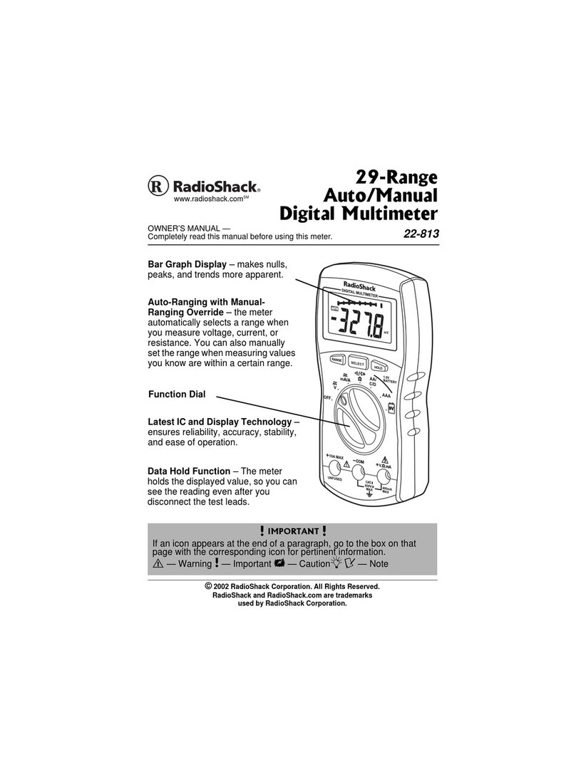
29-Range Digital Multimeter
Thank you for purchasing your 29-Range
Digital Multimeter from RadioShack. Please
read this user’s guide before installing, setting
up, and using your new multimeter.

2
Contents
Package Contents ...................................3
Features....................................................3
Care and Service ......................................3
Safety Precautions....................................4
Special Panel Markings ............................7
Install the Batteries...................................8
Connect the Test Leads............................8
Basic Operation....................................9
Selecting Ranges......................................9
Measuring DC/AC Voltage.....................10
Measuring AC Voltage Riding on a DC
Source Bias .............................................11
Measuring DC/AC Current.....................12
Measuring Resistance.............................13
Checking Continuity...............................14
Checking Diodes ....................................14
Checking Batteries .................................16
Additional Information .......................18
Replacing the Fuse.................................18
Auto Power Off ......................................19
Testing the Display .................................19
Specifications..........................................20
Limited Warranty ....................................22

3
Package Contents
• 29-RangeDigitalMultimeter • TestLeads(2)
• SpareFuse(inthecase) • User’sGuide
Features
• Measures voltage, current and resistance
• Auto-ranging with manual-ranging override
• Diode test
Care and Service
• Keep your meter dry and clean. If it gets wet or dirty, wipe it dry or clean immediately
with a cloth lightly dampened with water. Do not use harsh chemicals, cleaning solvents,
or strong detergents to clean the meter.
• Useandstorethemeterinnormaltemperatureenvironmentsonly.Handleyourmeter
carefully. Do not drop it.
• Modifying or tampering the meter’s internal components can cause malfunction and
might invalidate its warranty. If your meter is not performing as it should, take it to your
local RadioShack store for assistance.

4
Safety Precautions
• Do not use the meter if you are unfamiliar with electric circuits and testing procedures.
• To avoid electric shock, disconnect both test leads from the circuit under testing before
you replace the batteries and fuse.
• Do not operate the meter until the batteries are properly installed and the back cover
and battery compartment cover are in place and secured.
• Useextremecautionwhenworkingwithvoltagesabove30VRMSand42.4Vpeakor60V
DC. Always disconnect power from the circuit you are measuring before you connect test
leads to high-voltage points.
• Never connect to a voltage source when you select the diode check, continuity function,
resistance measurement, or any of the battery test or current measurement functions.
• Always discharge any capacitors of the circuit under test before you attach test leads and
always turn off power and disconnect the test leads from the circuit before replacing the
meter’s batteries or the fuse.
• Because many AC/DC sets have a potentially hot chassis, be sure the top of your
workbench and the floor underneath it are made of nonconductive materials.
• If you connect one test lead to a hot wire first and touch the other test lead tip, you
could receive an electric shock.

5
• Thetestleads(blackandred)suppliedwithyourmeterareratedfor1000voltsbutdo
nottrytomeasureanyvoltagegreaterthan600voltsDC/600voltsRMSAC.Useonly
test leads of the same rating as the meter.
• Your multimeter is designed primarily to measure household AC voltages. Because of
the dangers inherent in measuring three-phase circuits, WESTRONGLYRECOMMEND
YOUDONOTUSETHISMETERTOMEASURE3-PHASE,LINE-TO-LINEVOLTAGE.
If you still want to, put on protective clothing – a face shield and fireproof gloves and
upper body protection is required before measuring. If you do not have this protection,
DONOTMEASURETHESECIRCUITS.
• Toreducetheriskofreorshockhazard,donotexposethisproducttorainormoisture.
For indoor use only.
• If this equipment is used in a manner not specified by the manufacturer, the protection
provided by the equipment may be impaired.
• Forthemostaccuratereading,thetemperatureshouldbebetween65°Fand83°F(18°C
to28°C),withamaximumof75%relativehumidity.

6
Range – Press to select ranges.
AUTO – Auto range mode.
SELECT – Toggle measurement options within a function.
HOLD – Press to hold all indications on the display.
Function/Power dial
Turn the meter on/off or select the type of measurement:
•V – Measures DC/AC voltage.
•mA/A – Measures amperage: DC40/400mAandAC
40/400mA;DC4/10AandAC4/10A
• Ω– Measures resistance and checks continuity/
diodes.
•AA/C/D, AAA, 9V – Test specific battery types.
Bar Graph Display –8segmentsrepresentunitsforthe
selected function.

7
Setup
Special Panel Markings
Themaximumvoltagethatthismetercanmeasureis600VRMSACor600V
DC. To avoid electric shock and damage to the meter, do not connect the
twoinputterminals(-COM and +V.Ω.mA)toanysourcethatexceeds600
volts with respect to ground.
400mA
MAX
Themaximumcurrentthatthismetercanmeasureatthisjackis400mADCor
AC.
Caution: RISKOFELECTRICSHOCK!Refertothecompleteoperating
instructions.
Caution: Beextremelycarefulwhentakinghigh-voltagemeasurements.DO
NOTTOUCHTERMINALSORTESTLEADENDS.
CAT II ThisequipmentisratedforinstallationcategoryII(3600VAmax.).
10A MAX.
UNFUSED
Themaximumcurrentyoucanmeasureatthisjackis10ampsDC/AC.This
jackisnotfuse-protected.
The meter is protected by double insulation.
nNote: The UL mark does not indicate that this product has been evaluated by
Underwriters Laboratories for the accuracy of its readings.
600V
MAX

8
Setup
Install the Batteries
Before installing batteries, turn off the multimeter and disconnect the
testleads.InstallthreeAAAbatteries(notincluded),matchingthe
polaritysymbols(+and-)markedinside.When appears, replace
the batteries.
• Disposeofbatteriespromptlyandproperly.Donotburnorbury
them.
• Useonlyfreshbatteriesoftherequiredsizeandtype.
• Ifyoudonotplantousethemeterforamonthormore,remove
the batteries. Batteries can leak chemicals that can damage electronic parts.
Connect the Test Leads
1. Remove the rubber caps from the test leads.
2. Plug the black lead into the –COM jackandthe
red lead into the +V.Ω.mAjack.Tomeasurecurrent
greaterthan400mA,plugtheredtestleadinto
+10A MAX.
nNote: After connecting to the +10A MAXjacktomeasureanythingexceptcurrent,a
buzzerremindsyounottotouchthetestleadstothecircuit.

9
Operation
Range Display
400mV ddd.d mV
4V d.ddd V
40V dd.dd V
400V ddd.d V
600V ddd V
40mA dd.dd mA
400mA ddd.d mA
4A d.ddd A
10A dd.dd A
400Ωddd.d Ω
4kΩd.ddd kΩ
40kΩdd.dd kΩ
400kΩddd.d kΩ
4MΩd.ddd MΩ
40MΩdd.dd MΩ
“d” denotes any digit from
0to9.
Basic Operation
Selecting Ranges
Setthemetertoameasurementrange;theunitofmeasure
appearsonthedisplay.Forexample,mVappearsinthe400
mVrange.
Note the position of the decimal:
• If0.000Vappears,themeterissettomeasurelessthan
4volts.
• If000Vappears,themeterissettomeasureupto600
volts.
Read the range in volts, amps, or ohms as indicated by the
position of the decimal point.

10
Operation
wCaution:
• IfyouaremeasuringvoltageorcurrentwhenOF(overow)appears,immediately
disconnect the test leads from the circuit.
• Whenmeasuringhigh-voltagecircuits,donotpositionbothtestleadsatonce.Connect
theblacktestleadrsttothecircuit’sneutralorgroundlead.Then,usingonehand,
probe for voltages with the other test lead. This helps prevent accidentally touching a
hot wire.
Measuring DC/AC Voltage
DONOTtrytomeasurevoltagesabove600VDC/AC(RMS).
1. Set the function dial to V.
2. Press SELECT to select DC or AC. appears for AC voltage measurement.
3. Touch the black test lead to the circuit.
4. Touch the red test lead to the circuit.
If the meter is set to manual range and you measure an overrange input, OF will display. The
meter will return to standby mode when you remove the input.

11
Operation
Measuring AC Voltage Riding on a DC Source Bias
Warning: Toavoidinjuryordamagetoyourmeter,nevertrytomeasureanACvoltage
onaDCsourcebiaswherethepeakACvoltageexceeds100Vwithrespecttoearthground.
1. Set the function dial to V(DC voltage). Measure the DC voltage first to ensure that it
doesnotexceed100V.
2. Disconnect power from the circuit.
3. Press SELECT(ACmode). appears.
4. Connect the black test lead to the circuit’s neutral/ground lead.
5. Connecta0.1microfarad/100Vmylarcapacitorinserieswiththevoltagesource’s
positive terminal and the red test lead.
6. Restore circuit power and read the voltage.
7 Poweroffthecircuit;thendisconnectthecapacitor.

12
Operation
Measuring DC/AC Current
1. Disconnect power from the circuit and discharge all capacitors.
2. Rotate the function dial to mA/A .
3. Press SELECT to select DC or AC. appears for AC current measurement.
4. Break the circuit and connect the black test lead to one of the two connection points.
5. Plug the red test lead into + 10A MAX.Tomeasurecurrentlessthan400mA,plugthe
red test lead to +V.Ω.mA jack.DoNOTmeasurecurrentgreaterthan10A.
6. Connect the red test lead to the connection point on the broken circuit.
7. Power the circuit and read the results.
nNote:
• The+V.Ω.mA jackisisfuse-protected.Ifthemetercannotmeasurein40/400mA
ranges,checkandreplacethefuse.
• Ifthecurrent’spolarityisnegative,– appears before the value.

13
Operation
Measuring Resistance
1. Disconnect power from the circuit and discharge all capacitors.
2. Rotate the function dial to Ω.
3. Repeatedly press SELECT to select Ω, KΩ, or MΩ.
4. Connect the black test lead to one component lead.
5. Connect the red test lead to the other component lead, or remove one component lead
from its circuit and touch the test leads across the component.
nNote:
• Ifnoresistanceisconnectedacrossthetestleads(meaningresistanceisinnite),orthe
valueundertestingexceedstherangeyouset,O.F appears. This is normal.
• Ifyouaremeasuringresistanceofabout1MΩormore,thedisplaymighttakeafew
secondstostabilize.Thisisnormal.

14
Operation
Checking Continuity
You can check for shorted or open electrical circuits.
1. Disconnect power from the circuit and discharge all capacitors.
2. Rotate the function dial to Ω.
3. Repeatedly press SELECT until appears.
4. Connect the black test lead to one end of the circuit and the red lead to the other end.
• Open appearsifthecircuitresistanceisgreaterthanabout50±10ohms(meaningthe
circuitisnotshorted).
• Shrtappearsandthebuzzersoundsifthecircuitresistanceislessthanabout50±10
ohms(meaningthecircuithaslowohmageorisshorted).
Checking Diodes
You can check diodes, transistors, and other semiconductors for opens, shorts, and normal
operation. You can also determine the forward voltage and polarity for diodes and check diode
polaritywhenpositive(+)andnegative(–)sidesarenotmarked.
1. Disconnect power from the circuit and discharge all capacitors.
2. Rotate the function dial to Ω.

15
Operation
3. Press SELECT until appears.
4. Connect the black test lead to the cathode or a component pin.
5. Connect the red test lead to the anode or the other component pin, or remove one
of the leads of the component from its circuit and touch the test leads across the
component. Then note the first reading.
6. Reverse the test leads and note the second reading.
• Ifonereadingshowsavalueandtheotherisoverrange(.OFappears),thedeviceis
good.
• If OF appears during both readings, the device is open.
• If both values are very small or zero, the device is shorted.
nNote:
• Thevaluesformostsemiconductorsmayvarydependingonthetemperature.
• Thevaluesthatappearduringadiodecheckshowtheactualforwardvoltage(max.
3.0V).Ifthevoltageexceeds3.0V,O.F appears. This means the diode check cannot be
made using this meter.
• Check diode polarity: Connectthetestleadstothetwoendsofthediode.Measure
andnotethevoltage.Then,reversethetestleads.Thesideofthediodewherethe
meter shows a higher voltage using the red test lead is the anode (+) side. The side of
the diode where the meter shows OF using the red test lead is the cathode (–) side.

16
Operation
Checking Batteries
The meter can accurately check the following batteries under designated load conditions:
• 1.5VC
• 1.5VD
• 1.5VAA
• 1.5VAAA
• 9Vbatteries.
1. Rotate the function dial to your desired setting.
2. Connecttheblacktestleadtothebattery’snegative(–)terminal
3. Connecttheredtestleadtothebattery’spositive(+)terminal.
• If you connect the test leads in reverse polarity, –appears on the left side of the display.
Usethistabletodeterminethebattery’scharge.

17
Operation
Battery Range Display Action
AAA/AA/C/D
9V
<0.010volts
No value appears.
Replace the battery.
<0.10volts
<1volt
VoltageandBad appear.
<6volts
1–1.1volts
VoltageandGood appear.
The battery is good.
6-6.6volts
1.1–1.5volts
6.6-9volts
>1.5volts
The battery is full.
> 9 volts
> 2 volts
.OF appears
>11volts

18
Additional Info
Additional Information
Replacing the Fuse
If the meter does not operate or “FUSE Bad”
appears on the display, you might need to
replacethefuse.Usethesuppliedspare
fuseora5×20mm,500mA,250VCooper
BussmannS501seriesfuseorequivalentsand
filled ceramic fuse.
1. Turn off the meter and disconnect the test
leads.
2. UseaPhillipsscrewdrivertoopenthe
back cover of the meter.
3. Gentlypulltheredribbonwrapped
around the fuse to pop it out.
4. If the fuse is blown, discard it and save the red ribbon. Place the supplied spare fuse
into the ribbon, and insert the fuse into the fuse holder.
5. Replace the back cover.
nNote:Donotuseafusebrandorratingotherthantheonespeciedhere.Doingso
might damage your meter.
Fuse
Installed
Spare Fuse

19
Additional Info
Auto Power Off
Yourmeterconservespowerbyautomaticallyturningoffabout30minutesafterthelast
timeyouchangedasetting(evenifyouaretakingmeasurements).Themetershortbeeps
severaltimesandlongbeepsonceabout1minute,thenturnsoff.Pressanybuttonorselect
another function to turn it on.
To set the meter so that it does not turn off automatically, press and hold HOLD and
SELECT at the same time, as you turn on the meter. PLoc appears. When you release HOLD
and SELECT. PLoc disappears and PWR
Lock appears.
To reactivate the meter’s automatic power saving function, turn off the meter then turn it on.
PWR
Lock disappears.
Testing the Display
To test the meter’s display, hold down any button while turning on the meter. All segments
appear on the display. Release the button to end the test.

20
Additional Info
Specifications
DC VOLTS (MaximumMeasurement:600V)
400mV.................................................................................................... ±0.5%ofReading,±4inLastDigit
4V–40V–400V..................................................................................... ±0.8%ofReading,±4inLastDigit
600V ....................................................................................................... ±1.0%ofReading,±4inLastDigit
AC VOLTS (600VRMSMaximumat50/60Hz,Averageresponds,RMScalibrated,DCCoupled)
400mV,40V–400V–600V.................................................................... ±1.2%ofReading,±5inLastDigit
4V ........................................................................................................... ±0.8%ofReading,±5inLastDigit
DC CURRENT(MaximumMeasurement:10A)
40mA–400mA...................................................................................... ±1.2%ofReading,±4inLastDigit
4A–10A ................................................................................................ ±1.5%ofReading,±4inLastDigit
AC CURRENT(Averageresponds,RMScalibrated,10Amaximum,DCcoupled)
40mA–400mA...................................................................................... ±1.5%ofReading,±4inLastDigit
4A–10A ................................................................................................ ±2.0%ofReading,±4inLastDigit
RESISTANCE
400Ω – 4k – 40kΩ – 400kΩ – 4.0MΩ ................................................±1.2%ofReading,±4inLastDigit
40MΩ ...............................................................................................±2.0%ofReading,±4inLastDigit
BATTERY TEST
1,5VC/D/AA(150mA±10%loadcurrent);1.5VAAA(50mA±10%loadcurrent);9VBattery(10mA±10%
loadcurrent).......................................................................................... ±5.0%ofReading,±4inLastDigit
DIODE MODE
OpenCircuitVoltage......................................................................................................................<3.0VDC
Test Current............................................................................................................................0.8mA(Typical)
Table of contents
Other Radio Shack Multimeter manuals

Radio Shack
Radio Shack 22-812A User manual

Radio Shack
Radio Shack 22-812 User manual
Radio Shack
Radio Shack 22-602 User manual

Radio Shack
Radio Shack 22-812 User manual

Radio Shack
Radio Shack 2200087 User manual
Radio Shack
Radio Shack 22-178 User manual

Radio Shack
Radio Shack 22-813 User manual

Radio Shack
Radio Shack 22-812 User manual

Radio Shack
Radio Shack 22-174A User manual
Radio Shack
Radio Shack 22-218 User manual