www.SteamPoweredRadio.Com
Contents
Safety
Precautions
............................................................................4
Using
the
Meter
wl
i
th
a
Computer
...................................................
18
Special Panel Markings.........................................................................................5 System Requirement.....
..
.....................................................................
...
.........
..
18
Care and Maintenance ..........................................................................................5 Installing the Meter's Software/Hardware .....................................................
18
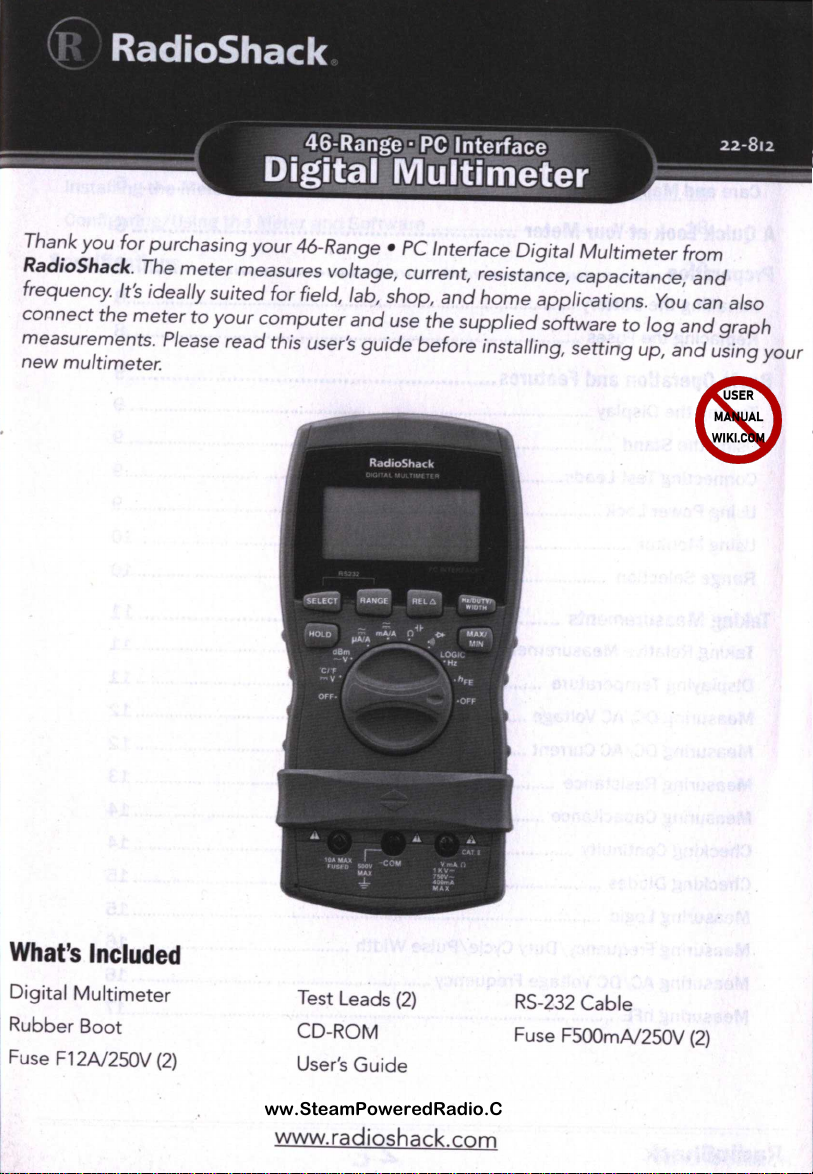
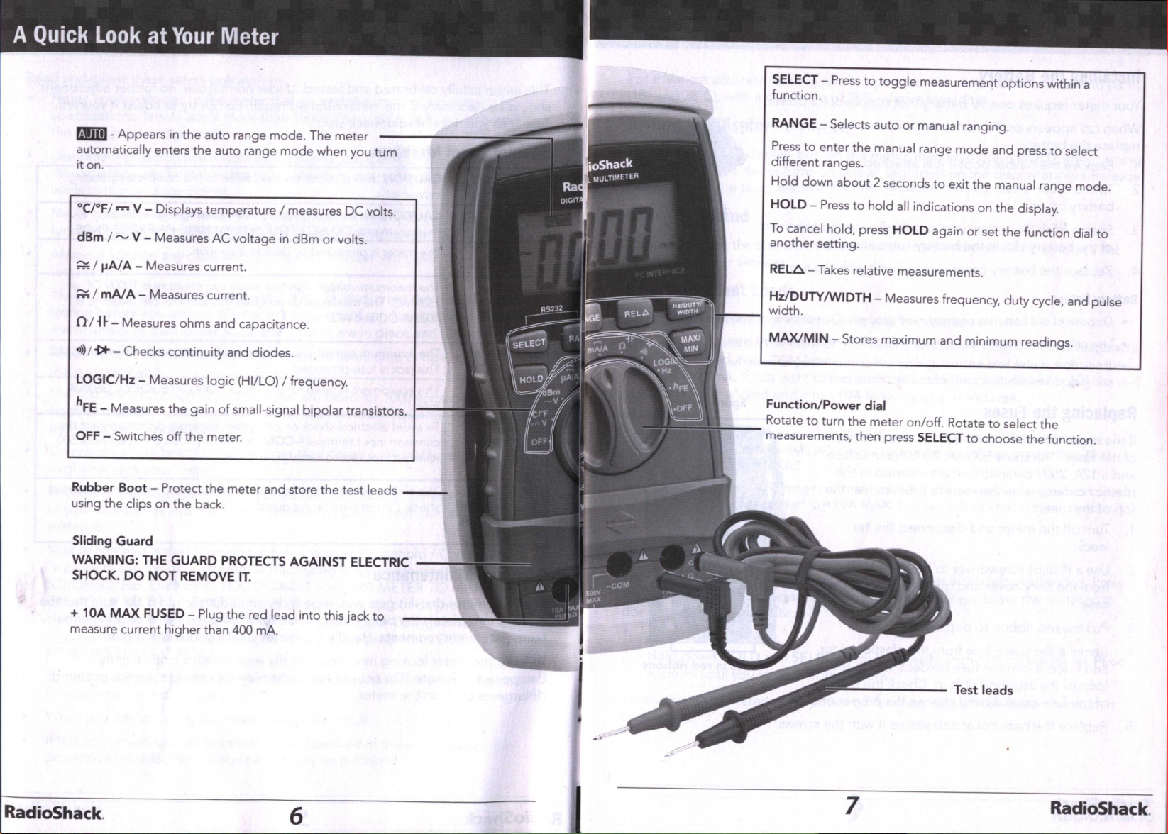
A
Quick
Look
at
Your
Meter
...............................................................6 Configuring/Using
the
Meter and Software .....................................
...
............
18
Preparation
.......................................................................................8
Specifications
..................................................................................20
Installing
the
Battery .............................................................................................8
Replacing
the
Fuses ..............................................................................................8
Basic
Operation
and
Features
............................................................9
Testing the Display................................................................................................ 9
Using the Stand .....................................................................................................9
Connecting Test Leads...........................................................................................9
Using Power Lock ...................................................................................................9
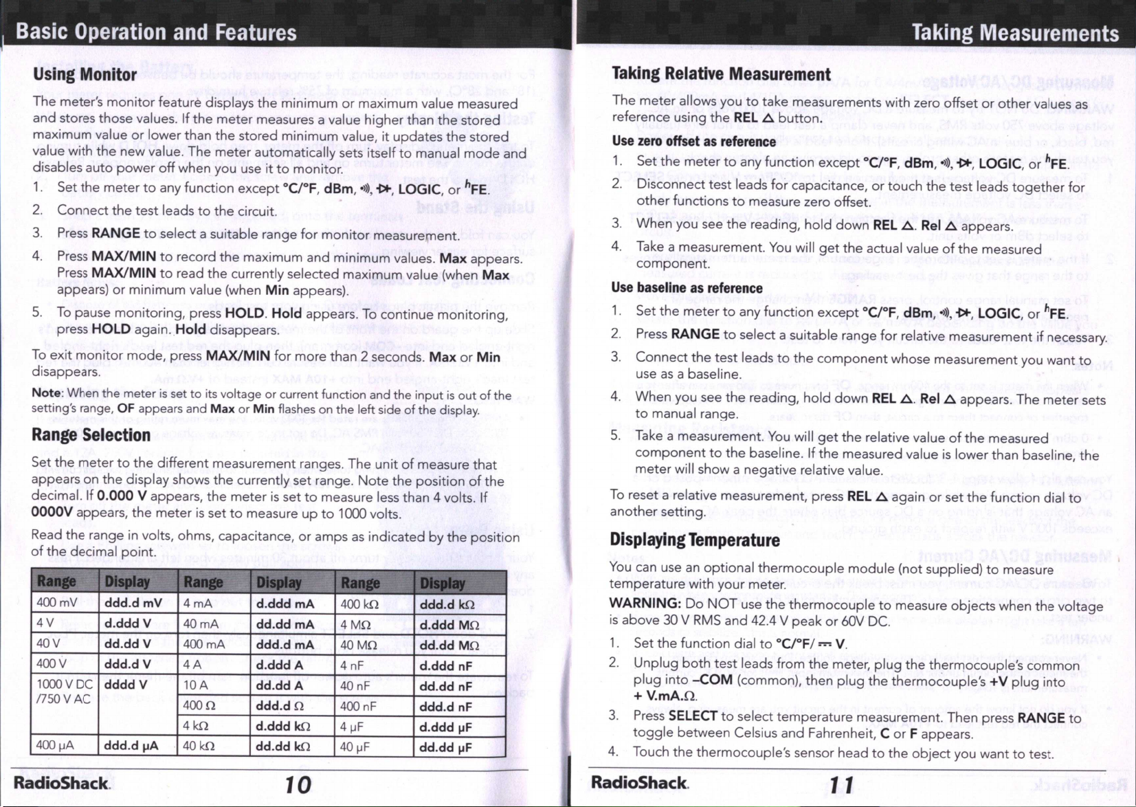
Using Monitor ......................................................................................................
10
Range Selection .................................................................................................
10
Taking
Measurements
.....................................................................
11
Taking Relative Measurement...........................................................................
11
Displaying Temperature ....................................................................................
11
Measuring DC/
AC
Voltage ......................................
..
.........................................
12
Measuring DC/
AC
Current .................................................................................
12
Measuring Resistance .......................................................................................
13
Measuring Capacitance ............................................................................
...
......
14
Checking Continuity ...........................................................................................
14
Checking Diodes .................................................................................................
15
Measuring Logic .................................................................................................
15
Measuring Frequency/Duty Cycle/Pulse Width .............................................
16
Measuring AC/DC Voltage Frequency ...........................................................
...
16
Measuring
hFE
..................................................................................................
..
.
17
RadioShack. 2 3 RadioShack.