manuals.online logo
Brands
  1. Home
  2. •
  3. Brands
  4. •
  5. Radio Shack
  6. •
  7. Recording Equipment
  8. •
  9. Radio Shack Modem I TRS-80 User manual

Radio Shack Modem I TRS-80 User manual

ttCMlKf mIKH7H
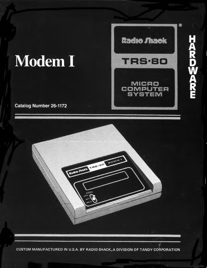
Modem I
Catalog Number 26-1172
MICRO
P^f^EHJIWtl —'IIHIIIII.
w?$
CUSTOM MANUFACTURED IN U.S.A. BY RADIO SHACKM ADIVISION OF TANDY CORPORATION
Introduction
The Modem Iis aself-contained, fsk (Frequency Shift Keying) telephone
interface. It enables your computer to communicate with other computers via
ordinary telephone lines. The Modem Iis compatible with all trs-80 models
(except Level Iversions of the Model Iand Model III) and with other rs-232 c
standard devices.
Its special features include:
•Sends/receives at 0-300 baud for compatibility with most time-shared
computer systems.
•Selectable originate/answer mode for operation in "remote" or "host"
terminal applications.
•Full duplex operation allows simultaneous communication between modems.
•Direct (non-acoustic) connection to phone lines helps ensure alow error rate.
•NORMal/CASsette switch lets you use rs-232-c equipped computers and trs-80
Model ILevel II computers which do not have an rs-232~c interface. Select
norm for rs-232-c use; cass for use with the cassette interface of Model I
Level II Computers. Cassette use requires optional/extra "Cassette-Comm"
software (Radio Shack Cat. No. 26-1139) and acassette cable (26-3009).
•Bell 103 compatible.
Note: When using the Cassette Comm software, communications will not be in
atrue full duplex mode. For further details, see the Cassette Comm instruction
manual.
Important Note
Before connecting your Modem Ito the phone lines, you must notify your
local telephone company of the:
Manufacturer: Radio Shack
Model: Modem I, #26-1172
USOC Number: RJ11C
FCC Number: AA099R-69525-DM-N
Ringer Equivalence Number (REN): 0.0B
This information also appears on the bottom of the Modem.
The Modem Imust not be connected to:
[x] Coin-operated phones
[x] Party-line phones
[x] Multiple-line phones
Modem IOwner's Manual: Copyright ©1981 Tandy Corporation. All rights reserved.
Installation
Modem/Telephone Connection
Figure 1shows the connection of aModem Ito telephone lines using the new
modular connectors. If your telephone has this type of connection, attach your
Modem Ias shown.
If your telephone has the older style four-prong connection (see Figure 2), you
will need an adapter which allows the Modem Ito be used in parallel with your
telephone. Radio Shack sells this type of adapter, Cat. No. 279-360.
If your telephone is wired directly to the wall as in Figure 3, you must contact
the telephone company and have them install modular connections. Be aware
however, that you will be charged for this service.
After connecting the telephone, make sure that the mode switch on the Modem
is off. Your telephone should be operating normally now.
AC Connection
Connect the ac adapter to the ac jack on the Modem's rear panel and to an
electrical wall outlet.
Note: Use only the supplied, UL-listed adapter. The use of any other adapter
could damage the Modem.
Modem/Computer Connection via
RS-232-C Interface
For most applications, you will use an rs-232-c equipped computer. Table 1
summarizes the cable and connection requirements for rs-232~c equipped
trs-80's. Using the table, select the appropriate connector for your computer.
Connect the computer's rs-232-c interface to the specified connection point on
the Modem.
TRS-80 Model Cable Connection Point
TRS-80 Modem I
Model 1, Level II 26-1145* Card-Edge
on Exp/Int
DB-25
"RS232C"
Model II 26-4403 DB-25
"CHANNEL A/B"
DB-25
"RS232C"
Model III 26-1408 DB-25
Serial I/O
DB-25
Color Computer 26-3014 DIN
Serial I/O
DIN
"RS232/CASS"
This is the RS-232-C interface board. The cable is included.
Table 1. RS-232-C Cable Identification and Connection
If your telephone hook-up looks like this:
3
1'
Connect like this:
Figure 1. Connection to Modular Phone Jacks.
If your telephone hook-up looks like this:
Connect like this:
M3
/
Adapter
Radio Shack
Cat. No. 279-360
(Refer to the text)
~-7\
Modem telephone cord
Figure 2. Connection to Four-Prong Jacks.
If your telephone hook-up looks like this:
Call the Telephone Company and request amodular telephone connection
like this:
Refer to Figure 1to make your new phone connection.
Figure 3. Connection to Wired Phone Jacks. (Requires
Phone Company Conversion)
Modem/Computer Connection via
Cassette Interface
Note: When using the Cassette Comm software, communications will not be in
atrue full duplex mode. For further details, see the Cassette Comm instruction
manual.
If you have aModel ILevel II computer which is not equipped with an rs-232-c
interface board, you may use the cassette interface of your computer for serial
communications with the Modem. To do this, you will need to buy the
"Cassette-Comm" software and the appropriate cable (Cat. Nos. 26-1139 and
26-3009, respectively).
Connect the cable to the tape connector on your computer and to the rs-232/cass
connector on the Modem.
Note: The Model III cassette circuitry cannot be used for serial communications
with the Modem.
Controls and Connectors
Refer to Figure 4. -
(l) mode Switch Selects either ORiGinate or ANSwer mode. Note: With the
Modem connected, your phones are available for conversational use only
when the mode switch is off. So be sure to select mode off when you are
not using the Modem.
©On Power Light Remains lit while the Modem is "on."
(3) CD. (Carrier Detect) Light Lights and remains lit while a"carrier tone" is
being received via phone lines from another modem.
(4) rs-232C Standard db~25 jack for connection to rs-232-c interface of Models
I, II and III.
(s) rs-232/cass This four-pin din jack allows connection to the rs-232-c
interface of the trs-so Color Computer, or to the Model ILevel II cassette
interface.
(6) power AC adapter plug goes here.
(7) phone Modular-type jack for telephone line cord.
QNORMal/cASsette Switch For use with RS-232-C equipped computers, use
norm position. For use with cassette interface of Model ILevel II computer,
use cass position.
(9) to wall This modular-type plug connects to the telephone wall jack in
place of the telephone cord.
Top View
Rear View
Figure 4. Identification of Controls and Connectors.
General Operation
The Modem Iaccepts digital data from your computer and generates tones
which can be sent over the telephone lines to another Modem. The Modem Ican
also receive tones from the telephone line and change them back to digital data.
(The Frequency Shift Keying method is used. For details, see Specifications.)
Baud Rate
The speed at which the Modem receives and transmits these tones is called
the baud rate. The Modem Ican send and receive at baud rates from 0-300. 300
baud is standard for most time-shared systems, but some may use 110, 150, or
other rates. Before using the Modem, be sure your computer and the host
computer are set to the same baud rate (0-300).
Originate vs. Answer
The Modem 1can operate in either originate or answer mode. Electrically, the
mode switch determines which set of receive and transmit tones the Modem will
respond to. For communications to take place, one modem must be in the
originate mode and the other in the answer mode.
Normally, when you dial a"host" computer, your Modem should be in the
originate mode. When you receive acall from a"remote" computer, your
Modem should be in the answer mode. See Figure 5.
RS-232 Communications
For communication between computers and computer-related equipment, the
most widely used standard is the rs~232~c. This allows use of cables of up to
50 feet in length between the Modem and the computer. The Modem has two
rs~232-c connectors: astandard db-25 connector (labeled RS-232C) which is used
with the majority of computers, and the four-pin din connector (labeled rs-232),
for use with the trs~80 Color Computer.
Cassette Communications
The Modem Icontains special circuitry for communications with the cassette
interface of Model ILevel II computers. To use this method, you'll need the
"Cassette-Comm" software and aspecial cable (see Installation).
Host Terminal
ORiGinate
Mode
User places call.
Figure 5. Originate/Answer Mode Difference.
Operating Procedures
First find out the communications conventions of the computer or other device
with which you are going to communicate. In particular, find out the:
Baud Rate
Word Length
Parity
Number of Stop Bits
Who will use originate mode, who will use answer mode
Set up your computer accordingly, and set the Modem's mode switch
accordingly.
A. Originate Mode
1. With the mode switch off, dial the number of the "host" computer.
2. When you hear the carrier tone, flip the mode switch to ORiGinate and hang
up the phone.
3. When the Carrier Detect (cd) light comes on, you may start communicating.
When communications are finished, be sure to sign off. (The sign-off will
depend on the "host" computer, however, bye or goodbye is commonly
used.)
4. After signing off, wait until the Carrier Detect light (cd) goes off, then flip
the mode switch to off.
B. Answer Mode
1. Wait for the "remote" computer operator to call you.
2. Upon receiving the call, flip the mode switch to ANSwer and hang up the
phone.
3. When the Carrier Detect (cd) light comes on, begin data communications.
4. When finished with the data transfer, set the mode switch to off.
10
When Something Goes Wrong
If you have trouble (garbled data, intermittent errors, etc.), check for the
following:
1. The phone connection should be clean and noise-free.
2. There should be no one talking on the telephone line.
3. The phone and all extension phones should be on-the-hook.
4. The baud rate of the terminal should be less than or equal to 300.
Troubleshooting Chart
Symptom Problem/Solution
Carrier Detect light off
AC Adapter is not plugged in; plug in.
Telephone connections; check connections and refer to
the Installation section.
mode switch is not in proper position; refer to the
General Operation section.
Modem at other end is not compatible; modem should
be aBell 103 or equivalent.
Garbled Display
Phone not hung up; hang up phone.
Communications protocol may be set incorrectly (baud
rate, word length, parity, stop bits); check and change if
necessary.
11
Specifications
Receive
Frequencies
A. Answer
Mark 1270 Hz;
Space 1070 Hz
B. Originate
Mark 2225 Hz;
Space 2025 Hz
Transmit
Frequencies
A, Answer
Mark 2225 Hz;
Space 2025 Hz
B. Originate
Mark 1270 Hz;
Space 1070 Hz
Transmit
Power -10dBm, ±1dB
Receive
Sensitivity
-45 dBm
Baud Rate 300
Operating
Temperature
55°F-85°F
(12.8°C-29.4°C)
Electrical
Requirements 15VACat300ma
supplied by ul
listed ac adapter
Size 6.5" x7.5" x2"
(16.5x19.1 x5.1
cm)
12
1.
SERVICE POLICY
Radio Shack's nationwide network of service facilities provides quick, convenient,
and reliable repair services for all of its computer products, in most instances.
Warranty service will be performed in accordance with Radio Shack's Limited
Warranty. Non-warranty service will be provided at reasonable parts and labor
costs.
Because of the sensitivity of computer equipment, and the problems which can
result from improper servicing, the following limitations also apply to the services
offered by Radio Shack:
If any of the warranty seals on any Radio Shack computer products are broken,
Radio Shack reserves the right to refuse to service the equipment or to void any
remaining warranty on the equipment.
If any Radio Shack computer equipment has been modified so that it is not
within manufacturer's specifications, including, but not limited to, the installation
of any non-Radio Shack parts, components, or replacement boards, then Radio
Shack reserves the right to refuse to service the equipment, void any remaining
warranty, remove and replace any non-Radio Shack part found in the equip-
ment, and perform whatever modifications are necessary to return the equip-
ment to original factory manufacturer's specifications.
The cost for the labor and parts required to return the Radio Shack computer
equipment to original manufacturer's specifications will be charged to the
customer in addition to the normal repair charge.
JMm&<:-^*Ps\\U^ShI^ S0!>: Mb?
LIMITED WARRANTY
For aperiod of 90 days from the date of delivery, Radio Shack warrants to the
original purchaser that the computer hardware unit shall be free from manufac-
turing defects. This warranty is only applicable to the original purchaser who
purchased the unit from Radio Shack company-owned retail outlets or duly
authorized Radio Shack franchisees and dealers. This warranty is voided if the
unit is sold or transferred by purchaser to athird party. This warranty shall be
void if this unit's case or cabinet is opened, if the unit has been subjected to
improper or abnormal use, or if the unit is altered or modified. If adefect occurs
during the warranty period, the unit must be returned to aRadio Shack store,
franchisee, or dealer for repair, along with the sales ticket or lease agreement.
Purchaser's sole and exclusive remedy in the event of defect is limited to the
correction of the defect by adjustment, repair, replacement, or complete
refund at Radio Shack's election and sole expense. Radio Shack shall have no
obligation to replace or repair expendable items.
Any statements made by Radio Shack and its employees, including but not
limited to, statements regarding capacity, suitability for use, or performance of
the unit shall not be deemed awarranty or representation by Radio Shack for
any purpose, nor give rise to any liability or obligation of Radio Shack.
EXCEPT AS SPECIFICALLY PROVIDED IN THIS WARRANTY OR IN THE
RADIO SHACK COMPUTER SALES AGREEMENT, THERE ARE NO
OTHER WARRANTIES, EXPRESS OR IMPLIED, INCLUDING, BUT NOT
LIMITED TO, ANY IMPLIED WARRANTIES OF MERCHANTABILITY OR
FITNESS FOR APARTICULAR PURPOSE. IN NO EVENT SHALL RADIO
SHACK BE LIABLE FOR LOSS OF PROFITS OR BENEFITS, INDIRECT,
SPECIAL, CONSEQUENTIAL OR OTHER SIMILAR DAMAGES ARISING
OUT OF ANY BREACH OF THIS WARRANTY OR OTHERWISE.
7-80
RADIO SHACK SADIVISION OF TANDY CORPORATION
U.S.A.: FORT WORTH, TEXAS 76102
CANADA: BARRIE, ONTARIO L4M 4W5
TANDY CORPORATION
AUSTRALIA BELGIUM U.K.
280-316 VICTORIA ROAD
RYDALMERE, N.S.W. 2116 PARC INDUSTRIE!. DE NANINNE
5140 NANINNE BILST0N ROAD WEDNESBURY
WEST MIDLANDS WS10 7JN
8749285-SP-281 PRINTED IN U.S.A.

Other manuals for Modem I TRS-80

1

Other Radio Shack Recording Equipment manuals

Radio Shack TRS-80 User manual

Radio Shack

Radio Shack TRS-80 User manual

Radio Shack 180-minute digital recorder User manual

Radio Shack

Radio Shack 180-minute digital recorder User manual

Radio Shack 1500474 User manual

Radio Shack

Radio Shack 1500474 User manual

Radio Shack 20-second digital Recording Pen User manual

Radio Shack

Radio Shack 20-second digital Recording Pen User manual

Radio Shack Modem I TRS-80 User manual

Radio Shack

Radio Shack Modem I TRS-80 User manual

Radio Shack Micro-43 User manual

Radio Shack

Radio Shack Micro-43 User manual

Radio Shack Digital Recorder User manual

Radio Shack

Radio Shack Digital Recorder User manual

Radio Shack 44-233A User manual

Radio Shack

Radio Shack 44-233A User manual

Radio Shack 43-2208 User manual

Radio Shack

Radio Shack 43-2208 User manual

Radio Shack 14-1198 User manual

Radio Shack

Radio Shack 14-1198 User manual

Radio Shack TRS-80 User manual

Radio Shack

Radio Shack TRS-80 User manual

Popular Recording Equipment manuals by other brands

Hughes & Kettner FSM-432 MK III manual

Hughes & Kettner

Hughes & Kettner FSM-432 MK III manual

tenlamp KB11 user manual

tenlamp

tenlamp KB11 user manual

HP E2418A user guide

HP

HP E2418A user guide

Renesas IAR KickStart Kit R-IN32M4-CL3 Getting started guide

Renesas

Renesas IAR KickStart Kit R-IN32M4-CL3 Getting started guide

Kikusui PCR-LE Series Setup guide

Kikusui

Kikusui PCR-LE Series Setup guide

Edirol R09 Brochure & specs

Edirol

Edirol R09 Brochure & specs

T&D TR-73U user manual

T&D

T&D TR-73U user manual

Philips CDR-800 Specifications

Philips

Philips CDR-800 Specifications

SKC DCS operating instructions

SKC

SKC DCS operating instructions

Eventide Harmonizer H910 instruction manual

Eventide

Eventide Harmonizer H910 instruction manual

Altec Lansing 1742A SIGNAL PROCESSING Specifications

Altec Lansing

Altec Lansing 1742A SIGNAL PROCESSING Specifications

Make Noise DPO quick start guide

Make Noise

Make Noise DPO quick start guide

Opvimus IF-7P4/0E operating instructions

Opvimus

Opvimus IF-7P4/0E operating instructions

Behringer ULTRAGAIN PRO-8 DIGITAL ADA8000 user manual

Behringer

Behringer ULTRAGAIN PRO-8 DIGITAL ADA8000 user manual

Micrel KSZ8441FHL manual

Micrel

Micrel KSZ8441FHL manual

progressive International Electronics Omega2 installation guide

progressive International Electronics

progressive International Electronics Omega2 installation guide

Alesis QX25 Service manual

Alesis

Alesis QX25 Service manual

A&D HVW-27C instruction manual

A&D

A&D HVW-27C instruction manual

manuals.online logo
manuals.online logoBrands
  • About & Mission
  • Contact us
  • Privacy Policy
  • Terms and Conditions

Copyright 2025 Manuals.Online. All Rights Reserved.