Metcal MX500 User manual

Soldering, Desoldering and Rework System
User Guide

MX-500 Series User Guide
1
MX-500 Serie Betriebsanleitung
12
Série MX-500 Manuel d’utilisation
20
Serie MX-500 Manuale dell'utente
31
Serie MX-500 Guía del usuario
39
MX-500 系列 用户指南
49
MX-500 系列 使用者指南
58
MX-500 シリーズ ユーザーガイド
67
MX-500 시리즈 사용설명서
77
7000-4650_A

1
CONTENTS
1. SYSTEM SPECIFICATIONS 2
2. SYSTEM DESIGN AND TECHNOLOGY OVERVIEW
a. SmartHeat®Technology, No Calibration Required 2
3. POWER SUPPLY OVERVIEW
a. Power Supply Features 3
b. Power Supply Mode Overview 3
4. HAND-PIECE OVERVIEW 3
5. CARTRIDGE OVERVIEW
a. About Metcal Cartridges 5
b. Choosing the Correct Tip Geometry 5
c. Choosing the Correct Temperature Series 6
d. Temperature Series Chart 6
6. OPERATION
a. Initial Setup 7
b. Replacing all Tip Cartridges 7
c. MX-PTZ and TALON Operation 7
d. MX-PTZ Tip Alignment 7
e. User Programmable PowerSave Mode Adjustment 7
f. User Selectable Power Graph 8
7. APPLICATION NOTES
a. Extending Tip Life 8
b. Detinned Tips 8
8. BASIC TROUBLESHOOTING GUIDE 9
9. SAFETY 9
Warranty
OK International warrants the MX-500 System against any defects in materials or
workmanship for four (4) years from the date of purchase by the original owner. This
Warranty excludes normal maintenance and shall not apply to any opened, misused,
abused, altered or damaged items. If the product should become defective within the
warranty period, OK International will repair or replace it free of charge at its sole option.
The repaired or replacement item will be shipped, freight prepaid, to the original
purchaser. The warranty period will start from the date of purchase. If the date of
purchase cannot be substantiated the date of manufacture will be used as the start of
the warranty period.
Please visit OK International’s web page (www.metcal.com) or contact your local
Metcal representative where you will find available information on systems,
accessories, technical notes, and more.

2
1. SYSTEM SPECIFICATIONS
Ambient Operating Temperature 10 - 40°C
Maximum Enclosure Temperature 55°C
Input Line Voltage 100 - 240 VAC, grounded circuit
Input Line Frequency 50/60 Hz
Output Power (Max.) 40 Watts max. Per channel at 22°C ambient
temperature
Output Frequency 13.56 MHz
Power Cord 3-Wire 183cm (18/3”) SJT
Dimensions w x d x h 12.1cm (4.8”) x 12.1cm (4.8”) x 22.2cm (8.8”)
Certification / Marking cNRTLus, CE
Surface Resistivity 105- 109Ω/in
Tip-to-Ground Potential <2mV
Tip-to-Ground Resistance <2 ohms
Idle Temperature Stability ± 1.1°C in still air
Hand-piece Cable Length L=183cm (72”), burn proof, ESD safe
Hand-piece Connector F connector
2. SYSTEM DESIGN AND TECHNOLOGY OVERVIEW
The MX-500 Series is a precision, high-power soldering system with dual
switchable ports. It is the newest design of the market leading Metcal soldering
systems. It adds new ergonomic hand-pieces, a new built in power meter, 40 watts
of power and includes SmartHeat® Technology for quick response and precise
control.
a. SMARTHEAT®TECHNOLOGY
No Calibration Required
Each cartridge is equipped with a self-regulating heater which ‘senses’ its own
temperature and closely maintains its pre-set idle temperature for the life of the
heater-tip; all controlled by OK International’s proprietary SmartHeat®Technology.
The tip temperature is determined by the inherent metallurgical properties of the
heater; no external adjustment or equipment is required. This eliminates spikes
and transients associated with electrically switched elements found in conventional
soldering irons. The integrated power indication meter actively monitors power
delivered to the tip as it varies in direct response to the thermal load. The power
indication meter requires no calibration, because it is monitoring an active
feedback loop. Please feel free to contact your OK International representative with
any questions.
Those companies or individuals requiring periodic verification of system
performance may do so in the following ways:
Measure the performance of the system in ‘time required to solder a defined
number of loads’, or
Observe start up and idle power with the integrated Power Indication Meter, or
Measure tip idle temperature as it equates to this performance.

3
3. POWER SUPPLY OVERVIEW
a. POWER SUPPLY FEATURES
LCD Display
The MX-500 Series utilizes a built in LCD which displays system information
including:
Integrated Power Indication Meter
The MX-500 Series has a built in power indication meter which will display a
graphical and numerical representation of the power.
User Programmable PowerSave Mode
The MX-500 Series has a user programmable PowerSave Mode. The time
to enter PowerSave Mode is adjustable from 10 to 120 minutes.
Universal Power Supply
The MX-500 Series automatically senses the input line voltage and adjusts
accordingly, which allows for worldwide operation without adaptors or a
change in performance.
Front
LCD Display
Output Selector/
Command Button
Power Switch
Left Output
Right Output
Integrated Carry Handle
Power Connector
Back

4
POWER SUPPLY MODE OVERVIEW
READY MODE
1. Hand-piece removed from workstand.
2. System is ready for use.
SLEEP MODE
1. Hand-piece in workstand.
2. Power to the hand-piece is reduced.
POWER MODE
1. Hand-piece removed from stand.
2. System is in use. Power Meter displays power at tip.
POWERSAVE MODE
1. Hand-piece in workstand.
2. Power to the hand-piece is off.
3. LCD Display flashes.
4. Press Command Button to reset.
4. HAND-PIECE OVERVIEW
The MX-500 Series offers users a choice of hand-pieces to meet the customer’s
application needs. Each hand-piece has its own range of cartridges with many
choices available for tip geometry and temperature.
NOTE: This is only a small sample of tip styles available for each of the hand-
pieces. Please consult your catalog or visit Metcal’s website (www.metcal.com)
for a complete listing.

5
5. CARTRIDGE OVERVIEW
a. About Metcal Cartridges
The soldering and rework cartridges are constructed with a tip, heater, coil,
connector and shaft. This assembly is designed for precision and long life provided
that the proper tip care procedures are followed. (See Section 8)
Selecting a cartridge depends on the following variables
Need for access
Type of solder
Size and mass of load
Componenet type
The correct choice of cartridge will result in an optimized soldering process. Here
are some of the considerations for selecting the soldering or rework cartridge.
b. Choosing the Correct Tip Geometry
Metcal cartridges come in a wide variety of tip geometries and temperature ranges
(for a complete up to date listing, visit our website (www.metcal.com) for more
information). These tip geometries cover a broad range of tasks from delicate
precision work to heavy ground plane soldering.
1. Pick a tip that maximizes contact area between the solder joint and tip.
Maximizing contact area gives the most efficient heat transfer, producing
high quality solder joints quickly.
2. Pick a tip that allows good access to the solder joint. Shorter tip lengths
allowquicker response. Longer or angled tips may be needed for soldering
densely populated boards.
3. Pick the lowest temperature tip cartridge that will accomplish the task. This
minimizes the potential for thermal damage. The temperature series is
marked on the shaft of the Heater Tip. (See page 8 for more Information)
Too Large
Solder/Rework Thru-hole
Desolder Thru-hole
Correct
Correct
Too Small
Too Large
Too Small

6
c. Choosing the Correct Temperature Series
Each cartridge is specially designed for high power delivery, which means that you
can often solder with a Metcal cartridge at a temperature 100°F (40°C) or more
lower than with a conventional soldering iron. Since Metcal tip cartridges sense
thermal loads and respond to them, you need only approximate the size of the
loads you will be working with. Start with a lower temperature, going to a higher
temperature only when necessary.
d. Temperature Series Chart
Application
X=Series
STTC
SMTC
UFTC
PTTC
TATC
STDC
High Thermal
Sensitivity
500
Series
5
5
5
Moderate
Thermal
Sensitivity
600
Series
0
0
6
6
0
Moderate
Thermal Mass
700
Series
1
1
F
7
1
High Thermal
Mass
800
Series
8
8
8
8
Note: Not all temperature series available for some styles. Please consult Metcal’s
webpage (www.metcal.com) or catalog for a complete listing.
Connector
Coil Assembly
Tip
Shaft
Heater
SMTC-X60
LOT 1212
Consult Temperature
Series Chart
Lot Code
Style
Magnetic Shield
Series
CARTRIDGE CONSTRUCTION AND IDENTIFICATION

7
6. OPERATION
a. INITIAL SETUP
1. Connect hand-piece(s) to power unit output connector(s).
2. Insert your selected cartridge into the hand-piece.
3. Push the cartridge all the way until it seats.
For TATC cartridges, align the flat side of the cartridge shaft with the
opening in the handle. Push in the cartridge until it seats. The
cartridge is fully seated when the insertion mark is flush with the
handle. Do not push past this mark. Repeat for second cartridge.
4. Place hand-piece(s) into associated workstand(s).
5. Add distilled water to workstand sponge (sulfur free) if equipped.
6. Plug the power cord into a grounded wall socket of the rated input line
voltage.
7. To turn the unit “ON”, push the power switch. NOTE: Unit must be
grounded, otherwise it will not work. Unit will not work in an electrical
network where an isolation transformer has been used.
8. Select the desired output using the output selector/command button. The
the screen, respectively, to indicate the active output.
b. REPLACING ALL TIP CARTRIDGES
1. Make sure the system is turned off.
2. Pull out the cartridge using the Cartridge Removal Pad (MX-CP1). NOTE:
THE TIP CARTRIDGE MAY BE HOT. DO NOT USE METAL TOOLS
(PLIERS, ETC) TO REMOVE CARTRIDGES!
3. Push a new cartridge into the handle.
4. Place hand-piece(s) into associated work stand(s).
5. Push the power switch “ON”. The new cartridge will heat up to temperature
quickly.
c. MX-PTZ AND TALON OPERATION
1. Clean, and then tin tips well once heated.
2. Ensure tips contact all leads on device, either
the bevel or straight portion of the tip can be
used. Use solder across the leads to create a
Thermal Bridge.
3. Squeeze tool. Wait for all leads to reflow.
4. Maintaining pressure, lift component.
d. MX-PTZ TIP ALIGNMENT
e. USER PROGRAMMABLE POWERSAVE MODE ADJUSTMENT
1. With the system in the Ready or Power Modes, press and hold the Output
Selector/Command Button for 3 seconds until the time flashes.
2. Release the Output Selector/Command Button.
3. Press the Output Selector/Command Button until the desired time is
achieved. The time will increment by 10 minutes with each press of the
button.
4. Press and hold the Output Selector/Command button for 3 seconds to
return to operation.
Thermal Bridge

8
f. USER SELECTABLE POWER GRAPH
1. With the system in the Ready or Power Modes, press and hold the Output
Selector/Command Button for 3 seconds until the time flashes
2. Release the Output Selector/Command Button.
3. Press and hold the Output Selector/Command button for 3 seconds.
4. Release the Output Selector/Command Button.
5. Press the Output Selector/Command Button until the desired bar graph is
displayed; Standard or UltraFine.
6. Press and hold the Output Selector/Command button for 3 seconds to
return to operation.
7. APPLICATION NOTES:
a. EXTENDING TIP LIFE
1. Each day, remove, inspect, and clean the cartridge shaft and handle using
denatured alcohol and a clean cloth. Stubborn flux deposits on the shaft (and
on the entire SMTC, PTTC & TATC tip) can be removed using a brass brush.
2. After you turn on the system, and each time you return the tip to the holder,
apply solder to the tinned surfaces of the tip. The solder protects the tip from
oxidation and prolongs the life of the tip.
3. Select the lowest temperature series tip cartridge that will do the job. Lower
temperatures decrease tip oxidation and are easier on the components being
joined.
4. Use fine point tips only when necessary. The plating on fine precision tips is
less durable than the plating on larger tips.
5. Do not use the tip as a prying tool. Bending the tip can cause the plating to
crack, shortening tip life.
6. Use the minimum activation flux, appropriate to solder type, as necessary to
do the job. Higher activation flux is more corrosive to the tip plating.
7. When making a solder connection, apply fresh solder to the items being
joined, not to the hot soldering tip.
8. Switch the system off when not in use.
9. Do not apply pressure to the tip. More pressure does not equal more heat. To
improve heat transfer, use solder to form a thermal bridge between the tip and
the solder joint.
10. Clean the tip on a clean, damp sponge or a coiled brass cleaner -- not on a
rag or dirty, dry sponge.
b. DETINNED TIPS
If a tip is not wetting with solder then it is detinned. This exposes the plating to
oxidation and substantially degrades the heat transfer efficiency of the tip.
Detinning is caused by:
Failure to keep the tip covered with fresh solder during idling periods.
High tip temperatures.
Lack of sufficient flux in soldering operations.
Wiping the tip on dirty or dry sponges and rags. (Always use a clean,
damp, industrial grade, sulfur-free sponge or brass sponge)
Impurities in the solder or on the surfaces to be soldered.
NOTE: Detinned tips are preventable with proper daily care!
c. CHOOSING THE CORRECT TIP CARTRIDGE AND GEOMETRY
MULTI-LEAD PACKAGES
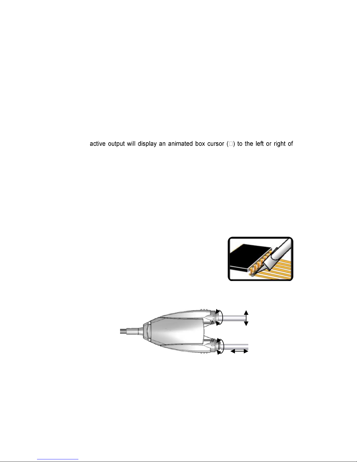
Multi-lead components can be drag soldered using Metcal hoof-tip cartridges. Tin
the working face of the tip with solder and gently drag it across the array of leads.
SMT REMOVAL
First, measure the dimensions of your component, then, use the SMTC charts
that are available from Metcal’s web page (www.metcal.com) to match
component and tip dimension.

9
8. BASIC TROUBLESHOOTING GUIDE
Problem: LCD displays ‘Open Source’.
1. Ensure cartridge is properly seated.
2.
3. Tighten hand-piece connector to output connector.
Problem: Solder hand-piece tip cartridge does not heat up.
1. Replace tip cartridge.
2. If problem persists, replace hand-piece with known good hand-piece and insert
new cartridge.
3. If cartridge heats up, replace non-functioning hand-piece.
Problem: Low power operation of the unit.
Check input power to the unit. The unit can draw up to 10A of current at 110V.
Do not plug into power sources such as power strips that are rated less than 10A.
Multiple high current devices plugged into the same electrical circuit can cause low
power operation, distribute high current devices among multiple circuits or increase
the electrical circuit capacity.
Problem: Non-Conforming Cartridge Detected
When the system detects any cartridge that exceeds its’ predefined allowable
power draw on the soldering unit, the following messages will appear on the
screen.
To correct the error, replace the tip cartridge. If the problem persists, contact Metcal
(support@metcal.com)

10
9. Safety
With power applied, the tip temperature can be > 300°C. Failure to observe the following
precautions may lead to injury to users or damage the equipment:
Do not touch any metallic parts of the hand-piece
Do not use near flammable items
Do not use unit for any function other than described in this manual
Use only genuine Metcal replacement parts
Use in a well ventilated area or with fume extraction
Do not use the equipment with wet hands
Connect only to properly grounded outlets to prevent risk of electric shock.
Always place hand-piece back into the work stand to prevent accidental
burning of oneself or surrounding objects.
This appliance is not intended for use by persons (including children) with
reduced physical, sensory or mental capabilities, or lack of experience and
knowledge, unless they have been given supervision or instruction concerning
use of the appliance by a person responsible for their safety.
Children should be supervised to ensure that they do not play with the
appliance.
Although the systems offer superior EOS (Electrical Overstress) protection, periodic
checks of the instrument cord should be incorporated into standard operator
maintenance procedures.
Waste Electrical and Electronic Equipment Directive - WEEE (2002/96/EC).
When this product is no longer required, if it cannot be re-used,
we ask our customers not to dispose of it as unsorted municipal
waste but to appropriately recycle the product. In Europe, please
contact your OK International distributor who can advise the
recycling options available (www.metcal.com).
WARNING
!

11
INHALTSVERZEICHNIS
1. SYSTEMSPEZIFIKATIONEN 11
2. AUFBAU UND TECHNOLOGIE DES SYSTEMS
a. SmartHeat®Technologie, keine Kalibrierung erforderlich 11
3. STROMVERSORGUNG
a. Merkmale 12
b. Betriebszustände 13
4. LÖTWERKZEUGE 13
5. LÖTPATRONEN
a. Metcal-Lötpatronen 14
b. Auswahl der passenden Spitzengeometrie 14
c. Auswahl der Serie mit der passenden Temperatur 15
d. Temperaturen (Serien) 15
6. BETRIEB
a. Ersteinrichtung 16
b. Austauschen aller Spitzenpatronen 16
c. MX-PTZ und TALON 16
d. Spitzenausrichtung beim MX-PTZ 16
e. Benutzerprogrammierbare PowerSave-Einstellung (Stromsparmodus)
17
f. BENUTZERSELEKTIERTES ENERGIEN-DIAGRAMM 17
7. ANWENDUNGSHINWEISE
a. Längere Spitzenstandzeit 17
b. Entzinnte Spitzen 17
8. GRUNDLEGENDE PROBLEMBEHEBUNG 18
9. SICHERHEIT 19
Garantie
OK International gewährt auf Geräte vom Typ MX-500 eine Garantie gegen Material-
und Konstruktionsfehler von vier (4) Jahren ab dem Datum des Kaufs durch den
Erstbesitzer. Diese Garantie schließt die normale Wartung aus und gilt nicht für
geöffnete, unsachgemäß oder zweckentfremdet verwendete, modifizierte oder
beschädigte Geräte. Wenn innerhalb des Garantiezeitraums Mängel am Produkt
auftreten, repariert oder ersetzt OK International es kostenlos nach eigenem Ermessen.
Das reparierte oder ersetzte Gerät wird frachtfrei an den ursprünglichen Käufer
geschickt. Der Garantiezeitraum beginnt ab Zeitpunkt des Kaufs. Wenn das Kaufdatum
nicht nachgewiesen werden kann, gilt das Herstellungsdatum als Beginn des
Garantiezeitraums.
Bitte besuchen Sie die Webseite von OK International (www.metcal.com) oder
wenden Sie sich an Ihren Metcal-Vertreter vor Ort. Dort finden Sie Informationen
über Systeme, Zubehör, technische Hinweise und vieles mehr.

12
1. SYSTEMSPEZIFIKATIONEN
Umgebungstemperatur bei Betrieb 10 - 40 °C
Maximale Gehäusetemperatur 55 °C
Netzspannung 100 - 240 V, geerdet
Netzfrequenz 50/60 Hz
Max. Leistungsabgabe. Max. 40 W je Kanal bei 22 °C Umgebungstemperatur
Ausgangsfrequenz 13,56 MHz
Netzkabel, 3-adrig 183 cm (18/3 Zoll) SJT
Abmessungen B x T x H 12,1 cm (4,8 Zoll) x 12,1 cm (4,8 Zoll) x 22.2,1 cm (8,8
Zoll)
Zertifizierung/Kennzeichnung cNRTLus, CE
Spannung Lötspitze zu Masse <2 mV
Widerstand Lötspitze zu Masse <2 Ohm
Leerlauftemperaturstabilität ± 1,1 °C bei ruhiger Luft
Länge des Lötgriffelkabels L = 183 cm (72 Zoll), brandsicher, ESD-
geschützt (gegen elektrostatische Entladung)
Lötgriffelanschluss F-Anschluss
2. KONSTRUKTION UND TECHNOLOGIE DES SYSTEMS
Bei der Serie MX-500 handelt es sich um ein Hochleistungs-Lötsystem mit höchster
Präzision und zwei umschaltbaren Anschlüssen. Es ist das neueste Modell der
marktführenden Metcal-Lötsysteme. MX-500 ist mit neuartigen ergonomischen
Lötgriffeln, einer neuen integrierten Leistungsanzeige, 40 Watt Leistung und
SmartHeat® Technologie für schnelles Ansprechen und präzises Arbeiten
ausgestattet.
a. SMARTHEAT®TECHNOLOGIE
Keine Kalibrierung erforderlich
Jede Patrone enthält ein selbstregulierendes Heizelement, das die eigene
Temperatur ‘erkennt’ und seine voreingestellte Leerlauftemperatur für optimale
Standzeit streng einhält. All dies wird von der exklusiven SmartHeat®Technologie
von OK International gesteuert. Die Spitzentemperatur wird durch inhärente
metallurgische Eigenschaften des Heizelements bestimmt. Einstellungen oder
Zubehör sind nicht erforderlich. Dies eliminiert Spitzen und Übergänge im
Zusammenhang mit elektrisch geschalteten Elementen in herkömmlichen
Lötkolben. Die integrierte Leistungsanzeige überwacht selbsttätig die je nach
thermischer Belastung an die Spitze abgegebene Leistung. Die Leistungsanzeige
erfordert keinerlei Kalibrierung, da die Messung in einer aktiven
Rückkopplungsschleife abläuft. Bitte wenden Sie sich mit allen Fragen an Ihren OK
International-Vertreter.
Für eine regelmäßige Überprüfung der Systemleistung gehen Sie bitte
folgendermaßen vor:
Messen Sie die Leistung des Systems als ‘erforderliche Zeitdauer zum Löten
einer festgelegten Werkstückanzahl’ oder
Kontrollieren Sie die Anfahr- und Leerlaufleistung mit der integrierten
Leistungsanzeige oder
Messen Sie die Leerlauftemperatur der Spitze (sie ist der Leistung proportional).

13
3. STROMVERSORGUNG
a. MERKMALE
LCD-Anzeige
Die MX-500-Serie ist mit einer integrierten LCD-Anzeige ausgestattet, die
Systeminformationen anzeigt, u.a.:
Integrierte Leistungsanzeige
Die Leistungsanzeige der Serie MX-500 bietet grafische und numerische
Leistungsinformationen.
Benutzerprogrammierbare PowerSave-Einstellung (Stromsparmodus)
Die MX-500-Serie verfügt über einen individuell einstellbaren Stromsparmodus.
Die Wartezeit für den Stromsparmodus kann zwischen 10 und 120 Minuten
eingestellt werden.
Universal-Stromversorgung
Die Geräte der Serie MX-500 erkennen automatisch die Eingangsspannung
und richten sich selbsttätig darauf ein. So ist ein Betrieb in allen Ländern ohne
spezielle Adapter oder Leistungseinbußen möglich.
LCD-Anzeige
Ausgangswahl-/
Befehlstaste
Netzschalter
Linker Ausgang
Rechter Ausgang
Integrierter Tragegriff
Stromanschluss
Vorderseite
Rückseite

14
b. BETRIEBSZUSTÄNDE
BEREIT
1. Lötgriffel nicht im Arbeitsständer.
2. System ist betriebsbereit.
STANDBY
1. Lötgriffel im Arbeitsständer.
2. Stromzufuhr zum Lötgriffel reduziert.
BETRIEB
1. Lötgriffel nicht im Arbeitsständer.
2. System wird verwendet. Leistungsanzeige zeigt Spannung an der Spitze an.
STROMSPARMODUS
1. Lötgriffel im Arbeitsständer.
2. Stromzufuhr zum Lötgriffel abgeschaltet.
3. LCD-Anzeige blinkt.
4. Mit Befehlstaste zurücksetzen.
4. LÖTGRIFFEL
Die MX-500-Serie bietet eine Auswahl unterschiedlicher Lötgriffel für die
verschiedensten Anwendungen. Für jeden Lötgriffel gibt es ein eigenes Sortiment an
Lötpatronen mit unterschiedlichsten Spitzengeometrien und Temperaturbereichen.

15
5. LÖTPATRONEN
a. Metcal-Lötpatronen
Die Löt- und Rework-Patronen umfassen Spitze, Heizelement, Spule, Anschluss
und Schaft. Die Patronen bieten bei richtiger Pflege der Spitze höchste Präzision
und Standzeit (siehe Abschnitt 8).
Die Auswahl der geeigneten Lötpatrone hängt von folgenden Faktoren ab:
Zugänglichkeit
Art der Lötung
Größe und Masse des Lötmittels
Bauteil
Eine sorgfältige Auswahl der Lötpatrone gewährleistet einen optimalen Lötvorgang.
Einige Überlegungen zur Auswahl einer geeigneten Löt- bzw. Rework-Patrone.
b. Auswahl der passenden Spitzengeometrie
Für Metcal-Lötpatronen gibt es eine breite Auswahl an Spitzengeometrien und
Temperaturbereichen. Eine aktuelle und vollständige Liste finden Sie auf unserer
Website (www.metcal.com). Es gibt Spitzengeometrien für die unterschiedlichsten
Anwendungen, von filigraner Präzisionsarbeit bis hin zu schweren Bodenplatten.
1. Wählen Sie eine Spitze mit größtmöglichem Kontaktbereich zwischen
Lötstelle und Spitze. Ein großer Kontaktbereich gewährleistet eine gute
Wämeübertragung und somit schnellere und bessere Lötergebnisse.
2. Wählen Sie eine Spitze, die einen guten Zugang zur Lötstelle ermöglicht.
Kürzere Spitzen erlauben schnelleres Arbeiten. Längere oder angewinkelte
Spitzen können bei dicht bestückten Leiterplatten erforderlich sein.
3. Wählen Sie die Lötpatrone mit dem niedrigsten Temperaturbereich, der für
die Lötung möglich ist. Damit senken Sie das Risiko von Hitzeschäden. Der
Temperaturbereich ist auf dem Schaft der Heizelementspitze angegeben
(Näheres auf Seite 8).
Zu groß
Lötauge für Löten/Rework
Lötauge zum Entlöten
Korrekt
Korrekt
Zu klein
Zu groß
Zu klein

16
c. Auswahl der Serie mit der passenden Temperatur
Jede Metcal-Lötpatrone ist speziell auf höchste Leistungsabgabe optimiert. Damit
können Sie häufig schon bei Temperaturen arbeiten, die um 40 °C oder mehr unter
der bei herkömmlichen Lötkolben erforderlichen Temperatur liegen. Da Metcal-
Lötpatronen die thermische Belastung erkennen und sich darauf einstellen, müssen
Sie die Größe des verwendeten Lötmittels nur ungefähr bestimmen. Beginnen Sie
zunächst bei niedriger Temperatur und steigern Sie diese erst bei Bedarf allmählich.
d. Temperaturen (Serien)
Anwendung
X= Serie
STTC
SMTC
UFTC
PTTC
TATC
STDC
Hohe thermische
Empfindlichkeit
Serie
500
5
5
5
Mittlere
thermische
Empfindlichkeit
Serie
600
0
0
6
6
0
Mittlere
thermische
Masse
Serie
700
1
1
F
7
1
Hohe thermische
Masse
Serie
800
8
8
8
8
Hinweis: Bei einigen Ausführungen sind nicht alle Temperaturen (Serien) erhältlich.
Eine vollständige Liste finden Sie im Katalog oder auf der Metcal-Webseite
(www.metcal.com).
Anschluss
Spuleneinheit
sembly
Spitze
Schaft
Heizelement
SMTC-X60
LOT 1212
Temperaturtabelle
(Serie)
Losnr.
Ausführung
Magnetische
Abschirmung
Serie
KONSTRUKTION UND BEZEICHNUNG DER PATRONE

17
6. BETRIEB
a. ERSTEINRICHTUNG
1. Schließen Sie die Lötgriffel an die Ausgangsanschlüsse des Stromgeräts an.
2. Führen Sie die ausgewählte Lötpatrone in den Lötgriffel ein.
3. Schieben Sie die Lötpatrone ganz ein.
Bei TATC-Patronen richten Sie die flache Seite des Lötpatronenschaftes an
der Öffnung im Griff aus. Schieben Sie die Lötpatrone ganz ein. Die
Lötpatrone ist ganz eingeschoben, wenn die Einschubmarkierung mit dem
Griff übereinstimmt. Nicht über diese Markierung hinaus einschieben.
Wiederholen Sie den Vorgang mit der zweiten Lötpatrone.
4. Stellen Sie den/die Lötgriffel in den/die entsprechenden Arbeitsständer.
5. Benetzen Sie den Schwamm des Arbeitsständers (falls vorhanden) mit
destilliertem Wasser (schwefelfrei).
6. Stecken Sie das Netzkabel in eine Schukosteckdose mit der angegebenen
Netzspannung ein.
7. Drücken Sie den Netzschalter, um das Gerät einzuschalten. HINWEIS: Das
Gerät muss geerdet sein, andernfalls lässt es sich nicht einschalten. Das
Gerät funktioniert nicht an einem Stromnetz mit Trenntrafo.
8. Wählen Sie an der Ausgangswahl-/Befehlstaste den gewünschten Ausgang.
Links bzw. rechts auf der Anzeige zeigt der aktive Ausgang einen blinkenden
Cursor in einem Kästchen ( an.
b. AUSTAUSCHEN ALLER SPITZENPATRONEN
1. Schalten Sie das Gerät aus.
2. Ziehen Sie die Lötpatrone mithilfe der Unterlage zur Lötpatronenentfernung
(MX-CP1) heraus. HINWEIS: DIE SPITZE DER LÖTPATRONE KANN SEHR
HEISS SEIN. LÖTPATRONEN NICHT MIT METALLWERKZEUGEN (ZANGE
O. Ä.) ENTFERNEN!
3. Schieben Sie eine neue Lötpatrone in den Griff ein.
4. Stellen Sie den/die Lötgriffel in den/die entsprechenden Arbeitsständer.
5. Schalten Sie den Netzschalter auf “ON” (Ein). Die neue Lötpatrone heizt sich
sehr schnell auf Betriebstemperatur auf.
c. MX-PTZ UND TALON
1. Säubern und verzinnen Sie die Spitzen nach dem
Aufheizen.
2. Die Spitze muss alle Leiterstifte des Geräts
berühren, dabei lässt sich der konische oder auch
der gerade Bereich der Spitze verwenden.
Erzeugen Sie mithilfe des Lötmittels eine
thermische Brücke zwischen den Leiterstiften.
3. Drücken Sie das Lötwerkzeug. Warten Sie, bis alle
Leiterstifte aufgeschmolzen sind.
4. Halten Sie den Druck aufrecht, anschließend heben Sie das Bauteil ab.
d. SPITZENAUSRICHTUNG BEIM MX-PTZ
Thermische Brücke

18
e. BENUTZERPROGRAMMIERBARE POWERSAVE-EINSTELLUNG
(STROMSPARMODUS)
1. Halten Sie im Bereitschaftsmodus die Ausgangswahl-/Befehlstaste 3
Sekunden lang gedrückt, bis sie zu blinken beginnt.
2. Nun lassen Sie die Ausgangswahl-/Befehlstaste wieder los.
3. Drücken Sie nun die Ausgangswahl-/Befehlstaste so oft, bis die gewünschte
Zeitdauer eingestellt ist. Mit jedem Tastendruck erhöht sich die Zeit um 10
Minuten.
4. Zum Schluss halten Sie die Ausgangswahl-/Befehlstaste erneut 3 Sekunden
lang gedrückt, um in den Betriebsmodus zurückzukehren.
f. BENUTZERSELEKTIERTES ENERGIEN-DIAGRAMM
1. Halten Sie im Bereitschaftsmodus die Ausgangswahl-/Befehlstaste 3
Sekunden lang gedrückt, bis sie zu blinken beginnt.
2. Nun lassen Sie die Ausgangswahl-/Befehlstaste wieder los.
3. Betätigen Sie und halten Sie den Ausgangs-Wähl-/Befehlsknopf für 3
Sekunden
4. Nun lassen Sie die Ausgangswahl-/Befehlstaste wieder los.
5. Betätigen Sie sich, Vorwahl/Befehls-Knopf auszugeben, bis das gewünschte
Balkendiagramm angezeigt ist; Standard- oder UltraFine.
6. Zum Schluss halten Sie die Ausgangswahl-/Befehlstaste erneut 3 Sekunden
lang gedrückt, um in den Betriebsmodus zurückzukehren.
7. ANWENDUNGSHINWEISE:
a. LÄNGERE SPITZENSTANDZEIT
1. Entfernen Sie täglich Schaft und Griff der Lötpatrone und kontrollieren und
reinigen Sie diese mit denaturiertem Alkohol und einem sauberen Tuch.
Hartnäckige Flussmittelrückstände auf dem Schaft (und der ganzen SMTC-,
PTTC- und TATC-Spitze) können Sie mit einer Messingborstenbürste
entfernen.
2. Behandeln Sie nach dem Anschalten des Systems und nach jedem
Wiedereinsetzen der Spitze in den Halter die verzinnten Flächen der Spitze
mit Lötmittel. Das Lötmittel schützt die Spitze vor Oxidation und verlängert ihre
Standzeit.
3. Wählen Sie die Lötpatrone mit dem niedrigsten Temperaturbereich, der für die
Lötung möglich ist. Niedrigere Temperaturen verringern Oxidation an der
Spitze und sind weniger belastend für die zu verbindenden Bauteile.
4. Verwenden Sie Lötspitzen mit Präzisionsspitze nur, wenn es erforderlich ist.
Die Beschichtung von Präzisionsspitzen ist weniger haltbar als die größerer
Spitzen.
5. Verwenden Sie Lötspitzen niemals als Hebelwerkzeug. Ein Biegen der Spitze
kann Risse in der Beschichtung hervorrufen und die Spitzenstandzeit
verkürzen.
6. Verwenden Sie so wenig Aktivierungsflussmittel wie für das jeweilige Lötmittel
möglich. Größere Mengen Aktivierungsflussmittel wirken stärker korrodierend
auf die Spitzenbeschichtung.
7. Bringen Sie das Lötmittel nur auf die zu verbindenden Bauteile auf, nicht auf
die heiße Lötspitze.
8. Schalten Sie das System bei Nichtverwendung aus.
9. Üben Sie keinen Druck auf die Spitze aus. Mehr Druck bedeutet nicht mehr
Hitze. Wenn Sie die Wärmeübertragung verbessern möchten, bilden Sie eine
thermische Brücke aus Lötmittel zwischen Spitze und Lötstelle.
10. Säubern Sie die Spitze auf einem sauberen feuchten Schwamm oder mit einer
Messingbürste -- nicht mit einem Lappen oder schmutzigen und trockenen
Schwamm.
b.ENTZINNTE SPITZEN
Wenn eine Spitze kein Lötmittel annimmt, so ist sie entzinnt. In diesem Fall
kann die Beschichtung oxidieren, was die Wärmeübertragung der Spitze
erheblich beeinträchtigt. Entzinnen wird verursacht durch:
Other manuals for MX500
3
Table of contents
Languages:
Other Metcal Soldering Gun manuals

Metcal
Metcal RSS-1000-CVSI-NC User manual

Metcal
Metcal HCT-900 User manual

Metcal
Metcal Metcal MX-5200 User manual

Metcal
Metcal GT90 User manual

Metcal
Metcal MX-5000 Series User manual

Metcal
Metcal BVX-200 User manual

Metcal
Metcal MX-500P User manual

Metcal
Metcal RSS-1000-CVSI User manual

Metcal
Metcal PS-900 User manual

Metcal
Metcal MX500 User manual