Rain Bird 11000 Series Manual

Rain Bird 11000 Series Rotors
Operations & Maintenance Manual
Rotores Rain Bird da série 11000
Manual de funcionamento e manutenção

2
Rain Bird 11000 Series Rotor Operation and Maintenance Manual
THANK YOU FOR CHOOSING
RAIN BIRD.
We are aware that you have a choice, and we are
happy you chose Rain Bird.
Rain Bird Rotors oer a wide range of features plus
easy maintenance.
This manual shows how to perform common
installation and maintenance procedures. If you
have any comments or questions please call your
local Rain Bird distributor.
TABLE OF CONTENTS
Important Installation & MaintenanceTips ......3
Arc Adjustment ...............................4
11000 Full/Part-Circle Adjustment ..............5
Removing the Internal Assembly ...............7
Installing the Internal Assembly ................8
Rain Bird 11000 Series Rotor Operation and Maintenance Manual
Manual de funcionamento e manutenção de rotores da série 11000 da Rain Bird
OBRIGADO POR ESCOLHER A
RAIN BIRD.
Estamos cientes de você tem uma escolha, e
estamos contentes de que você escolheu a Rain
Bird.
Os rotores da Rain Bird oferecem uma ampla
gama de recursos, além de fácil manutenção.
Este manual mostra como realizar
procedimentos comuns de instalação e de
manutenção. Se você tiver comentários ou
perguntas, ligue para o seu distribuidor local da
Rain Bird.
SUMÁRIO
Dicas importantes de instalação e de
manutenção .............................3
Ajuste do arco............................4
11000 Ajuste do círculo completo/parcial ....5
Extração do mecanismo interno.............7
Instalação do mecanismo interno ...........8

3
Rain Bird 11000 Series Rotor Operation and Maintenance Manual
IMPORTANT INSTALLATION &
MAINTENANCETIPS
• To avoid debris problems, ush the system
before installing the ROTOR on the swing joints.
If debris gets in the line, ush the line.
• For ACME thread rotors, you must use an ACME
thread swing joint assembly. DO NOT use
plumbers tape or pipe dope. Do not tighten
completely against swing joint tting. (Turn the
rotor back counter-clockwise one-quarter (¼) of a
turn from tightened position.)
• Rain Bird does not recommend using metal
ttings with Rain Bird Rotors. If metal ttings
must be used, hand tighten only.
• Rain Bird Rotors may be installed at ground level
in all soil types.
• For part-circle applications, locate the
xed left edge by rotating the nozzle turret
counterclockwise.
Rain Bird 11000 Series Rotor Operation and Maintenance Manual
Manual de funcionamento e manutenção de rotores da série 11000 da Rain Bird
DICAS IMPORTANTES DE
INSTALAÇÃO E DE MANUTENÇÃO
• Para evitar problemas de impurezas, limpe o
sistema antes de instalar o ROTOR nas juntas
articuladas. Se impurezas entrarem na linha,
limpe-a.
• Para rotores com rosca ACME, você deve
usar um conjunto de junta articulada com
rosca ACME. NÃO utilize ta de encanador
ou ta adesiva para canos. Não aperte
completamente no encaixe da junta
articulada. (Gire o rotor um quarto (¼) no
sentido anti-horário da posição apertada.)
• A Rain Bird não recomenda usar encaixes de
metal com os rotores da Rain Bird. Se encaixes
de metal devem ser usados, somente aperte-
os à mão.
• Os rotores da Rain Bird podem ser instalados a
nível do solo em todos os tipos de solo.
• Para aplicações de círculo parcial, localize
o canto esquerdo xo movendo o torrão do
bocal em sentido anti-horário.

4
Rain Bird 11000 Series Rotor Operation and Maintenance Manual
ARC ADJUSTMENT
Required Tool: Flat-head screwdriver
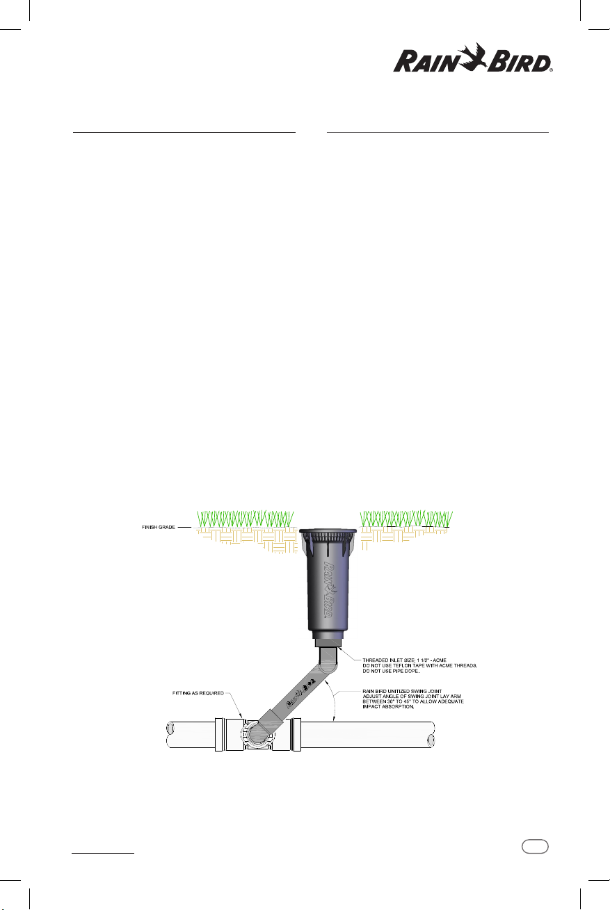
The LEFT leg of the sprinkler’s arc is
the xed leg.The 11000 Series Rotor
is shipped in full circle mode. Align
the left leg where it is needed for
your desired watering pattern while
installing the rotor case on the
swing joint.
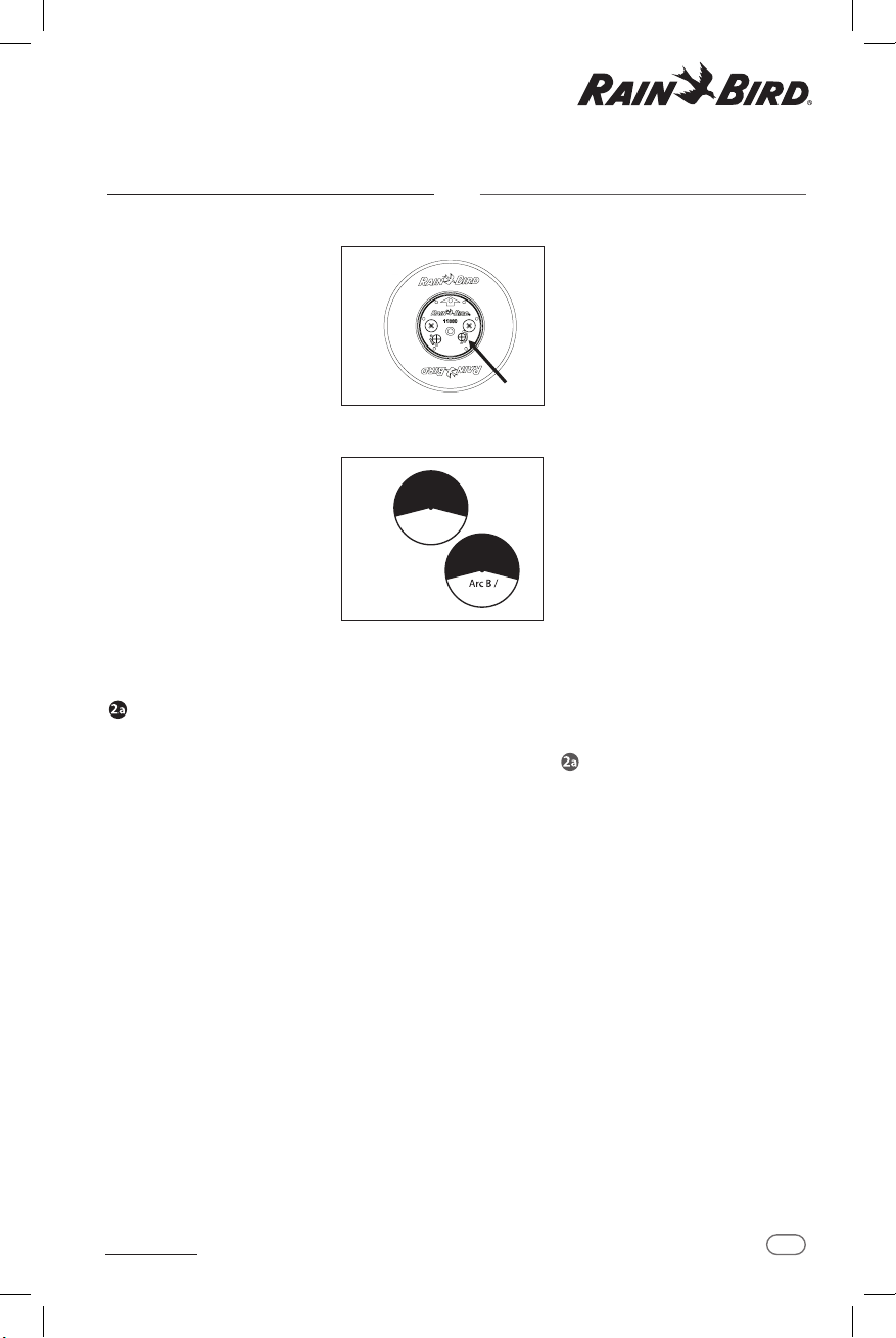
The RIGHT leg of the arc is the
adjustable leg. It is shipped from the
factory at approximately 180 degrees
from the xed leg.
For best results, turn the head ON
to see where both legs“trip”(the
trip point is the point where the
rotor turns and begins rotating in
the opposite direction).To manually
advance the nozzle housing, SLOWLY
move it in the same direction it is
currently moving. After noting where
the head trips, return the head to
the left trip point. CAUTION: Do not
turn the turret manually against
the direction of rotation while in
operation.
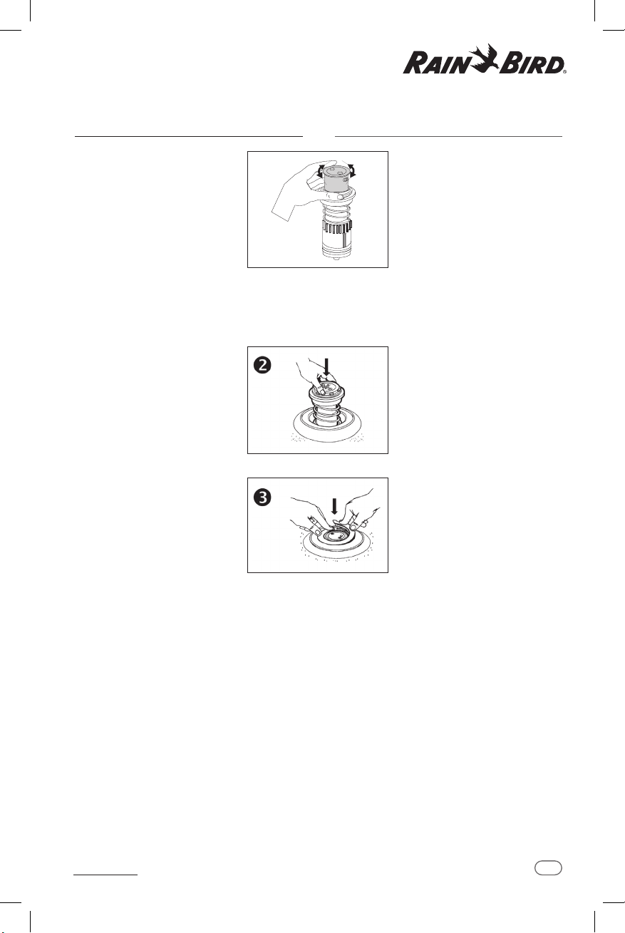
Using a at-head screwdriver, turn
the arc adjustment screw on top of
the nozzle housing to reach your
desired arc.
Turn the screw clockwise to add arc,
or counterclockwise to subtract arc.
One complete turn of the adjustment
screw equals approximately 58
degrees of arc. 11000 Series rotors
are adjustable from 30° to 345°.
CAUTION: Turning the arc adjustment
past the stop may damage the
internal.
Turn on the rotor and let it run through
the forward and backward trip points to
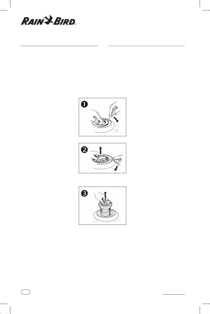
verify the arc setting. Repeat steps 1 through 4 as needed.You
may also pull the internal assembly out of the rotor and adjust
the arc.Then reinstall the internal assembly and check for
performance.
Rain Bird 11000 Series Rotor Operation and Maintenance Manual
Manual de funcionamento e manutenção de rotores da série 11000 da Rain Bird
AJUSTE DO ARCO
Ferramenta necessária: Chave de fenda de cabeça chata
A perna ESQUERDA do arco do
aspersor é a perna xa. O rotor da
série 11000 é entregue em modo
de círculo completo. Alinhe a perna
esquerda onde for necessário para
o padrão de irrigação ao instalar o
estojo do rotor na junta articulada.
A perna DIREITA do arco é a perna
ajustável. É despachada da fábrica
a aproximadamente 180 graus da
perna xa.
Para melhores resultados, LIGUE o
rotor para localizar ambas as tampas
(a tampa é o ponto em que o rotor
gira e começa a rodar na direção
oposta). Para avançar manualmente
o alojamento do bocal, mova-a
LENTAMENTE na mesma direção
em que está se movendo agora.
Depois de localizar onde a direção
do cabeçote muda, coloque-o
novamente no batente esquerdo.
ATENÇÃO: Não gire o torreão
manualmente na direção da
rotação quando em operação.
Usando uma chave de fenda de
cabeça plana, gire o parafuso de
ajuste do arco na parte superior do
alojamento do bocal, até alcançar o
arco desejado.
Gire o parafuso no sentido horário
para abrir mais o arco, ou anti-
horário para diminuir a abertura
do arco. Um giro completo do
parafuso de ajuste equivale a
aproximadamente 58 graus do
arco. Os rotores da série 11000 são
ajustáveis de 30° a 345°.
ATENÇÃO: Girar o arco de ajuste além
do limite pode danicar o mecanismo
interno.
Ligue o rotor e deixe-o correr entre
ambos os limites para vericar o ajuste
do arco. Repita os passos 1 a 4 conforme
a necessidade.Você também pode tirar
o mecanismo interno do rotor e ajustar o
arco. Então reinstale o mecanismo interno
e verique o funcionamento.

5
Rain Bird 11000 Series Rotor Operation and Maintenance Manual
11000 FULL/PARTCIRCLE
ADJUSTMENT
Required Tool: Flat-head screwdriver
The FULL/PART-CIRCLE choice is made
by turning the white adjustment
arrow in the appropriate direction
until it stops.Towards the HALF
CIRCLE for Part-Circle operation.
Towards the SOLID CIRCLE for Full
Circle operation. When the white
screw is returned to the PART CIRCLE
position, the previously set edge
adjustments are used.
IMPORTANT NOTE: Apply downward
pressure on screw driver to ensure it fully
engages into the slot.
The 11000 Series rotor can operate in
one of two Part Circle arc settings.The
primary arc (Arc A) and a secondary
arc (Arc B)
Note:When internal is removed from
the case, to ensure the rotor is in the
Primary arc, put internal in Full Circle
align arrows on riser assembly and
nozzle base, then put the unit back
into Part Circle mode. Install the
internal in case.
To change irrigation from Arc A to Arc
B:Turn the Rotor rotation adjustment
screw from its PART CIRCLE to FULL
CIRCLE setting. Allow the Rotor to
turn until the spray direction is in the
Arc B range. Turn the Rotor rotation
adjustment screw from FULL CIRCLE
to PART CIRCLE. Reverse these steps
to change back from Arc B to Arc A.
Arc A /
Sector A
Arc A /
Arco A
Arco B
Rain Bird 11000 Series Rotor Operation and Maintenance Manual
Manual de funcionamento e manutenção de rotores da série 11000 da Rain Bird
AJUSTE DO CÍRCULO COMPLETO/
PARCIAL 11000
Ferramenta necessária: Chave de fenda de cabeça chata
Pode-se escolher entre o CÍRCULO
COMPLETO/PARCIAL girando a seta de
ajuste branca na direção apropriada
até que ela pare. No CÍRCULO PARCIAL
para operar em Círculo Parcial. No
CÍRCULO SÓLIDO para operar em
Círculo Completo. Quando o parafuso
branco gira de volta à posição de
CÍRCULO PARCIAL, o ajuste de arco
anterior será utilizado.
OBSERVAÇÃO IMPORTANTE: Aplique
pressão para baixo na chave de fenda para
garantir que se encaixe completamente na
fenda.
O rotor da série 11000 pode funcionar
em um dos dois ajustes do arco do
Círculo Parcial. O arco primário (Arco A)
e um arco secundário (Arco B)
Observação: Se o mecanismo interno
é retirado do estojo, para garantir que
rotor esteja no arco primário, coloque
o mecanismo interno em Círculo
Completo, alinhe as echas do tubo
de subida e da base do bocal, e volte a
colocar a unidade em modo de Círculo
Parcial. Instale a parte interna no
estojo.
Para mudar a irrigação do Arco A para
o Arco B: Gire o parafuso de ajuste de
rotação do Rotor do CÍRCULO PARCIAL
ao CÍRCULO COMPLETO. Permita que
o Rotor gire até que a direção da
pulverização esteja no alcance do Arco
B. Gire o parafuso de ajuste de rotação
do rotor de CÍRCULO COMPLETO a
CÍRCULO PARCIAL. Inverta essas etapas
para mudar do Arco B para o Arco A.

6
Rain Bird 11000 Series Rotor Operation and Maintenance Manual
REMOVING THE INTERNAL
ASSEMBLY
IMPORTANT NOTE: Make sure the sprinkler does not
operate automatically while you are removing the
internal assembly. Turn o the water.
Clean around the top of the case to prevent debris from
falling in when the internal is removed.
Required Tool: Flat-head screwdriver
While pressing down on the center
of the nozzle housing, insert a
screwdriver into the slot on the snap
ring and pry up the snap ring from
the top of the rotor case.
NOTE: You MUST press down on the
nozzle housing when removing the
snap ring.
Insert a at-head screwdriver into the
groove (or under the small tabs) on
the outside edge of the bearing guide
and use the screwdriver to gently pry
up the internal assembly.
Lift the internal assembly up and out
of the case.
Rain Bird 11000 Series Rotor Operation and Maintenance Manual
Manual de funcionamento e manutenção de rotores da série 11000 da Rain Bird
EXTRAÇÃO DO MECANISMO
INTERNO
OBSERVAÇÃO IMPORTANTE: Certique-se de que o
aspersor não esteja em modo automático quando
você estiver extraindo o mecanismo interno.
Desligue a água.
Limpe a parte superior do estojo para evitar a
entrada de impurezas quando o mecanismo interno
for extraído.
Ferramenta necessária: Chave de fenda de cabeça
chata
Enquanto pressiona com a mão
a parte central do alojamento do
bocal, insira uma chave de fenda
na fenda do anel de retenção e
levante-o da parte superior do
estojo do rotor.
OBSERVAÇÃO: Você DEVE
pressionar o alojamento do bocal
para remover o anel de retenção.
Insira uma chave de fenda na fenda
(ou sob as pequenas abas) na
borda externa da guia e use a chave
de fenda para extrair o mecanismo
interno com cuidado.
Levante o mecanismo interno e
retire-o do estojo.

7
Rain Bird 11000 Series Rotor Operation and Maintenance Manual
INSTALLING THE INTERNAL
ASSEMBLY
PART-CIRCLE ROTORS:To nd the
left-stop, turn the nozzle housing
to the right until it reaches its“trip”
point.Then turn the nozzle housing
back to the left until it“trips”again.
The location of the arrow on top of the
nozzle housing indicates the direction
of the nozzle.
Align the arrow on the nozzle housing
with the left edge of the grass line
(left edge of your watering pattern).
Then make your right arc adjustment.
Lower the internal assembly back into
the case and press down rmly until
the internal assembly seats securely
and evenly in the case.
Clean and position the snap ring in
the groove on the top of the rotor
case with the bottom of the snap ring
facing down.
Press the end of the snap ring without
the screwdriver slot into the groove.
Press and twist the snap ring down
in a circular motion until it is installed
about two-thirds of the way.
Step on or pound the snap ring (with a screwdriver handle
or a similar tool) to insert it the rest of the way. Make sure
the snap ring fastens securely in place and is ush with the
top of the rotor case.
FULL-CIRCLE MODELS: Installing the full-circle internal
assembly is the same as the part-circle, except that you do not
need to adjust the arc.
Rain Bird 11000 Series Rotor Operation and Maintenance Manual
Manual de funcionamento e manutenção de rotores da série 11000 da Rain Bird
INSTALAÇÃO DO MECANISMO
INTERNO
ROTORES DE CÍRCULO PARCIAL: Para
encontrar o limite esquerdo, gire o
alojamento do bocal para a direita
até encontrar resistência. Então
gire o alojamento do bocal de
volta para esquerda até encontrar
resistência de novo. A posição de
echa situada na parte superior
do alojamento do bocal indica a
direção do bocal.
Alinhe a echa do alojamento do
bocal com a borda esquerda da
linha da grama (borda esquerda
do seu padrão de irrigação). Então
faça o ajuste do seu arco direito.
Volte a inserir o mecanismo
interno no estojo e pressione-o
rmemente até ele estar seguro e
nivelado dentro do estojo.
Limpe e posicione o anel de
retenção na fenda situada na parte
superior do estojo do rotor, com a
parte inferior do anel de retenção
virado para baixo.
Pressione o extremo do anel de
retenção dentro da fenda sem a
chave de fenda. Aperte e torça o
anel de retenção até o inserir por
dois terços.
Pise ou bata no anel de retenção
(com o mango da chave de fenda ou ferramenta
semelhante) para inseri-lo completamente.
Certique-se de que o anel de retenção esteja xo no
lugar e nivelado com a parte superior do estojo do
rotor.
MODELOS DE CÍRCULO COMPLETO: A instalação do
mecanismo interno é igual ao do círculo parcial, exceto que
não é necessário ajustar o arco.

8
Rain Bird 11000 Series Rotor Operation and Maintenance Manual
REPLACING THE NOZZLE
IMPORTANT NOTE: Make sure the sprinkler does not
operate automatically while you are changing the
nozzle. Turn o the water.
NOTE: Make sure the snap ring is securely in place before
removing the nozzle housing screws.
Clean top of case assembly to prevent debris from falling
in when nozzle housing is removed.
Required Tools: Phillips-head screwdriver; Flat-head
screwdriver.
Use a Phillips-head screwdriver to
loosen the nozzle housing screws.
Grasp the nozzle housing screws and
lift up to separate the nozzle housing
from the internal.
Press the replacement nozzle
assembly into the nozzle housing,
making sure the nozzle front is ush
with the outside of the housing.
An O-ring seal is required on all
nozzles.
CAUTION: If the nozzle is not ush and
seated properly in the nozzle housing, the
rotor may not perform properly.
Rain Bird 11000 Series Rotor Operation and Maintenance Manual
Manual de funcionamento e manutenção de rotores da série 11000 da Rain Bird
SUBSTITUIÇÃO DO BOCAL
OBSERVAÇÃO IMPORTANTE: Certique-se de que o
aspersor não esteja em modo automático quando
você estiver mudando o bocal. Desligue a água.
OBSERVAÇÃO: Certique-se de que o anel de
retenção esteja rme antes de remover os parafusos
do alojamento do bocal.
Limpe a parte superior do estojo para evitar a
entrada de impurezas quando retirar o alojamento
do bocal.
Ferramentas necessárias: Chave de fenda Phillips;
Chave de fenda de cabeça chata.
Utilize uma chave de fenda
Phillips para soltar os parafusos do
alojamento do bocal.
Segure os parafusos do alojamento
do bocal e levante o alojamento do
bocal do mecanismo interno.
Coloque o bocal de reposição no
alojamento do bocal, certicando-
se de que sua parte frontal esteja
novelada com a superfície externa
do alojamento.
Todos os bocais exigem um anel de
vedação O’Ring.
ATENÇÃO: Se o bocal não estiver
nivelado e colocado corretamente no
alojamento do bocal, é possível que o
rotor não funcione corretamente.

At Rain Bird, we believe it is our responsibility
to develop products and technologies that
use water eciently. Our commitment also
extends to education, training and services for
our industry and our communities.
The need to conserve water has never
been greater. We want to do even
more, and with your help, we can. Visit
www.rainbird.com for more information
about The Intelligent Use of Water.™
The Intelligent Use of Water.
™
LEADERSHIP • EDUCATION • PARTNERSHIPS • PRODUCTS
®Registered Trademark of Rain Bird Corporation © 2023 Rain Bird Corporation 6/23
Rain Bird Corporation
6991 E. Southpoint Road
Tucson, AZ 85756
Phone: (520) 741-6100
Fax: (520) 741-6522
Rain Bird Technical Services
(800) RAINBIRD (1-800-724-6247)
(U.S. and Canada)
Rain Bird Corporation
970 West Sierra Madre Avenue
Azusa, CA 91702
Phone: (626) 812-3400
Fax: (626) 812-3411
Specification Hotline
800-458-3005 (U.S. and Canada)
Rain Bird International, Inc.
1000 West Sierra Madre Ave.
Azusa, CA 91702
Phone: (626) 963-9311
Fax: (626) 852-7343
The Intelligent Use of Water™
www.rainbird.com
D42213
Other manuals for 11000 Series
6
Table of contents
Other Rain Bird Lawn And Garden Equipment manuals

Rain Bird
Rain Bird 11000 Series Manual

Rain Bird
Rain Bird RBACS400 User manual

Rain Bird
Rain Bird Root Watering System User manual

Rain Bird
Rain Bird 1ZEHTMR User manual

Rain Bird
Rain Bird 3500 Series User manual

Rain Bird
Rain Bird R-VAN1318 User manual

Rain Bird
Rain Bird ST8-WiFi User manual

Rain Bird
Rain Bird 3500 Series User manual

Rain Bird
Rain Bird GRDNERKIT User manual

Rain Bird
Rain Bird R-VAN User manual