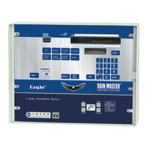
RainMaster RME HAWK User manual


THIS PAGE INTENTIONALLY LEFT BLANK.

Congratulations . . . you have chosen one of the most advanced irrigation
controllers available. Rain Master has taken great pride and patience in
developing and building the most trouble-free controllers in the irrigation
industry. Your RME HAWK has many high-end features. Features such
as accurate, economical flow sensing, and cycle and soak programming are
yours at the press of a button. In addition, your new RME HAWK controller
maintains full support of independent pump and normally closed or
normally open master valves. All this was designed to protect one of our
most precious resources…water… as well as your bottom line!
To take full advantage of the many features available in your RME HAWK
controller, please take a few minutes and read through your User Manual.
For those who do not have the time, a Quick Reference sheet is provided.
This sheet will allow you to perform many of the basic functions required
in programming and operating your controller.
1
RME HAWK

CONTROLLER BASIC FEATURES
• No batteries to replace, ever.
• Easy to identify and use keypad for ease of programming and review.
•Multiple displays provide a truly simple way of programming and information recall.
•The Review feature brings all the information for a given program(s) to the displays
with simple push of the Review Button.
• Non-volatile memory holds the program(s) indefinitely during power outages or
seasonal shut down.
• A "real time" clock holds the actual time during power outages without batteries.
This eliminates the need to reset the clock every time the power goes out.
•Four (4) completely independent programs with five (5) start times, for a total of 20
possible start times per day.
• Watering time(s) for each station can be set from 1 minute to 9 hrs 59 mins in 1
minute increments.
• Quick Stations allow for rapid programming of a block of stations with the same
watering time.
• Water Days for each program may be based on seven day week or a skip-by-day
routine allowing a program to skip from 1 to 30 days between watering.
•Programmable rain shut down allows you to select the number of days the controller will
stay off (in rain shut down mode) before it goes back into the automatic mode.
•Manually activated system check/syringe cycle allows you to sequentially run stations
for a user selectable time from 1 minute to 9 minutes.
• Manually activated program cycle allows you to run a program independent of its
programmed start time and water days.
•Manually activated station cycle allows you to run a single station for a selected time.
• Built-in remote control capability for Rain Master Remotes.
•Automatic field wire fault detection enables the controller to sense a short in the field
wire and instantly turn off that station, report the fault and move to the next
programmed station. No fuses or reset button to be concerned with.
• Rain Switch (auto-off) turns off all stations without disturbing the program(s).
• Available for 120 VAC, 50/60 HZ or 220/240 VAC 50/60 HZ power.
•Heavy duty 18-gauge jet coat, powder coated steel enclosure for outdoor or indoor use.
• Two convenient sized enclosures for easy installation of field wires.
• Extra heavy duty lightning and surge protected models available for areas where
lightning is a concern.
• Outdoor pedestal mount available for all models.
• C-UL and FCC approved.
•Percentage key allows you to increase or decrease all station runtimes on a percentage
basis in 1% increments from 0% to 300% by program.
• Built-in self test allows you to test the entire controller and field wires for faults,
thereby ensuring that the entire system is functioning correctly.
• Comes with a limited 5 year warranty.
2

CONTROLLER ADVANCED FEATURES
• Ability to select cycle-and soak programming or conventional programming on a per-
program basis.This feature includes:
-Ability to set RUNTIME, MAX CYCLETIME and SOAK time on a per station
basis.
-Automatic minimization of the water window by intelligently scheduling station
starts if and when other stations are satisfying their SOAK TIMES.
- QUICK STATIONS support for Cycle and Soak.
-ForTotal Runtime of a program in REVIEW, cycle and soak programs intelligently
displayTotal Runtime considering all soak delays, optimized program, water
budget percentage and interstation delay.
• Flow rate monitoring including:
- Main Line Break flow detection.
- Unscheduled flow detection.
- Station upper-limit flow detection.
- Programmable flow check delay (1-6 minutes).
- Monitor and display measured station flow in GPM.
-Automatic flow LEARN mode for setting individual station limits or manual entry
or semiautomatic monitor/set mode.
-Global percentage adjust to automatically factor upper flow limits for all stations.
- Automatic station advancement for station overflow.
- Audible and visual alert for all flow violations.
- Intelligent upper-limit processing for concurrent station operation.
- Automatic closure of normally open Master Valve on Main Line Break or
Unscheduled Overflow.
•Totalizer feature for tracking water usage in gallons to pinpoint specific water savings
and conservation efforts.
• Ability to select usage of the MasterValve per program.
• Ability to select a Normally Open or Normally Closed Master Valve.
• Ability to select usage of a Pump on a per program basis.
• Programmable Security Access code.
• Usage of a rain sensor on a per program basis.
• Programmable interstation delay from 0 to 255seconds in 1-second increments.
3

4
USER PROGRAMMABLE FEATURES (SETUP)
The following features can be easily selected or reconfigured by a single push of a button
(SETUP key)
• Programmable Master Valve allows you to program a Master Valve to go on
by program.
• Programmable type of Master Valve allows you to select either a Normally
Closed Master Valve or a Normally Open Master Valve.
• Programmable Pump allows you to program a Pump (independent of the
Master Valve) to go on by program.
•Programmable stacking or no stacking of programs allows you to have programs
run one after the other (Stack Mode) or at the same time (No Stack Mode).
• Programmable timer delay between stations allows you to program a time
delay from 0 to 255 seconds (4 minutes 15 seconds) to allow slow-closing
valves to completely shut off.
• Programmable security code allows you to enter a 1 - 4 digit number as a
security code which will prevent entry by unauthorized personnel.
•Programmable sensor allows you to have a sensor device enabled or disabled
for each program.
•Programmable alarm allows you to either enable or disable an audible alarm
in the event of a flow limit violation or a field wire fault detection.
•Programmable cycle and soak allows you to select each program to be either
a cycle and soak program or not.
• Programmable flow allows you to enable or disable the flow sensor features.
•Programmable pipe size allows you to select the pipe size for the flow sensor.
•Programmable main line flow limit allows you to set an upper flow limit from
1 to 999 GPM.This limit defines the maximum allowable controller flow
for scheduled irrigation.

•Programmable unscheduled flow limit allows you to setup an upper flow limit
from 0 to 999 GPM.This limit defines the maximum allowable flow when
there is no scheduled irrigation, e.g.. usage of manual quick coupler devices.
•Programmable flow check delay allows you to set up a delay after any station
changes, from 1 minute to 6 minutes, during which time no flow limits are
checked.
• Total Gallons allows you to view the total accumulated gallons and to clear
the total accumulated gallons.
•Programmable flow percentage allows you to set up a global percentage from
5% to 80% which will be used as an adjustment on all station upper flow
limits.
• Programmable station upper flow limits allows you to individually set an
upper flow limit from 0 GPM to 500 GPM for each station or to run a
watering profile during which the upper flow limit for each station will be
automatically set based on the measured flow and the global programmable
flow percentage.
5

THIS PAGE INTENTIONALLY LEFT BLANK.
6

7
MOUNTING AND INSTALLATION
CONTROLLER PLACEMENT
WARNING: Do not drill holes in the controller's case. It has all the holes necessary
for mounting it on a wall or pedestal. Drilling holes in the unit will cause metal
chips to mix with the electronics and this will cause the unit to malfunction. If, for
some reason, it is absolutely necessary to drill additional holes in the unit, carefully
remove all the electronics prior to doing so.
Controllers are suitable for indoor/outdoor environment. It is lockable, dust-free and rain
resistant. Outdoors the controller should be placed in a shaded and dry environment not
subject to direct sprinkler spray or continuous heavy moisture. Additionally, a pedestal
(PED 1) is available for outdoor controllers; contact your Rain Master distributor.
MOUNTING THE CONTROLLER
1. On an upright, flat and secure surface, place the mounting bracket at eye level and
fasten securely.
2. Mate the bracket on the back of the controller to the mounted bracket and hang the
controller.
3. Secure the bottom of the controller by placing a screw through the hole located in its
back wall at bottom center.
CONTROLLER CONNECTIONS – AC POWER
1. Refer to Figure 1 - Power and Field Wiring.
2. Mount controller.
3. Place Rain Switch in “No Watering” position.
4. Remove lower panel.
5. Using #10-gauge or heavier copper wire, connect ground screw to ground rod or
grounded water pipe using a ground rod clamp. The wire should be as short as possible
with no sharp bends or kinks. If multiple clocks are being installed in the same
location, use a ground rod for each and contact the factory for the RMIS pamphlet
on proper grounding techniques.
6. Thread condulet onto transformer.
7. Connect supply line grounded conduit to condulet.
8. Connect 120 V 50/60Hz supply line to transformer wires within the condulet
Install gasket and cover onto condulet with 2 screws.
9. Follow all appropriate electrical wiring codes.
10. Replace the lower panel and place the Rain Switch in “Automatic Watering” position
after field valve wiring is complete.
MOUNTING &
INSTALLATION

8
ELECTRICAL GROUNDING FOR THE CONTROLLER
Proper electrical grounding is required to ensure safety to you, as well as to protect the
controller electronics in the event of electrical line surges or lightning. In areas where
lightning is a common occurrence, it is strongly recommended to use the HAWK model
HK-T.
Grounding Instructions
1. Mount the controller as close as possible to the grounding rod, so that the #10 grounding
wire from the controller to the ground rod is as short as possible. Ensure the grounding
wire is free of nicks and bends.
2. Use a grounding rod clamp to secure grounding wire to grounding rod. Be sure all
surfaces are clean of oxides and dirt, and that all connections are solid and secure.
3. In areas of very dry soil or sand, it may be necessary to "Dope" the grounding rod.
Contact your Rain Master distributor or Rain Master for grounding pamphlet,
“RMIS Grounding”.
4. Should the 8' grounding rod not penetrate completely into the soil it is acceptable to
put it into the ground on a slight angle. It is important that the rod be a full 8' into
the ground, with only enough of the rod showing to clamp the wire on. Should other
grounding installation requirements be necessary, contact your distributor or Rain Master.
Note: It is important to check the resistance periodically to ensure it is not greater than
10 ohms. Contact your Rain Master Distributor for details.
FIGURE 1. POWER AND FIELD WIRING
BLACK
TO MASTER
VALVE/PUMP
WHITE
TO VALVE
COMMON
GREEN
BLACK
WHITE
YELLOW
TRANSFORMER
CONDULET
TO AC POWER
SOURCE
GROUND
#10 (or heavier)
GROUND WIRE
8' GND
ROD
NOTE: IF THE TRANSFORMER
HAS A GROUND WIRE (GREEN),
THEN CONNECT AS SHOWN.
1 2 3 + –
RAIN FLOW

CONTROLLER CONNECTIONS – VALVES AND FIELD WIRING
The controller utilizes quick disconnects and color coded wires. The wires are 24" long
and each end must be stripped and attached to the corresponding field wire. HAWK HK
and HK-T model controllers come equipped with terminals to which the field wires are
directly connected. Unused wires should be taped off to prevent shorting.
The station numbers are labeled just above the quick disconnects behind the lower panel
of the controller. Simply match the station's wire to the appropriate field wire. Note that
the controller's COMMON wire isWHITE and the MASTER VALVE/PUMP is BLACK.
Should it be necessary to detach the Quick Disconnect blocks from the printed circuit
board, hold the plastic assembly and pull down gently but firmly.
Note: When reattaching the Quick Disconnect, be careful to make sure that the lip at the
top of the plastic connector is facing you as you push the connector onto the pins.
Additionally, be sure to match the Quick Disconnect blocks with the corresponding
color as labeled on the bottom of the printed circuit board.
MASTER VALVE AND PUMP WIRING OPTIONS
The RME HAWK provides a variety of control options when selecting a MasterValve
and Pump. Because the pump and master valve can be assigned to any program, and the
master valve can be either a Normally Open or Normally Closed configuration, virtually
any system can be accommodated. For example, drip programs may be SETUP in one
or more programs which don’t use the pump, while large rotors may be in a pump defined
program.The following table summarizes the options which are available, the installation
diagrams required to achieve these options, and the corresponding SETUP (programming
of the RME HAWK using the SETUP key). For detailed information on SETUP, please
refer to ADVANCED SETUP PROGRAMMING beginning on page 47.
9
Option Normally
Closed MV Normally
Open MV Pump
Used Reference
Wiring
Figure
SETUP
MV Usage
per Program
SETUP
MV
Type
SETUP
Pump Usage
per Program
1*
2*
3
4
5
6
✓
✓
✓
—
—
—
—
—
—
✓
✓
✓
Never
Always
Sometime
Never
Always
Sometime
2
3 or 4
5
2
5
5
1, 2, 3, 4
1, 2, 3, 4
1, 2, 3, 4
1, 2, 3, 4
1, 2, 3, 4
1, 2, 3, 4
NC
NC
NC
NO
NO
NO
None
None
As Needed
None
1, 2, 3, 4
As Needed
Master Valve and Pump Wiring Options Matrix
*No SETUP programming required (factory default settings).
Note: Although Option 2 shows that a pump is in the system, the SETUP
programming indicates that the PUMP should not be programmed.
This preserves Station 1 as a station output.

10
ELECTRICAL CONNECTIONS FOR A MASTER VALVE
The RME HAWK allows you to SETUP the Master Valve (MV) output as either a
Normally Open or Normally closed configuration. When used in the Normally Closed
mode, the MasterValve line is a source of 24 VAC power. It is active whenever any station
in the controller is on. For Normally Open Master Valves, the controller supplies 24 VAC
only when either a Main Line Fault or Unscheduled Flow Fault occurs.
Normally Closed MasterValve Operation
If you have a Master Valve which requires activation to open, and no pump, connect the master
valve solenoid to the MV andValve Common terminals as shown in Figure 2. If more than
one clock is going to control the MasterValve, the clocks must be isolated from each other.
Contact RMIS for the pamphlet on multiple clock installations. During SETUP, select the
NC (Normally Closed) Valve type for all programs (1, 2, 3, 4).
FIGURE 2. MASTER VALVE WIRING (EITHER NORMALLY OPEN OR NORMALLY CLOSED)
TO
TRANSFORMER
YELLOW
YELLOW
WHITE
BLACK
MASTER VALVE
1 2 3 + –
RAIN FLOW
Simultaneous Normally Closed Master Valve and Pump Operation
If you have a Master Valve which requires activation to open, and a pump which is always
needed whenever irrigating, connect BOTH the master valve solenoid and pump starter to
the MV and Valve Common terminals as shown in Figure 3. If the pump starter operates on
24 volts AC and the combination of the Master Valve Solenoid and Pump Starter require more
than 1 amp, you will need an isolation relay (Rain Master part: RLY1 or equivalent) and an
additional source of 24 VAC (see Figure 4). During setup, select the NC Valve type for all
programs which require the Master Valve and Pump. DO NOT select pump operation.
If the pump starter requires 120VAC, you will also need an isolation relay (RLY1).
If more than one clock is going to control the Master Valve and pump, the clocks must be
isolated from each other. Contact RMIS for the pamphlet on multiple clock installations.

11
FIGURE 3. SIMULTANEOUS NORMALLY CLOSED MASTER VALVE AND PUMP
FIGURE 4. SIMULTANEOUS NORMALLY CLOSED MASTER VALVE AND PUMP CONNECTION
WITH ISOLATION RELAY
TO
TRANSFORMER
YELLOW
YELLOW COMMON
BLACK
MASTER VALVE
1 2 3 + –
RAIN FLOW
PUMP
TO
TRANSFORMER
YELLOW
YELLOW WHITE
BLACK
1 2 3 + –
RAIN FLOW
MASTER VALVE
PUMP
24 VAC
COIL
1
2
3
4
RLY1

Independent Normally Closed Master Valve and Pump Operation
If you have a Master Valve which requires activation to open, and a pump which is sometimes
needed when irrigating, connect the MasterValve Solenoid to the MV and Valve Common
terminals and the pump starter to Station 1 as shown in Figure 5. If the pump starter DOES
NOT operate on 24 VAC OR the combination of the MasterValve Solenoid and pump starter
requiremore than 1 Amp,youwillneedanisolationrelay(RainMasterpart:RLY1orequivalent)
as shown. During SETUP, select the NC (Normally Closed) Valve type for all programs which
require the Master Valve and select Pump Operation for all programs which require it.
If more than one clock is going to control the Master Valve or pump, the clocks must be
isolated from each other. Contact RMIS for the pamphlet on multiple clock installations.
12
FIGURE 5. INDEPENDENT NORMALLY CLOSED MASTER VALVE AND/OR PUMP
CONNECTION WITH ISOLATION RELAY
TO
TRANSFORMER
YELLOW
YELLOW
WHITE
BLACK
MASTER
VALVE
PUMP
24 VAC
COIL
1
2
3
4
TO
STATIONS
(2-6)
1 2 3 + –
RAIN FLOW
Normally Open MasterValve
If you have a Master Valve which is always open until energized, connect the solenoid to the
MV and Valve Common terminals as shown in Figure 2. During setup, select valve type NO
(Normally Open).The MasterValve will only be activated when the controller detects a Main
Line Break or Unscheduled Flow condition. In this case, a fault condition will exist until
manually cleared.
RLY1

13
Normally Open MasterValve and Pump Operation
If you have a Master Valve which is always open until energized and a pump, connect the
solenoid to the MV and Valve Common terminals and the Pump to Station 1 as shown in
Figure 5. During setup, select valve type NO (Normally Open).The Master Valve will only
be activated when the controller detects a Main Line Break or Unscheduled Flow condition.
In this case, a fault condition will exist until manually cleared. Also during SETUP, assign
which programs (1-4) require the pump to operate.
FLOW SENSOR INSTALLATION
Refer to Figure 6. Install the Flow Sensor in the Main Line as shown, making sure that
there are at least 10 pipe diameters upstream and 5 pipe diameters downstream of the
sensor from any valve, reducer, elbow, or other obstruction or device which may cause
turbulence in the water flow. Observe the proper direction of flow according to the flow
arrow on the sensor. Install a valve box around the sensor and make the electrical connections
inside the box. Use waterproof nuts over the splices.
The use of Rain Master EV-CAB-SEN or other shielded cable is required to ensure proper
operation. Polarity must be observed when connecting the sensor to the controller.
SPLICE WIRES WITH WATERPROOF TYPE CONNECTORS PROVIDED
VALVE
BOX
EXAMPLE: FOR 3" FLOW SENSOR, DIMENSION ‘A’ MINIMUM 30" DIMENSION ‘B’ MINIMUM 15"
10 PIPE DIAMETERS
DIMENSION ‘A’ 5 PIPE DIAMETERS
DIMENSION ‘B’
NO VALVES, REDUCERS,
OR ELBOWS INTHIS AREA
DIRECTION OF FLOW
FLOW
SENSOR
EV-CAB-SEN CABLE
Upon completion of the physical installation of the flow sensor, complete the wiring
connection from the flow sensor to the HAWK controller by following the procedure below.
1. TURNTHE POWER OFF ATTHE CONTROLLER
2. At the Flow Sensor:
Connect the BLACK wire of the Flow Sensor to the BLACK wire of the
”EV-CAB-SEN”, sensor cable.
Connect the WHITE wire of the Flow Sensor to the WHITE wire of the
“EV-CAB-SEN”, sensor cable.
*Use the weatherproof connectors provided with the Flow Sensor to make the splice.
3. At the controller:
Connect BLACK wire of “EV-CAB-SEN” to “FLOW-” of the HAWK
Connect WHITE wire of “EV-CAB-SEN” to “FLOW+” of the HAWK
4. Turn POWER ON at the Controller.
5. Set the pipe size for the Flow Sensor at the controller based on the type and size of
the Flow Sensor installed.
WHT BLK
WHITE BLACK
RME HAWK
CONTROLLER
BOARD
FIGURE 6. TYPICAL CONNECTIONS FOR FLOW SENSOR

14
SENSOR WIRING
Most sensors, either Rain or Moisture type, are generally 2 or 3 wire.
The 2 wire sensors are connected to terminal 1 and 2 on the sensor terminal block (See
Figure 7)
Most 3 wire sensors will work if connected as follows: (See Figure 7)
Common wire to terminal #2
Valve common connects to terminal #1
24 VAC wire connects to terminal #3
Please check sensor wiring instructions for further details.
1 2 3 + –
RAIN FLOW
1 2 3 + –
RAIN FLOW
24 VAC
COMMON
VALVE
COMMON
2 WIRE SENSOR 3 WIRE SENSOR
FIGURE 7. SENSOR WIRING
TAPPING WIRES TO LOCATE VALVES IN THE FIELD
DON'T – Do not turn a station on and tap a wire to the controller's station
terminal/wire to see what valve in the field is connected to it. This is damaging to
both mechanical and solid state controllers and will cause the controller to go into a field
wire fault detection mode. The simple method shown below is safe and will work for
both types of controllers.
1. Use Manual Station to turn on Station 1, perhaps for 1 hour.
2. Flip the Rain Switch to the “No Watering” position.
3. Touch the wire from the unknown field valve to the controller's Station 1 terminal/wire.
4. Flip the Rain Switch to the “AutomaticWatering” position and the valve on that wire
will be activated.
5. When you know what valve it is, flip the Rain Switch off before removing the field
wire from the controller's station terminal/wire.
6. Choose the next field wire and start the process over at Step 2.
7. When all done, turn off Station 1.

15
REMOTE CONTROL CAPABILITY
All Rain Master controllers feature patented built-in remote control capability which
allows you to operate the controller for a distance of 1 mile in congested areas via a hand
held transmitter. (Consult the Remote Manual for operating instructions).
Never connect anything but a Rain Master remote control receiver to the controller's front
panel remote control connector or damage will result. Connecting to any other remote
control device to any portion of the Rain Master controller will void all warranties and
may cause damage.
ELECTRICAL SPECIFICATIONS
Input power required : 105-130 VAC, 50/60 Hz, .5 amp maximum, .1 Amp idle
Output power: 24 VAC, 1.5 Amps maximum total output
or 36 VA maximum total output
1 Amp per station of Master Valve
Solenoids are rated in either Amps or VA.The term VA stands for Volt-Amps, which is
obtained by multiplying the Amps required by the operating voltage, 24 VAC.
Most modern solenoids require approximately .25 Amps, which is equivalent to 6 VA.
This means that up to six solenoids can be energized at the same time. If you are using a
Master Valve and separate pump, for example, you may use the NO STACK option in
SETUP and run all four programs simultaneously.
Example:
Four programs (.25 A times 4) 1.00 Amps
Master Valve (.25 A times 1) .25 Amps
Pump using Rain Master RLY1 (.20 Amps) .20 Amps
Total Current 1.45 Amps
This does not exceed the maximum allowable 1.5 Amp controller limit.
If higher current solenoids are used or if more than one solenoid is connected to one
station output, caution should be used when operating in NO STACK mode.

16
THIS PAGE INTENTIONALLY LEFT BLANK.

RME HAWK
17
KEY
OPERATIONS
REMOTE
CONTROL
DAYS
STATIONS S M T W T F S
MV 1 2 3 4 5 6 7 8 9 10 11 12 13 14 15 16 17 18
SUN MON TUE
WED THU FRI
SAT
AM PM
1 2 3
4 5 6
7 8 9
0
ENTERQUIT
SETUP
RAIN SWITCH
AUTOMATIC WATERING
NO WATERING
SET TIME PROGRAM WATER
DAYS STATIONS
REVIEW
WATER %
BUDGET
QUICK
STATIONS
START
TIMES
CLEAR
MANUAL SKIP DAYS
19 20 21 22 23 24 25 26 27 28 29 30 31 32 33 34 35 36
888888888
PROGRAM
EXECUTE KEYS
DATA KEYS
FUNCTION KEYS
RAIN SWITCH CONTROLLER
MESSAGE
DISPLAY
DAYS/STATIONS
DISPLAY
REMOTE
CONTROL
CONNECTOR
KEY OPERATIONS
There are three types of keys on the face of the controller. The diagram below shows the
location of each group of keys. A detailed explanation of each key is given on following
pages.

SET TIME
PROGRAM
WATER
DAYS
SETUP
18
FUNCTION KEYS
These keys (tan color) perform a specific function.
Allows you to perform the following setups:
- Program a Master Valve to any or all programs.
- Program the type of MasterValve to be either a Normally
Closed Master Valve or a Normally Open Master Valve.
- Program a Pump to any or all programs.
- Program stacking or non-stacking of programs
- Program time delay between station(s) from 0 - 255
seconds (4 mins. 15 secs.)
- Program a security code
- Program a sensor to any or all programs
- Program audible alarm warning
- Program any or all programs to be either a cycle and
soak program or not.
- Program the flow sensor features to be enabled or not.
-
Program the pipe size for the flow sensor to be either 1, 1.25,
1.5, 2, 3 or 4 inches.
-
Programthe main line flow limit, which is the maximum flow
when the controller is watering, to be from 01 to 999 GPM.
- Program the unscheduled flow limit, which is the
maximum flow when the controller is not watering, to
be from 0 to 999 GPM.
-
Program the flow check delay, which is the amount of
time the controller waits after any station changes before
anyflow limits are checked, tobe from 1 minute to6 minutes.
- Clear the total accumulated gallons and look at the total
accumulated gallons.
- Program the flow percentage, which is a percentage that
will be used to adjust all station flow limits, to be from
5% to 80%.
- Program a station flow limit for each station, from 0 to
500 GPM, either by explicitly setting a limit for each
station or by running a watering profile during which
the controller will LEARN each station's upper flow limit.
Allows you to set the current time and day in the controller.
Allows you to select the program that is required (from 1 - 4).
Is used to select the water days that the program is to operate on.
Table of contents
Other RainMaster Irrigation System manuals