System
Materials
and Assembly
Proper materials must be utilized, and
proper assembly techniques must be
followed. Criteria with respect to pipe,
threaded fittings, welding, gasketed fit-
tings, and sprinkler connections are as
follows:
Pipe
•Pipe shall meet or exceed the re-
quired NFPA specifications for black
steel, minimum Schedule 10, pipe
(ASTM A 795; ANSI/ASTM A 53;
ASTM A 135).
•Proper end preparation of grooved
pipe must be employed. The groove
dimensions for both roll grooves and
cut grooves, as called for within the
Central Groove Piping Products
data sheet must be adhered to. The
end of pipe sealing surface shall be
free of score marks, ridges, indenta-
tions, projections, loose paint, scale,
dirt, chips, grease, rust, etc. that
would prevent a positive seal of the
grooved coupling gasket thereby al-
lowing for possible leakage past the
gasket.
•All threaded pipe shall have threads,
which meet ASME B1.20.1 - Pipe
Threads, General Purpose per the
requirements of NFPA 13.
•Threaded connections used to in-
stall the sprinklers into the system
such as welded outlets must be
checked for thread quality by using
thread gages. Quality checks for the
depth of the thread, lobbing of the
thread, truncation, etc. must be
made.
•Exposed threads and grooved ends
of pipe and fittings must be pro-
tected during transport to the jobsite
using thread/pipe caps to prevent
damage.
•Thread quality of pipe and fittings
must be checked prior to installation
to ensure that they are free of burrs,
thread shavings, thread damage,
chatter, or excessive tooling/stop
marks on threads.
Threaded Fittings
•Threaded fittings shall meet or ex-
ceed the required NFPA specifica-
tions for cast or malleable iron fit-
tings (ASME B16.4, ASME B16.1,
ASME B16.3).
•Di-electric unions shall be brass by
steel (brass end connected to brass
sprinkler) with EPDM gaskets, P/N
54027, referenced in the Ordering
Procedure section.
•Thread sealants must be non-sol-
vent type and must be applied as per
the thread sealant manufacturer’s
directions. Threads must be clean
and free of grease and cutting oils,
which can affect the cure and per-
formance of the sealant, before ap-
plication of thread sealants. Tyco
Fire Products requires the use of
Teflon tape or an anerobic pipe
sealant compound which when
cured will not harden and be subject
to shrinkage and cracking that can
cause leakage.
Welding
•Welding and welding practices shall
be in conformance to the require-
ments of NFPA 13. As such, all weld-
ing methods shall comply with the
requirements of AWS B2.1, Specifi-
cation for Qualification of Welding
Procedures and Welders for Piping
and Tubing.
•Per NFPA 13, “A welding procedure
shall be prepared and qualified by
the contractor/fabricator before any
welding is done. Qualifications of the
welding procedure to be used and
the performance of all welders and
welding operators is required and
shall meet or exceed the require-
ments of AWS B2.1".
•Per NFPA 13, 1999 edition, “Con-
tractors or fabricators shall be re-
sponsible for all welding they pro-
duce. Each contractor or fabricator
shall have available to the authority
having jurisdiction an established
written quality assurance procedure
ensuring compliance with the re-
quirements of 3-6.2.5".
•All welds and fabricated piping are
to be checked for integrity before
installation.
Gasketed Fittings
•Central Grooved Piping Products
have been specifically tested with
WilFlow Fluid “B” and are compat-
ible with the ESFR-25/WilFlow
Freezer Storage System.
•Only Central Grooved Piping Prod-
ucts grooved fittings and couplings
will be warranted against leaks
within the system. Rigid type
grooved couplings (Fig. 572 or 772)
with Tri-Seal Grade “E” EPDM cou-
pling gaskets must be used when
joining grooved sections of pipe and
fittings.
The use of rigid couplings prevents
excessive movement at the pipe or
fitting joints, which limits flexing of
the gaskets sealing these joints. In
cold applications, this “flexing” when
the gasket material has hardened
somewhat due to temperature, can
cause a leak path.
The use of the Tri-Seal Grade “E”
gaskets offers a third surface that
does not allow water to get trapped
in the standard gasket cavity after a
system trip and eventual drain down.
Trapping of water in this cavity will
result in freezing and eventual dam-
age to the gasket sealing capabili-
ties.
•A petroleum free silicone based lu-
bricant must be used. Do not use
petroleum/soap based lubricants.
Standard type gasket lubricants can
solidify or freeze, causing leakage.
•Proper end preparation of the
grooved pipe must be employed.
The groove dimensions for both roll
grooves and cut grooves, as called
for within the Central Grooved Pip-
ing Products data sheet must be ad-
hered to. The end of the pipe sealing
surface shall be free of score marks,
ridges, indentations, projections,
loose paint, scale, dirt, chips,
grease, rust, etc. that would prevent
a positive seal of the grooved cou-
pling gasket thereby allowing for
possible leakage past the gasket.
•Reducing couplings cannot be used
in ESFR-25/WilFlow Freezer Stor-
age Systems. These couplings are
flexible, not rigid, and do not accept
Tri-Seal type gaskets. Use concen-
tric reducing fittings with the appro-
priate sized rigid coupling at either
end when changing pipe sizes.
•Coupling installation procedures (in-
cluding the proper method of gasket
and housing installation) must be fol-
lowed as detailed within the most
recent versions of Central Grooved
Piping Products data sheets. Im-
properly installed gaskets can result
in “pinching” of the gasket resulting
in eventual leakage. As a reminder,
only Tri-Seal gaskets and rigid cou-
plings manufactured by Central
Grooved Piping Products are to be
use in ESFR-25/WilFlow Freezer
Storage Systems utilizing WilFlow
Fluid “B”.
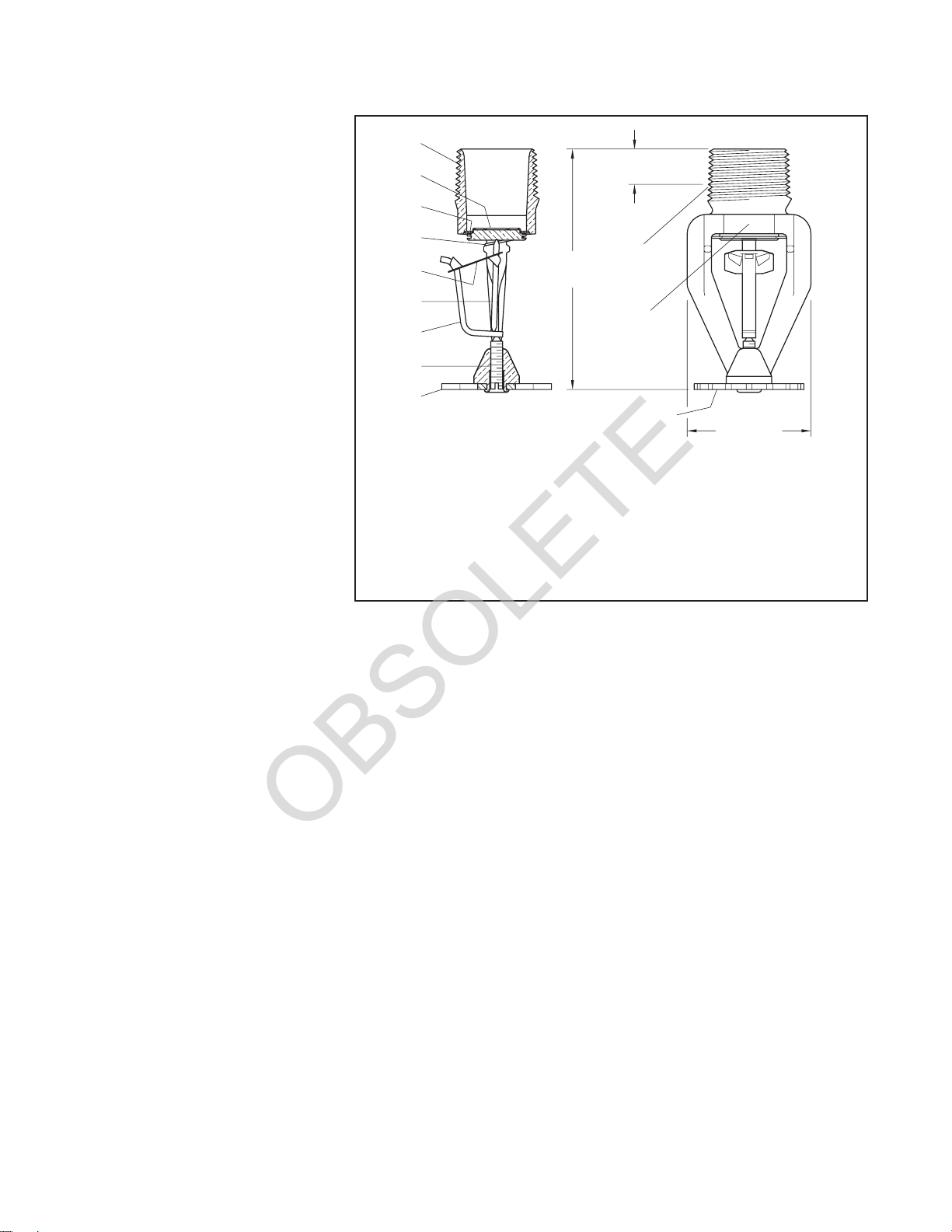
Sprinklers
•The sprinkler pipe threads are to be
checked for damage, e.g., creases
or dents across the thread crest.
Sprinklers having damaged pipe
threads are not to be installed.
Sprinklers having damaged pipe
threads are to be replaced with
sprinklers having pipe threads in
good condition.
•Threaded connections used to in-
TFP314 Page 9 of 16