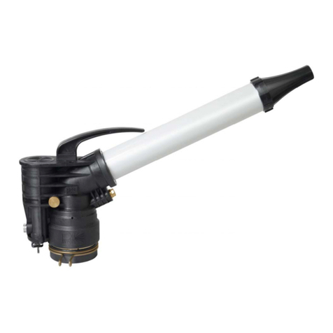
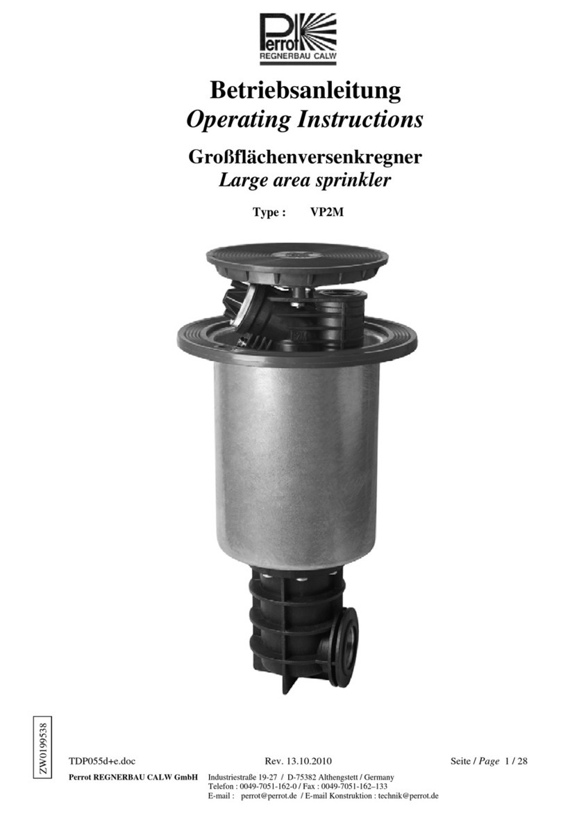
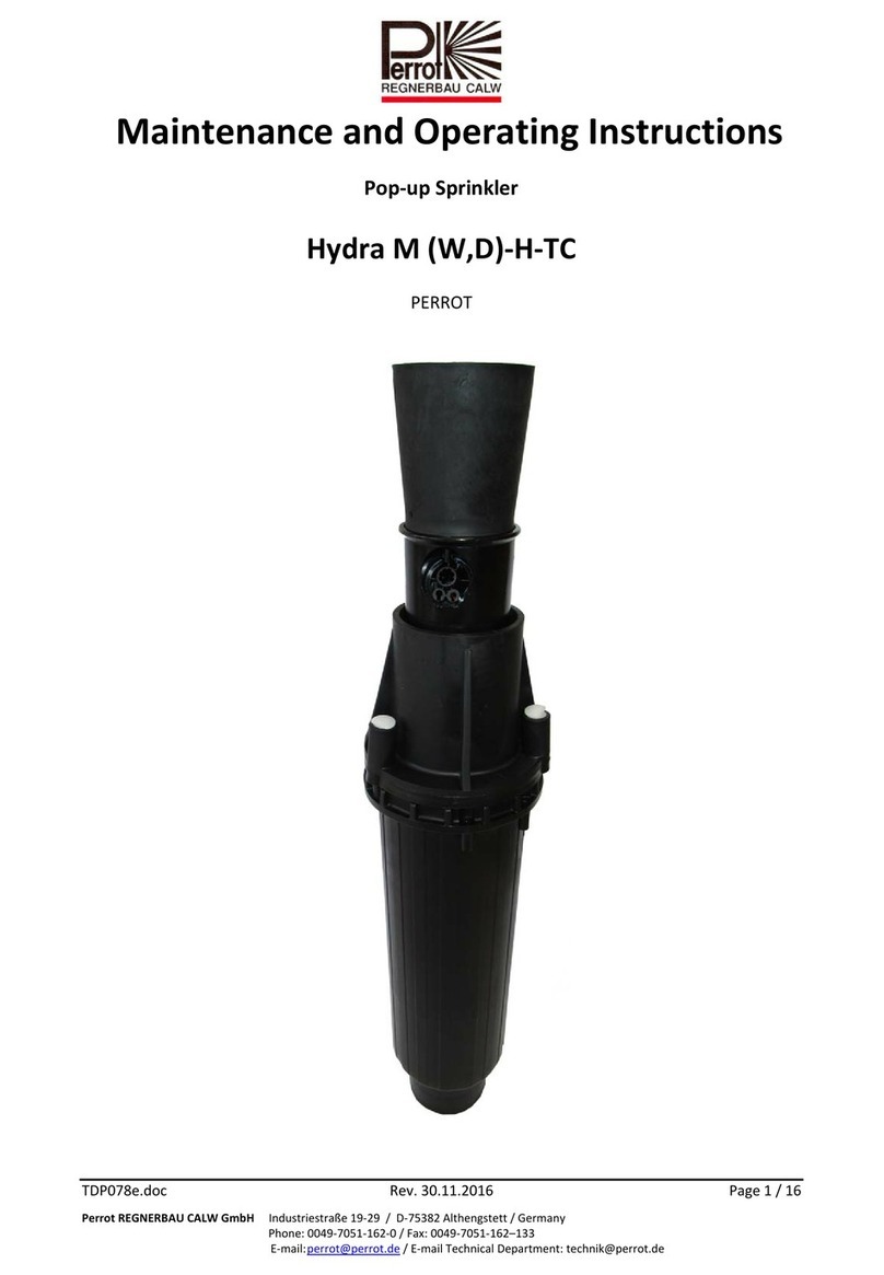
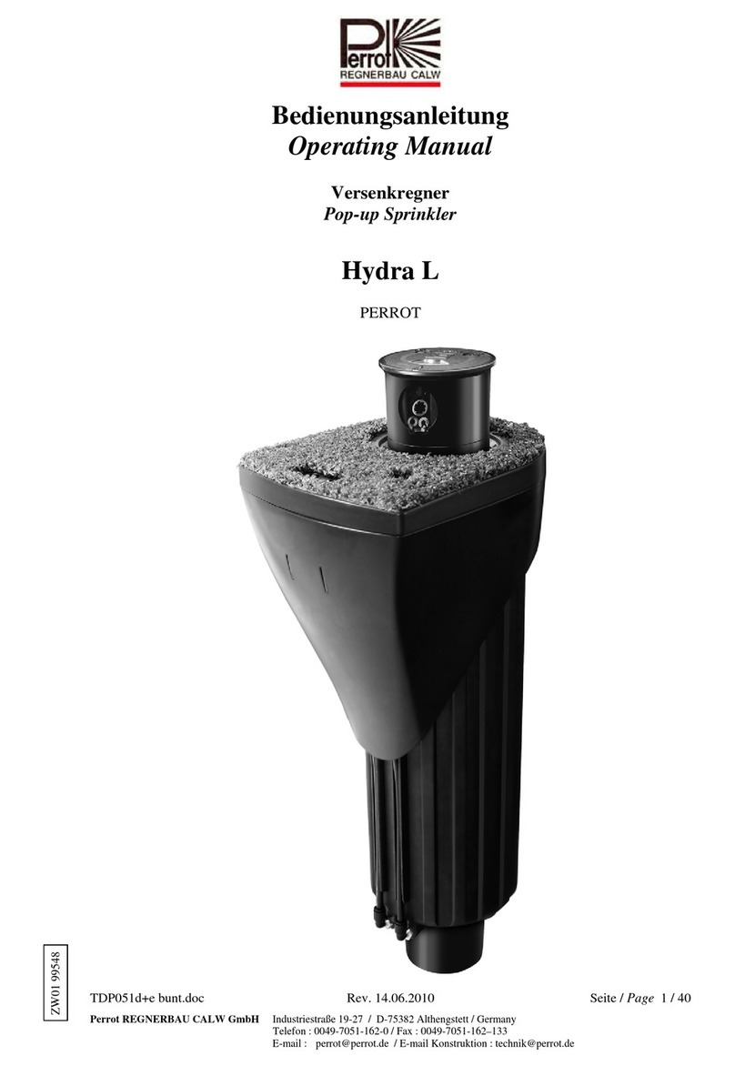
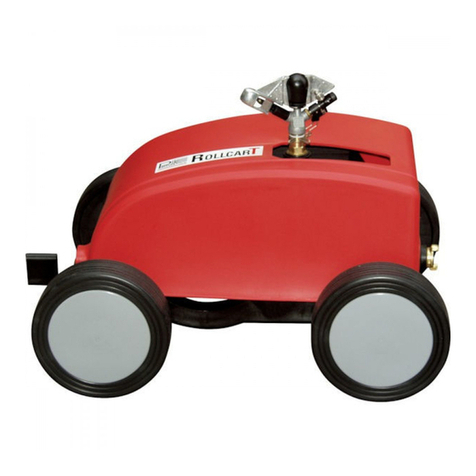
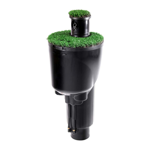
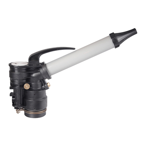
Perrot ZN23-3D Operating and maintenance manual

TDP002d‐e‐f.docRev.26.11.2015Seite‐Page‐Page1/20
PerrotREGNERBAUCALWGmbHIndustriestraße19‐29/D‐75382Althengstett/Germany
Telefon:0049‐7051‐162‐0/Fax:0049‐7051‐162–133
E‐mail:[email protected]/E‐mailKonstruktion:[email protected]
Bedienungs‐undWartungsanleitung
MaintenanceandOperatingInstructions
Manueld’Utilisationetd’Entretien
Großflächenregner
Largeareasprinkler
Canond’Arrosage
Type: ZN23‐3DundZN23‐3W
ZN40‐3DundZN40‐3W
ZN45‐3DundZN45‐3W
Type: ZN23‐3DandZN23‐3W
ZN40‐3DandZN40‐3W
ZN45‐3DandZN45‐3W
Types: ZN23‐3DetZN23‐3W
ZN40‐3DetZN40‐3W
ZN45‐3DetZN45‐3W
PERROT
ZW99531

TDP002d‐e‐f.docRev.26.11.2015Seite‐Page‐Page2/20
PerrotREGNERBAUCALWGmbHIndustriestraße19‐29/D‐75382Althengstett/Germany
Telefon:0049‐7051‐162‐0/Fax:0049‐7051‐162–133
E‐mail:[email protected]/E‐mailKonstruktion:[email protected]
Inhalt
1. Allgemeines
2. Sicherheit
3. Beschreibung
4. Aufstellung
5. Inbetriebnahme/Winterfestmachung
6. Wartung
7. BetriebsstörungundBehebung
1.Allgemeines
Wirgehendavonaus,dassSiesichaufdemGebietderBeregnungauskennen.Deshalbhabenwirdiese
AnleitungkurzgefasstundnurdiejenigenInformationenhineingebracht,dieSieimHinblickaufdie
VerwendungdiesesProduktesunbedingterhaltenmüssen.
Gewährleistungkannnurübernommenwerden,wennderRegnerunterBeachtungdieser
BetriebsanleitungbetriebenwurdeundinnerhalbderGarantiezeitMängelaufweist.
1.1.Verwendungszweck
DerRegnerwirdzurgleichmäßigenVerteilungvonWassereingesetzt.DasWassersolltevorgereinigt
sein,freivongroberundlangfasrigerVerschmutzung.
Max.Wassertemperaturbeträgt50°C.
Max.Umgebungstemperaturbeträgt75°C.
2.Sicherheit
DieseBetriebs‐ undSicherheitsanleitungenthältgrundlegendeHinweise,diebeiMontage,Betrieb,
WartungundInstandsetzungzubeachtensind.DaheristdieseBetriebsanleitungunbedingtvorMontage
undInbetriebnahmevomMonteursowiedemzuständigenFachpersonal/Betreiberzulesen.
EssindnichtnurdieindiesemAbschnitt”Sicherheit”aufgeführtenallgemeinenSicherheitshinweisezu
beachten,sondernauchdieindenanderenAbschnitteneingefügtenspeziellenSicherheitshinweise.
2.1. KennzeichnungvonHinweiseninderBetriebsanleitung
DieindieserBetriebsanleitungenthaltenenSicherheitshinweise,derenNichtbeachtung
GefährdungenvonPersonenhervorrufenkann
sindmitdemallgemeinenGefahrensymbol besondersgekennzeichnet.
BeiSicherheitshinweisen,derenNichtbeachtungGefahrenfürdenRegnerunddessenFunktion
hervorrufenkann,istdasWort
eingefügt.
2.2.GefahrenbeiNichtbeachtungderSicherheitshinweise
DieNichtbeachtungderSicherheitshinweisekannsowohleineGefährdungvonPersonenalsauch
vonUmweltundMaschinezurFolgehaben.DieNichtbeachtungderSicherheitshinweisekannzum
VerlustjeglicherSchadensansprücheführen.
3.Beschreibung
EmpfohlenerBetriebsdruck 5bis7bar
ZulässigerBetriebsdruck 4bis10bar
DerDruckamRegnerdarf10barnichtübersteigen
WeitereDatensieheseparatesDatenblatt

TDP002d‐e‐f.docRev.26.11.2015Seite‐Page‐Page3/20
PerrotREGNERBAUCALWGmbHIndustriestraße19‐29/D‐75382Althengstett/Germany
Telefon:0049‐7051‐162‐0/Fax:0049‐7051‐162–133
E‐mail:[email protected]/E‐mailKonstruktion:[email protected]
4.Montage
GewindeanschlussamRegnerist2½“IG
ZurGewindeabdichtungHanfundDichtungsmassez.B.FermitSpezialverwenden.
ZumAufschraubendesRegnersisteineRohrzangeGröße2½“zuverwenden.
NichtamStrahlrohrdrehen.
AnschlussmuffebiszumAnschlag
einschrauben,damitsichderRegner
währenddesBetriebesnichtlösenkann.
5.Inbetriebnahme
5.1VerstellendesSchwinghebelausschlages
DerSchwinghebelsollca.60°ausschlagen.
DerAusschlagwinkelkannander
AnschlagschraubenachdemLösender
Sechskantmutterreguliertwerden.Die
MarkierungliegtanderInnenseiteder
Schraube.BeikleineremDüsendurchmesser
oderniedrigemDruckschlägtder
Schwinghebelwenigeraus.
MehrAusschlag=hineindrehender
SchraubeinRichtung+.
BeigrößeremDüsendurchmesseroder
hohemDruckschlägtderSchwinghebel
mehraus.
WenigerAusschlag=herausdrehender
SchraubeinRichtung‐.
5.2 EinstellenderBremse
DieBremswirkungkannnachÖffnender
zweiKontermutternverstelltwerden.
StärkereBremswirkung‐hineindrehender
Gewindestifte.
SchwächereBremswirkung–herausdrehen
derGewindestifte.
DieBremswirkungsolltemindestenssostark
sein,dassderRegnerbeimAusschlagendes
Schwinghebelsnichtrückwärtsdreht.
Beidseitiggleichmäßighinein‐bzw.
herausdrehen.
Rohrzange2½“
Anschlagschraube
Sechskantmutter
Gewindestift
Kontermutter
Gewindestift
Kontermutter

TDP002d‐e‐f.docRev.26.11.2015Seite‐Page‐Page4/20
PerrotREGNERBAUCALWGmbHIndustriestraße19‐29/D‐75382Althengstett/Germany
Telefon:0049‐7051‐162‐0/Fax:0049‐7051‐162–133
E‐mail:[email protected]/E‐mailKonstruktion:[email protected]
5.3 Drehfederspannung
DieDrehfederwirdabWerkaufeine
Spannungvon410‐440gr.‐gemessenam
vorderenEndedesSchwinghebels‐
eingestelltunddarfdiesenWertaufkeinen
Fallüberschreiten.NotfallsFeder
nachspannendurchvergrößerndesHakens
amunterenTeildesSchwinghebellagers
(sieheSkizzePkt.6.2.b)
5.4 EinstellungdesaxialenSpielesdesSchwinghebels
Verstellschraubesoweithineindrehen,dassSchwinghebel2‐3mmaxialesSpiel(s)hat.
5.5 EinstellenSektorwinkel
a) KreisberegnungmitSektorregner
Schalthebelhorizontalstellen
b) Sektorberegnung
Schalthebelvertikalstellen
S
p
iel
Verstellschraube

TDP002d‐e‐f.docRev.26.11.2015Seite‐Page‐Page5/20
PerrotREGNERBAUCALWGmbHIndustriestraße19‐29/D‐75382Althengstett/Germany
Telefon:0049‐7051‐162‐0/Fax:0049‐7051‐162–133
E‐mail:[email protected]/E‐mailKonstruktion:[email protected]
c) Sektorwinkeleinstellen
Stufenloseinstellbardurchziehen(nichtdrücken)andemjeweiligenEndedesoberenoder
unterenFederanschlags.
6.Wartung
6.1 Schmierung
Schmierstellen
DieSchmierstellenamSchwinghebelsolltenmonatlichmitkleinenFettmengengeschmiertwerden.
DieSchmierstelleanderLagerungsollte1‐malproJahrabgeschmiertwerden.
DasFettdarfnurmitgeringemDruckeingepresstwerden,dasonstdieAbdeckungdesKugellagers
beschädigtwerdenkönnte.
6.2 EinbaueinesFederlagersmitDrehfeder
a)
DrehfederlagernachSkizzeeinstellenmitdemWinkel45°
Federanschlag
HierVerstellkräfteeinleiten
Federanschlag
Lagerung
Schwinghebel
Drehfeder
Drehfederlager

TDP002d‐e‐f.docRev.26.11.2015Seite‐Page‐Page6/20
PerrotREGNERBAUCALWGmbHIndustriestraße19‐29/D‐75382Althengstett/Germany
Telefon:0049‐7051‐162‐0/Fax:0049‐7051‐162–133
E‐mail:[email protected]/E‐mailKonstruktion:[email protected]
b)
Federende(1)nachSkizzeindieBohrungamSchwinghebeleinführenundFederendeumbiegen.
c)
FederlagermitDrehfedernachSkizzeum225°drehenundZylinderkerbstifteinschlagen.Feder
ggf.nochetwasnachspannen,bisdiekorrekteDrehfederspannungerreichtist(siehePkt.5.3).
6.3 AustauschdesNutringes
SollteanderFührungsbüchseLeckagewasseraustreten,dannistderNutringdefektoderder
Lagernippelisteingelaufen.
a) SechskantmutterlösenundGewindestiftherausschrauben
b) Tellerfedernpaketherausziehen
c) AlleZylinderschraubenlösen,unddieAnschlussmuffeabziehen
d) Prüfe:
LagernippelaufEinlaufstellen
NutringaufAbnützung
ErsetztediebeschädigtenTeile
e) LagernippelkannnurmitMontageschlüsselRT24546demontiertwerden.
ZumAusschraubendesLagernippelsKrümmeramAnschlussgewindezumLagernippelringsum
mitderLötflammegleichmäßigerwärmen.
Zylinderstift
1
Krümmer
Führungsbüchse
Sechskantmutter
Gewindestift
Tellerfedernpaket
Bremsbacken
Scheibe
Lagernippel
Zylinderschraube
Nutring
Stützring
Anschlußmuffe

TDP002d‐e‐f.docRev.26.11.2015Seite‐Page‐Page7/20
PerrotREGNERBAUCALWGmbHIndustriestraße19‐29/D‐75382Althengstett/Germany
Telefon:0049‐7051‐162‐0/Fax:0049‐7051‐162–133
E‐mail:[email protected]/E‐mailKonstruktion:[email protected]
f) VordemEinschraubendesLagernippelsindenKrümmermussGewindegereinigtwerden.
NurandasGewindedesKrümmerswenigeTropfenLoctitegeben
g) NutringundStützringaufdenLagernippelaufstecken
h) Anschlussmuffesoaufstecken,dassNutringnichtbeschädigtwird.
i) Zylinderschraubeneinschrauben
j) TellernfederpacketundGewindestiftwiedermontieren.
(SiehePkt.5.2EinstellungBremse)
AufrichtigeTellerschichtungachten–immer3TellerfederningleicherRichtungmontieren.
6.4 Sektoranschlagverstellen
WennderSektoranschlagabgenütztist,mussdieSenkschraubegelöstundderSektorenanschlagum
ca.45°verdrehtwerden.Senkschraubewiederfestanziehen.
7.BetriebsstörungundBehebung
StörungUrsacheBehebung
Regnerdrehtsichlangsam,erbleibt
beinahestehen.
Bremsbacken
habeneinezugeringeoderzustarke
Bremskraft.
Bremseeinstellen
(siehePunkt5.2)
DerSchwinghebelgreiftnichtmehrin
denStrahlein.
Drehfeder
istgebrochen.
Drehfederaus‐wechseln;
VorspannungderDrehfeder
beachten.(SiehePunkt5.3)
SchlechterRegnerstrahl
GleichrichteristdurchSteineoder,Fasern
verstopft.
Sechskantmutternlösen,Strahlrohr
mitDüseabnehmen,Gleichrichter
herausnehmenundreinigen.
RegnerschaltetimSektorbereich
nichtaufdieandereDrehrichtungum.
Schaltfedergebrochen.
Schaltwalzeabgenützt.
NeueSchaltfedereinbauen.
NeueSchaltwalzeeinbauen.
Sektorwinkelistgrößeralsursprünglich
eingestellt.
FederanschlagistgebrochenNeuenFederanschlageinbauen
MetallgeräuschbeimAnschlagendes
SchwinghebelsandasStrahlrohr.
GummipufferistabgenütztNeuenGummipuffereinbauen.
AnderAnschlussmuffe
tropftWasserab.
DerNutringistabgenützt.
Nutringerneuern;evtl.
Lagernippelerneuern.
(siehePunkt6.3)
WirbehaltenunsÄnderungennachdemStandderTechnikauchohnebesondereAnkündigungvor.
Sektoranschlag
Senkschraube

TDP002d‐e‐f.docRev.26.11.2015Seite‐Page‐Page8/20
PerrotREGNERBAUCALWGmbHIndustriestraße19‐29/D‐75382Althengstett/Germany
Telefon:0049‐7051‐162‐0/Fax:0049‐7051‐162–133
E‐mail:[email protected]/E‐mailKonstruktion:[email protected]
Contents
1. General
2. Safety
3. Description
4. Assembly
5. Commissioning
6. Maintenance
7. Break‐downandeliminationofthedefects
1.General
Wepresumethatyouareexperiencedinthefieldofirrigation.Thereforewehavekeptthisinstructionas
brieflyaspossible,andhaveincludedsuchinformationonly,whichyoumusthavefortheuseofthisproduct.
Aguaranteecanbeacceptedonly,ifthesprinklerhasbeenoperatedinaccordancewiththeseinstructions,
andifthedefectoccurswithintheguaranteeperiod.
1.1.Application
Thesprinklerisusedfortheuniformdistributionofthewater.Thewatershouldbepre‐cleaned,and
freeofcoarseandfibrousimpurities.
Max.watertemperaturewillbe50degreeC.
Max.ambienttemperaturewillbe75degreeC.
2.Safety
Theseoperationandsafetyinstructionsincludebasicremarksandhintsfortheassembly,installation,
operation,maintenance,inspectionandrepair.Forthisreasontheseinstructionsmustbereadbythefitter,
aswellasbythecustomersauthorisedstaff,priortotheinstallationandcommissioning.
Apartfromthegeneralsafetyinstructionsofthisparagraphthespecialsafetyinstructionsincludeinother
paragraphsoftheseoperatinginstructionshavetobeobservedalso.
2.1. Symbolsofhintsgivenintheseoperatinginstructions
Thenon‐observanceofthesafetyinstructionsmentionedintheseoperatinginstructionscan
endangerpersons,are
markedwiththegeneraldangersymbol
especially.
Safetyinstructionswhichcanendangerthesprinkleranditsfunction,ifnotobserved,arespecially
markedandtheword
hasbeeninserted.
2.2.Dangersifthesafetyinstructionsarenotobserved
Non‐observanceofthesafetyinstructionscanendangerpersonsaswellastheenvironmentandthe
sprinkler.Non‐observanceofthesafetyinstructionscanresultinalossofallclaimsforindemnity.
3.Description
Recommendedoperatingpressure 5to7bar
Permissibleoperatingpressure 4to10bar
Thepressureatthesprinklermustnotexceed10bars.
Forfurtherdatapleaserefertotheseparatedataleaflet.

TDP002d‐e‐f.docRev.26.11.2015Seite‐Page‐Page9/20
PerrotREGNERBAUCALWGmbHIndustriestraße19‐29/D‐75382Althengstett/Germany
Telefon:0049‐7051‐162‐0/Fax:0049‐7051‐162–133
E‐mail:[email protected]/E‐mailKonstruktion:[email protected]
4.Assembly
Threadedconnectiononthesprinkleris2½“femalethread.
Forsealingthethread,hempandajointingcompoundhastobeusede.g.Fermitspecial
Toscrewonthesprinkler,alwaysuseapipewrenchsize2½“.
Donotturnthesprinklerbyusingthejetpipe.
Screwontheconnectionsocketuptothe
detent,sothatthesprinklercannotunscrew
itselfduringoperation.
5.Commissioning
5.1Adjustmentoftheimpactleverstops
Theimpactleverhastodeflectapprox.
60degrees.Theangleofdeflectioncanbe
regulatedatthestopscrew,afterthe
hexagonnuthasbeenloosened.Themarking
isontheinsideofthescrew(bolt).Ifthe
sprinklerisequippedwithnozzlesthathavea
smallerdiameter,oriftheoperating
pressureissomewhatlower,thentheimpact
leverwillhaveasmallerangleofdeflection.
Largerdeflection=turnthescrewinthe
direction+.
Ifbiggernozzlesareused,orifthepressureis
high,theangleofdeflectionwillbelarger.
Lessdeflection=turnthescrewinthe
direction‐.
5.2 Settingthebrake
Thebrakingeffectcanbeset,aftertheboth
locknutshavebeenloosened.
Morebrakingeffect,tightenthegrub
screw.Lessbrakingeffect,loosenthegrub
screw.
Thebrakingeffectshouldbesuchthatthe
sprinklerdoesnotturnbackwards,during
rotationoftheimpactlever.
Loosenortightenbothgrubscrewsinthe
sameway.
Pipewrench2½“
Stopscrew
Hexnut
Locknut
Grubscrew
Locknut
Grubscrew

TDP002d‐e‐f.docRev.26.11.2015Seite‐Page‐Page10/20
PerrotREGNERBAUCALWGmbHIndustriestraße19‐29/D‐75382Althengstett/Germany
Telefon:0049‐7051‐162‐0/Fax:0049‐7051‐162–133
E‐mail:[email protected]/E‐mailKonstruktion:[email protected]
5.3Tensionofthetorsionspring
Thetorsionspringissetatatensionof410‐
440gr.inthefactory.Thistensionis
measuredatthefrontendoftheimpact
lever,andmustundernocircumstancesbe
exceeded.Ifnecessary,tightenthespringby
enlargingthehookatthelowerpartofthe
impactleverbearing(seesketchunderpoint
6.2.b).
5.4 Settingtheaxialplayoftheimpactlever
Tightentheadjustingscrewtosuchanextent,thattheimpactleverhasanaxialplay(s)of2‐3mm
5.5 Settingthepartcircleangle
a)Fullcirclemovementwithapartcirclesprinkler
Flip‐upthepintoahorizontalposition
b.)Partcircleirrigation
Placethetrippininaverticalposition.
Axialplay
Adjustingscrew

TDP002d‐e‐f.docRev.26.11.2015Seite‐Page‐Page11/20
PerrotREGNERBAUCALWGmbHIndustriestraße19‐29/D‐75382Althengstett/Germany
Telefon:0049‐7051‐162‐0/Fax:0049‐7051‐162–133
E‐mail:[email protected]/E‐mailKonstruktion:[email protected]
c.)Settingthepartcircleangle
Infinitelyvariablebypulling(notpressing)therelevantendoftheupperorlowerspringstop.
6.Maintenance
6.1 Lubrication
Lubricationpoints
Thelubricationpointsattheimpactlevershouldbelubricatedwithlittlequantitiesofgrease.
Thelubricationpointatthebearingshouldbelubricatedonceayear.Thegreasemaybepressedin
onlyataverylowpressure,inordernottodamagethecoveroftheballbearing.
6.2 Fittingaspringbearingwithtorsionspring
a)
Set torsion spring bearing acc. to sketch with an angle of 45 degree.
Stringstop
Pullthespringstophere
Stringstop
Bearing
Impactlever
Torsion spring
Springbearing

TDP002d‐e‐f.docRev.26.11.2015Seite‐Page‐Page12/20
PerrotREGNERBAUCALWGmbHIndustriestraße19‐29/D‐75382Althengstett/Germany
Telefon:0049‐7051‐162‐0/Fax:0049‐7051‐162–133
E‐mail:[email protected]/E‐mailKonstruktion:[email protected]
b)
Placetheendofthespring(1)intothedrilledholeontheimpactleverandbentovertheendof
thespring.Seesketch
c)
Turnthespringbearingwiththetorsionspringby225degreeanddrive‐inthecylindricalnotched
pin.Ifnecessaryre‐tightenspring,untilyougotthecorrecttension(seeitem5.3).
6.3 Exchangingthegroovedring
Shouldtherebealeakageattheguidebush,thenthegroovedringisdefectorthebearingnipplehas
run‐inmarks.
a) Loosenhex.nutandunscrewthegrubscrew
b) Pulloutthecupspringpack
c) Loosenallcylindricalscrews,andpullofftheconnectingsocket.
d) Test:
Ifbearingnipplehasrun‐inmarks
Ifgroovedringisworn.
Replacethedefectiveparts
Pin
1
Elbow
Guidebush
He.xnut
Grubsrew
Cupspringpac
k
Brakeshoe+pin
Shim
Bearingnipple
Cyl.screw
Grovedring
Trustring
Connectionsocket

TDP002d‐e‐f.docRev.26.11.2015Seite‐Page‐Page13/20
PerrotREGNERBAUCALWGmbHIndustriestraße19‐29/D‐75382Althengstett/Germany
Telefon:0049‐7051‐162‐0/Fax:0049‐7051‐162–133
E‐mail:[email protected]/E‐mailKonstruktion:[email protected]
e) Unscrewthebearingnipple,bywarminguptheelbowattheconnectionthreadtothebearing
nipplerightround,byusingablowpipeflame(solderingtorch).
f) Priortoscrewinginthebearingnippleintotheelbow,thethreadhastobecleaned.
PutafewdropsofLoctiteonthethreadoftheelbow
g) Replacethegroovedringandthethrustringonthebearingnipple.
h) Re‐fittheconnectingsocketinsuchaway,thatthegroovedringisnotdamaged.
i) Screwinallcylindricalscrews
j) Reassemblethecupspringpackandthegrubscrew
(Seeadjustmentofbrakepoint5.2)
6.4 Adjustmentofthetripstops
Ifthetripstopisworn,thesunkenscrewmustbeloosenedandthetripstophastoberotatedby
approx.45degree.Re‐tightenthetripbolt.
7.Break‐downandeliminationofthedefects
FaultsCauseElimination
Sprinklerturnsslowly,italmoststopsThebrakeshoeshaveatoolittleortoo
strongabrakepowerAdjustbrake(seepoint5.2)
Theimpactleverdoesnotenterthejet
streamanymoreTorsionspringisbroken
ReplacetorsionspringObservethe
pre‐tensionofthetorsionspring(see
point5.3)
BadwaterjetThestreamstraightenedisblockedby
stonesorfibrousimpurities
Loosenhex.nut
Takeoffthejetpipewiththenozzle,
takeoutthestreamstraightenedand
cleanit.
Thesprinklerdoesnotswitchoverthe
reversedirectioninthepartcirclerangeTripspringisbroken.TriprolleriswornReplacethetripspringFitnewtrip
roller
Thepartcircleangleislargerthanset
originally.SpringstopisbrokenReplacespringstop
Metallicnoisewhentheimpactleverhits
thejetpipeTherubberbufferiswornReplacerubberbuffer
WaterleaksattheconnectionsocketThegroovedringisworn
Replacegroovedring.Perhapsthe
bearingnipplehastobereplacedtoo,
(seepoint6.3)
Subjecttochangewithoutpriornotice.
Tripstop
Sunkenscrew

TDP002d‐e‐f.docRev.26.11.2015Seite‐Page‐Page14/20
PerrotREGNERBAUCALWGmbHIndustriestraße19‐29/D‐75382Althengstett/Germany
Telefon:0049‐7051‐162‐0/Fax:0049‐7051‐162–133
E‐mail:[email protected]/E‐mailKonstruktion:[email protected]
Sommaire
1. Considérationsgénérales
2. Règlesdesécurité
3. Pressiond’utilisation
4. Installation
5. Réglageducanon
6. Entretien
7. Incidentsetdépannages
1.Considérationsgénérales
Cemanuels’adresseàdesutilisateursayantunecertainepratiquedel’irrigation.Enconséquence,nousavonsrédigé
cesinstructionsdemanièresuccinctes,etn’avonsinclusquelesinformationsstrictementnécessairesàlabonne
utilisationdecetéquipement.
Lagarantieduconstructeurs’appliqueuniquementsilecanonaétéutiliséconformémentauxinstructionsdonnées
dansleprésentmanuel,etdanslalimitedelapériodedegarantieaccordéeparleconstructeur.
1.1.Conditionsd’utilisation
Ilestimportantdevérifierlaqualitédel’eauutiliséedansl’alimentationducanon,afind’obtenirune
distributionhomogènedel’irrigation.L’eauutiliséedoitêtresipossiblepré‐filtrée,afind’éliminerlesparticules
lesplusgrossières:graviers,algues,débrisetimpuretésdiverses.
Températuremaximaledel’eaud’arrosage:50°C
Températuremaximaled’utilisation:75°C(T°del’airambiant)
2.Règlesdesécurité
Leprésentdocumentreprendlesinstructionsgénéralesetlesconseilsdesécuritépourl’installation,lemontage,
l’utilisationetl’entretiendescanonsd’arrosage.Ilestdoncfortementrecommandéquecesinstructionssoientluespar
tousceuxquiontàutilisercetéquipement:installateurs,monteurs,utilisateursetréparateurs,etcelaavanttoute
installationouutilisation.
Enplusdesrèglesgénéralesdesécuritédonnéesdansceparagraphe,d’autresinstructionsspécifiquesdesécuritésont
donnéesdanslesautresparagraphesdecemanuel;cesrèglesdesécuritédoiventêtresuiviesavecrigueur.
2.1. Symbolesd’attentionetdeconseilutilisésdanscemanuel
Danslesexplicationsdonnéesci‐après,touteslesrecommandationsdesécuritésontsignaléesparlessymboles
suivants:
Règlesdesécuritépouvantmettreendangerlespersonnesencasdenonrespectdecesrègles:
Utilisationdusymbolegénéraldedanger
dangerspécifique.
Règlesdesécuritépouvantmettreendangerlecanonetsesperformancessiellesnesontpasrespectées:elles
sontparticulièrementsignalées,
etlesymbole aétéinséré.
2.2.Dangersencourussilesrèglesdesécuriténesontpasobservées
Lanon‐observancedesrèglesdesécuritépeutmettreendangerl’intégritédespersonnes,ainsiquelabonne
performanceducanonoul’équilibredel’environnement.Lenon‐respectdecesrèglespeutégalement
entraînerl’annulationdesconditionsdelagarantie.
3.Pressiond’utilisation
Plagedepressiond’utilisationrecommandée 5à7bar
Pressionminimaleetmaximaled’utilisation 4à10bar
Lapressionmaximaleaucanonnedoitpasexcéder10bars.
Pourlescaractéristiquestechniquesdepression,débitetportée,seréféreràlafichetechniquespécifiqueducanonZN.

TDP002d‐e‐f.docRev.26.11.2015Seite‐Page‐Page15/20
PerrotREGNERBAUCALWGmbHIndustriestraße19‐29/D‐75382Althengstett/Germany
Telefon:0049‐7051‐162‐0/Fax:0049‐7051‐162–133
E‐mail:[email protected]/E‐mailKonstruktion:[email protected]
4. Installation
LecanonZNaunebasedefixationtaraudée2”½.
Pourlemontageducanonsurlesupport,utiliserunproduitd’étanchéité:filasseetpâteàjoint,téflonliquideou
enruban.NousrecommandonsleFermitspécial.
Pourassurerlemontagedesfiletages,utiliserunecléàgriffed’ouverture2”½.
Nepastournerlecanonenutilisantlefûtdel’arroseur.
Visseretbloquerlesocledebasesurlesupport
fileté,defaçonàcequecanonnepuissepasse
dévisserdurantlefonctionnement.
5. Réglage du canon
5.1 Ajustement de l’angle de déflexion du bras moteur
Lebrasmoteurdoitavoirunanglededéflexion
d’environ60degrés.Cetanglepeutêtreajusté
parlabutéed’arrêt,aprèsavoirdesserrél’écrou
hexagonaldeblocage.Lemarquagepour
l’ajustementsetrouveàl’intérieurdelabutée
d’arrêt(écrou).Silecanonestéquipédebusesde
petitdiamètre,ousilapressionde
fonctionnementestplusfaible,lebrasmoteur
auraunanglededéflexionplusréduit.
Anglededéflectionpluslarge=tournerla
butéed’arrêtdansladirection+.
Sil’onutilisedesbusesdeplusgranddiamètre,
ousilapressionestplusélevée,l’anglede
déflexionseraplusimportant.
Anglededéflectionplusréduit=tournerla
butéed’arrêtdansladirection‐.
5.2 Réglage du frein
L’effetdefreinagepeutêtreajustéaprèsavoir
desserrélesdeuxvisdeblocage.
Freinageplusimportant:resserrerlesvisde
réglage.
Freinagemoinsimportant:desserrerlesvisde
réglage.
Lefreindoitêtreajustédefaçonàcequele
canonnereviennepasenarrièreaveclebras
moteur.Lesdeuxvisderéglagedoiventêtre
ajustéesdemanièreéquivalente.
Cléàgriffe2½“
Butéed‘arrêt
Écrouhexagonale
deblocage
visdeblocage
visderéglage
visdeblocage
visderéglage

TDP002d‐e‐f.docRev.26.11.2015Seite‐Page‐Page16/20
PerrotREGNERBAUCALWGmbHIndustriestraße19‐29/D‐75382Althengstett/Germany
Telefon:0049‐7051‐162‐0/Fax:0049‐7051‐162–133
E‐mail:[email protected]/E‐mailKonstruktion:[email protected]
5.3 Réglageduressortdetorsion
Leressortdetorsiondubrasmoteurestrégléen
usineàlatensionde410‐440gr.Cettetension
peutêtremesuréeparuntensiomètreà
l’extrémitédubrasmoteur,etnedoitjamais
excéderlatensionfixéeenusine.Sinécessaire,
onpeutaugmenterlatensionduressortde
torsionenleraccourcissantàlabaseduguide
d’ancrageduressort(voircroquisaupar.6.2/b).
5.4 Ajustementdujeudel’axedubrasmoteur
Resserrerlavisderéglage,afinquelejeud’axe(s)dubrasmoteursoitde2‐3mm.
5.5 Réglagedel’angledusecteurd’arrosage
a)Arrosageenpleincercleavecuncanonàsecteur
Releverledoigtd’inversionenpositionhorizontale
b)Arrosageensecteur
Mettreledoigtd’inversionenpositionverticale
Jeud'axe
Visderéglage

TDP002d‐e‐f.docRev.26.11.2015Seite‐Page‐Page17/20
PerrotREGNERBAUCALWGmbHIndustriestraße19‐29/D‐75382Althengstett/Germany
Telefon:0049‐7051‐162‐0/Fax:0049‐7051‐162–133
E‐mail:[email protected]/E‐mailKonstruktion:[email protected]
c)Réglagedel’angledusecteurd’arrosage
Réglagepourn’importequellevaleurd’angleenécartant(nepaspresser)lesbranchesduressortd’arrêt
supérieurouinférieur.
6. Entretien
6.1Graissage
Pointsdegraissage
Lespointsdegraissagedubrasmoteurdoiventêtrelégèrementmaisrégulièrementgraissés,suivantla
fréquenced’utilisation.
Leroulementdebaseducanondoitêtregraisséunefoisl’an.Lagraissedoitêtre
introduiteàfaiblepression,afindenepasendommagerlecouvercledu
roulementàbille.
6.2Miseenplaceduguided’ancrageetduressortdetorsion
a)
Positionnerleguided’ancrageetleressortdetorsionselonlecroquis,avecunanglede45degrés.
Ressortd'arrêt
Écarterlesbranchesduressort
Ressortd'arrêt
Graisseurdu
roulementdebase
brassmoteur
Ressort de tors
ion
Guided'ancrage

TDP002d‐e‐f.docRev.26.11.2015Seite‐Page‐Page18/20
PerrotREGNERBAUCALWGmbHIndustriestraße19‐29/D‐75382Althengstett/Germany
Telefon:0049‐7051‐162‐0/Fax:0049‐7051‐162–133
E‐mail:[email protected]/E‐mailKonstruktion:[email protected]
b)
Passerleboutinférieurduressort(1)dansletroupercédubrasmoteur,etplierl’extrémitéduressort.Voir
croquisci‐dessus.
c)
Tournerleguided’ancrageetleressortdetorsionde225degrésetfixerlagoupilled’arrêt.Sinécessaire,
resserrerleressortjusqu’àl’obtentiond’unetensioncorrecte(voirpar.5.3).
6.3Remplacementdumécanismedebase
Encasdefuiteàlabaseducanon,ilfautdémonteretvérifierl’étatdujointàlèvreetdumanchondebase.
a) Desserrerlavishexagonaledeblocageetlavisderéglagedufrein.
b) Retirerl’ensembledesressortsdefrein
c) Desserrertouteslesviscylindriquesetdégagerlabasedefixation
d) Vérifier:
silemanchondebaseportedestracesd’usure
silejointàlèvreesthorsd’usage
Remplacerlapièceusagée
Goupilled'arrêt
1
Palierderoulement
Vishexagonale
Visderéglagedufrein
Ensembledesressortsde
frein
Coussinetdefrein+goupille
Rondelled'appui
Manchondebase
Viscylindrique
Jointàlèvre
Palierdujoint
Basedefixation
Coude

TDP002d‐e‐f.docRev.26.11.2015Seite‐Page‐Page19/20
PerrotREGNERBAUCALWGmbHIndustriestraße19‐29/D‐75382Althengstett/Germany
Telefon:0049‐7051‐162‐0/Fax:0049‐7051‐162–133
E‐mail:[email protected]/E‐mailKonstruktion:[email protected]
e) Avantdedévisserlemanchondebaseducorpscoudéducanon,chaufferlégèrementlefiletageavecla
flammed’unelampeàsouder(flammejauneclair)pourramollirlapâted’étanchéité.
f) Avantderevisserlemanchondebasesurlecorpsducanon,nettoyersoigneusementlefiletage.
appliquerunpeudeLoctitesurlefiletageducorpsducanon.
g) Replacerlejointàlèvreetsarondelledebutéesurlemanchondebase.
h) Re‐ajusterlabasedefixationenveillantànepasabîmerlejointàlèvre.
i) Resserrertouteslesviscylindriques.
j) Remettreenplacel’ensembledesressortsdefrein,etréglerlefrein.
(Voir“Réglagedufrein”–Par.5.2)
6.4Ajustementdelabutéederetour
Silabutéederetourestusée,ilfautdévisserlavisdeblocageetfairepivoterlabutéed’environ45degrés.
Resserrerlavisdeblocage.
7. Incidentsetdépannages
IncidentsCausesDépannages
Lecanontournelentement,
ous’arrêtepresque
Lefreinestmalréglé:trop
serréoutroprelâché
Réglerleserragedu
frein(voirpar.5.2)
Lebrasmoteurnepénètreplusdansle
jetd’eauLeressortdetorsiondubrasmoteurestcassé
Remplacerleressortdetorsion.
Vérifierlatensionduressortde
torsion(voirpar.5.3)
Lejetd’arrosagen’estpasrégulier
Leguidejetducanonestbouchépardes
impuretés(graviersoufibresvégétales)
Desserrerlesvishexagonales,
démonterlecorpsducanon,retirerle
guide‐jetetlenettoyer
Lecanonnerevientpasenarrière,dans
l’utilisationdel’arrosageensecteur
Leressortdudoigtd’inversionestcassé
Labilledudoigtd’inversionestusée
Remplacerleressort
Mettreunenouvellebille
L’angledusecteurd’arrosageestplus
grandqueleréglageinitialUndesressortsd’arrêtestcasséRemplacerleressortcassé
Bruitmétalliquequandlebrasmoteur
frappelecorpsducanon
L’amortisseurencaoutchoucdelabutée
d’arrêtestusé
Remplacerl’amortisseuren
caoutchouc
Fuited’eauàlabaseducanonLejointàlèvreestusé
Remplacerlejointàlèvre.Ilserapeut‐
êtrenécessairederemplacerle
manchondebase(voirpar.6.3)
Noticetechniquesusceptibled’êtremodifiéesanspréavis
Butéederetour
Visdeblocage

TDP002d‐e‐f.docRev.26.11.2015Seite‐Page‐Page20/20
PerrotREGNERBAUCALWGmbHIndustriestraße19‐29/D‐75382Althengstett/Germany
Telefon:0049‐7051‐162‐0/Fax:0049‐7051‐162–133
E‐mail:[email protected]/E‐mailKonstruktion:[email protected]
FürweitereInformationenstehenwirIhnengernezurVerfügung!
Weremainatyourfulldisposalforanyfurtherinformationyoumayrequire!
Nousrestonsàvotredispositionpourtouteinformationsupplémentaire!
REGNERBAUCALWGmbH
Industriestrasse19‐29
75382Althengstett/Germany
Tel.+49/7051/162‐0
Fax.+49/7051/162‐133
http://www.perrot.de
ZW99531
This manual suits for next models
5
Table of contents
Languages:
Other Perrot Irrigation System manuals

Perrot
Perrot Hydra L User manual

Perrot
Perrot LVZX 30 User manual

Perrot
Perrot P2M Operating and maintenance manual

Perrot
Perrot VP3 VAC Operating and maintenance manual

Perrot
Perrot Hydra M Operating and maintenance manual

Perrot
Perrot P2S Operating and maintenance manual

Perrot
Perrot LVZE 22-1 VAC Operating and maintenance manual

Perrot
Perrot ZX30 Series User manual

Perrot
Perrot VP2M User manual

Perrot
Perrot Hydra M VAC User manual