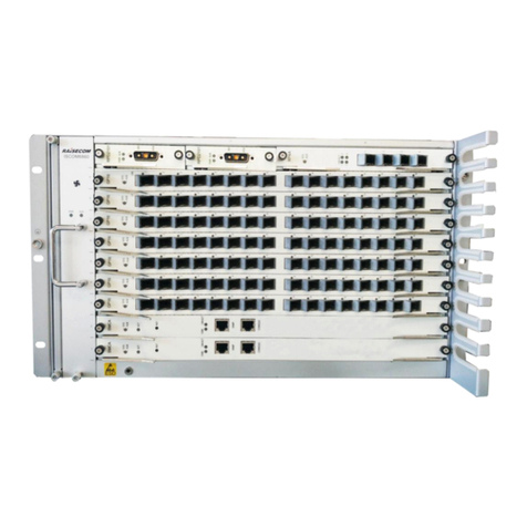
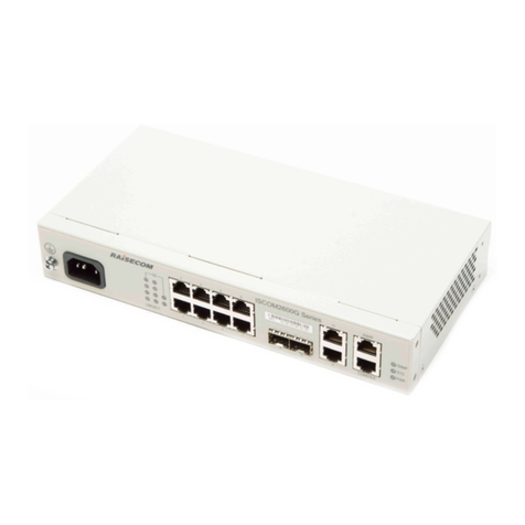
Raisecom iTN2100 Guide

iTN2100 (P100R002)
Hardware Description
(Rel_01)
www.raisecom.com

Raisecom Technology Co., Ltd. provides customers with comprehensive technical support and services. For any
assistance, please contact our local offices or company headquarters.
Website: http://www.raisecom.com
Tel: 8610-82883305
Fax: 8610-82883056
Email: export@raisecom.com
Address: Building 2, No. 28, Shangdi 6th Street, Haidian District, Beijing, P.R.China
Postal code: 100085
-----------------------------------------------------------------------------------------------------------------------------------------
Notice
Copyright ©2013
Raisecom
All rights reserved.
No part of this publication may be excerpted, reproduced, translated or utilized in any form or by any means,
electronic or mechanical, including photocopying and microfilm, without permission in Writing from Raisecom
Technology Co., Ltd.
is the trademark of Raisecom Technology Co., Ltd.
All other trademarks and trade names mentioned in this document are the property of their respective holders.
The information in this document is subject to change without notice. Every effort has been made in the
preparation of this document to ensure accuracy of the contents, but all statements, information, and
recommendations in this document do not constitute the warranty of any kind, express or implied.

Raisecom
iTN2100 (P100R002) Hardware Description
Preface
Raisecom Technology Co., Ltd.
i
Preface
Objectives
This manual describes the integrated equipment, components, and cables of the iTN2100,
including hardware features, components, functions of each component, cables, and
specifications of these cables. To have a quick grasp of the iTN2100, please read this manual
carefully.
Versions
The following table lists the product versions related to this document.
Product Name
Product version
Chassis version
Software version
iTN2100
P100R002
C.01 or later
iTN2100-NMS-
C_V4.23 or later
Conventions
Symbol conventions
The symbols that may be found in this document are defined as follows.
Symbol
Description
Indicates a hazard with a medium or low level of risk which, if
not avoided, could result in minor or moderate injury.
Indicates a potentially hazardous situation that, if not avoided,
could cause equipment damage, data loss, and performance
degradation, or unexpected results.
Provides additional information to emphasize or supplement
important points of the main text.

Raisecom
iTN2100 (P100R002) Hardware Description
Preface
Raisecom Technology Co., Ltd.
ii
Symbol
Description
Indicates a tip that may help you solve a problem or save time.
General conventions
Convention
Description
Times New Roman
Normal paragraphs are in Times New Roman.
Arial
Paragraphs in Warning, Caution, Notes, and Tip are in Arial.
Boldface
Names of files, directories, folders, and users are in boldface.
For example, log in as user root.
Italic
Book titles are in italics.
Lucida Console
Terminal display is in Lucida Console.
Change history
Updates between document versions are cumulative. Therefore, the latest document version
contains all updates made to previous versions.
Issue 01 (2013-02-16)
Initial commercial release

Raisecom
iTN2100 (P100R002) Hardware Description
Contents
Raisecom Technology Co., Ltd.
iii
Contents
1 Overview.........................................................................................................................................1
1.1 Introduction......................................................................................................................................................1
1.2 Components......................................................................................................................................................1
2 Chassis.............................................................................................................................................5
2.1 Structure...........................................................................................................................................................5
2.2 Slots..................................................................................................................................................................7
2.3 VC4 and GE distribution..................................................................................................................................7
2.4 Specifications...................................................................................................................................................8
3 Fan....................................................................................................................................................9
3.1 Functions..........................................................................................................................................................9
3.2 Appearance.......................................................................................................................................................9
3.3 LEDs ..............................................................................................................................................................10
3.4 Specifications.................................................................................................................................................10
4 Power supplies.............................................................................................................................12
4.1 SUB-PWRII-DC/DC-300...............................................................................................................................13
4.1.1 Appearance and functions.....................................................................................................................13
4.1.2 Slots ......................................................................................................................................................13
4.1.3 LEDs.....................................................................................................................................................14
4.1.4 Specifications........................................................................................................................................14
4.2 SUB-PWRM-DC............................................................................................................................................16
4.2.1 Appearance and functions.....................................................................................................................16
4.2.2 Slots ......................................................................................................................................................16
4.2.3 LEDs.....................................................................................................................................................17
4.2.4 Specifications........................................................................................................................................17
4.3 SUB-PWRM-AC............................................................................................................................................19
4.3.1 Appearance and functions.....................................................................................................................19
4.3.2 Slots ......................................................................................................................................................19
4.3.3 Interfaces...............................................................................................................................................20
4.3.4 LEDs.....................................................................................................................................................20
4.3.5 Specifications........................................................................................................................................21
5 NMS card ......................................................................................................................................23

Raisecom
iTN2100 (P100R002) Hardware Description
Contents
Raisecom Technology Co., Ltd.
iv
5.1 iTN2100-NMS ...............................................................................................................................................24
5.1.1 Appearance and functions.....................................................................................................................24
5.1.2 Slots ......................................................................................................................................................24
5.1.3 Interfaces...............................................................................................................................................25
5.1.4 Buttons..................................................................................................................................................26
5.1.5 LEDs.....................................................................................................................................................26
5.1.6 Alarms...................................................................................................................................................27
5.1.7 Specifications........................................................................................................................................27
6 SDH aggregation card ................................................................................................................28
6.1 OPCOM3500E-2STM1/4-M..........................................................................................................................29
6.1.1 Appearance and functions.....................................................................................................................29
6.1.2 Slots ......................................................................................................................................................29
6.1.3 Interfaces...............................................................................................................................................30
6.1.4 LEDs.....................................................................................................................................................31
6.1.5 DIP switch.............................................................................................................................................32
6.1.6 Alarms...................................................................................................................................................32
6.1.7 Specifications........................................................................................................................................34
7 SDH tributary cards....................................................................................................................35
7.1 OPCOM3500E-STM1-S................................................................................................................................36
7.1.1 Appearance and functions.....................................................................................................................36
7.1.2 Slots ......................................................................................................................................................36
7.1.3 Interfaces...............................................................................................................................................37
7.1.4 LEDs.....................................................................................................................................................38
7.1.5 Alarms...................................................................................................................................................39
7.1.6 Specifications........................................................................................................................................39
7.2 OPCOM3500E-4STM1-S..............................................................................................................................41
7.2.1 Appearance and functions.....................................................................................................................41
7.2.2 Slots ......................................................................................................................................................41
7.2.3 Interfaces...............................................................................................................................................42
7.2.4 LEDs.....................................................................................................................................................42
7.2.5 Alarms...................................................................................................................................................43
7.2.6 Specifications........................................................................................................................................44
8 Ethernet aggregation card..........................................................................................................45
8.1 iTN2100-NTU-4GF .......................................................................................................................................46
8.1.1 Appearance and functions.....................................................................................................................46
8.1.2 Slots ......................................................................................................................................................46
8.1.3 Interfaces...............................................................................................................................................47
8.1.4 LEDs.....................................................................................................................................................47
8.1.5 Specifications........................................................................................................................................48
9 Ethernet switching card .............................................................................................................49

Raisecom
iTN2100 (P100R002) Hardware Description
Contents
Raisecom Technology Co., Ltd.
v
9.1 iTN2100-PTU-4GE........................................................................................................................................50
9.1.1 Appearance and functions.....................................................................................................................50
9.1.2 Slots ......................................................................................................................................................50
9.1.3 Interfaces...............................................................................................................................................51
9.1.4 LEDs.....................................................................................................................................................51
9.1.5 Specifications........................................................................................................................................52
10 Ethernet access cards ................................................................................................................53
10.1 iTN2100-16GF.............................................................................................................................................54
10.1.1 Appearance and functions...................................................................................................................54
10.1.2 Slots ....................................................................................................................................................55
10.1.3 Interfaces.............................................................................................................................................55
10.1.4 LEDs...................................................................................................................................................56
10.1.5 Specifications......................................................................................................................................56
10.2 iTN2100-8FX...............................................................................................................................................58
10.2.1 Appearance and functions...................................................................................................................58
10.2.2 Slots ....................................................................................................................................................59
10.2.3 Interface ..............................................................................................................................................59
10.2.4 LEDs...................................................................................................................................................60
10.2.5 Specifications......................................................................................................................................60
10.3 iTN2100-2IGC.............................................................................................................................................62
10.3.1 Appearance and functions...................................................................................................................62
10.3.2 Slots ....................................................................................................................................................62
10.3.3 Interface ..............................................................................................................................................63
10.3.4 LEDs...................................................................................................................................................64
10.3.5 Specifications......................................................................................................................................65
10.4 OPCOM3500E-4FX.....................................................................................................................................66
10.4.1 Appearance and functions...................................................................................................................66
10.4.2 Slots ....................................................................................................................................................66
10.4.3 Interfaces.............................................................................................................................................67
10.4.4 LEDs...................................................................................................................................................67
10.4.5 DIP swtiches .......................................................................................................................................68
10.4.6 Specifications......................................................................................................................................68
10.5 OPCOM3500E-8FX.....................................................................................................................................69
10.5.1 Appearance and functions...................................................................................................................69
10.5.2 Slots ....................................................................................................................................................69
10.5.3 Interfaces.............................................................................................................................................70
10.5.4 LEDs...................................................................................................................................................70
10.5.5 Specifications......................................................................................................................................71
11 Clock card ...................................................................................................................................72
11.1 iTN2100-TSU...............................................................................................................................................73

11.1.1 Appearance and functions ...................................................................................................................73


Raisecom
iTN2100 (P100R002) Hardware Description
Contents
Raisecom Technology Co., Ltd.
vi
11.1.2 Slots.....................................................................................................................................................73
11.1.3 Interfaces.............................................................................................................................................74
11.1.4 LEDs ...................................................................................................................................................75
11.1.5 Specifications......................................................................................................................................76
12 TDMoP card ...............................................................................................................................77
12.1 iTN2100-CES-16E1T1-BL..........................................................................................................................78
12.1.1 Appearance and functions...................................................................................................................78
12.1.2 Slots ....................................................................................................................................................78
12.1.3 Interfaces.............................................................................................................................................79
12.1.4 LEDs...................................................................................................................................................79
12.1.5 Specifications......................................................................................................................................80
13 EOP cards....................................................................................................................................81
13.1 OPCOM3500E-EOPFE................................................................................................................................82
13.1.1 Appearance and functions...................................................................................................................82
13.1.2 Slots ....................................................................................................................................................82
13.1.3 Interfaces.............................................................................................................................................83
13.1.4 LEDs...................................................................................................................................................83
13.1.5 Alarms.................................................................................................................................................84
13.1.6 Specifications......................................................................................................................................84
13.2 OPCOM3500E-EOP3FE..............................................................................................................................86
13.2.1 Appearance and functions...................................................................................................................86
13.2.2 Slots ....................................................................................................................................................86
13.2.3 Interfaces.............................................................................................................................................87
13.2.4 LEDs...................................................................................................................................................88
13.2.5 Alarms.................................................................................................................................................88
13.2.6 Specifications......................................................................................................................................89
13.3 OPCOM3500E-EOP8FX .............................................................................................................................90
13.3.1 Appearance and functions...................................................................................................................90
13.3.2 Slots ....................................................................................................................................................90
13.3.3 Interfaces.............................................................................................................................................91
13.3.4 LEDs...................................................................................................................................................91
13.3.5 Specifications......................................................................................................................................92
13.4 OPCOM3500E-EOP-FE16E1......................................................................................................................93
13.4.1 Appearance and functions...................................................................................................................93
13.4.2 Slots ....................................................................................................................................................93
13.4.3 Interfaces.............................................................................................................................................94
13.4.4 LEDs...................................................................................................................................................94
13.4.5 Alarms.................................................................................................................................................95
13.4.6 Specifications......................................................................................................................................95
13.5 OPCOM3500E-EOP-FEE1×8......................................................................................................................97
13.5.1 Appearance and functions...................................................................................................................97

Raisecom
iTN2100 (P100R002) Hardware Description
Contents
Raisecom Technology Co., Ltd.
vii
13.5.2 Slots ....................................................................................................................................................97
13.5.3 Interfaces.............................................................................................................................................98
13.5.4 LEDs...................................................................................................................................................98
13.5.5 Alarms.................................................................................................................................................99
13.5.6 Specifications......................................................................................................................................99
13.6 OPCOM3500E-EOP-FXE1×8 ...................................................................................................................100
13.6.1 Appearance and functions.................................................................................................................100
13.6.2 Slots ..................................................................................................................................................100
13.6.3 Interfaces...........................................................................................................................................101
13.6.4 LEDs.................................................................................................................................................101
13.6.5 Alarms...............................................................................................................................................102
13.6.6 Specifications....................................................................................................................................102
13.7 OPCOM3500E-EOPS-8E1 ........................................................................................................................104
13.7.1 Appearance and functions.................................................................................................................104
13.7.2 Slots ..................................................................................................................................................104
13.7.3 Interfaces...........................................................................................................................................105
13.7.4 LEDs.................................................................................................................................................105
13.7.5 Alarms...............................................................................................................................................106
13.7.6 Cables................................................................................................................................................106
13.7.7 Specifications....................................................................................................................................107
13.8 OPCOM3500E-HT-6FE24E1.....................................................................................................................108
13.8.1 Appearance and functions.................................................................................................................108
13.8.2 Slots ..................................................................................................................................................108
13.8.3 Interfaces...........................................................................................................................................109
13.8.4 LEDs.................................................................................................................................................109
13.8.5 Alarms............................................................................................................................................... 110
13.8.6 Specifications.................................................................................................................................... 110
13.9 iTN2100-EOT-GESTM4............................................................................................................................ 111
13.9.1 Appearance and functions................................................................................................................. 111
13.9.2 Slots .................................................................................................................................................. 111
13.9.3 Interfaces........................................................................................................................................... 112
13.9.4 LEDs................................................................................................................................................. 112
13.9.5 DIP switches ..................................................................................................................................... 113
13.9.6 Alarms............................................................................................................................................... 114
13.9.7 Specifications.................................................................................................................................... 115
14 EOS cards..................................................................................................................................116
14.1 OPCOM3500E-EOS-4FE .......................................................................................................................... 117
14.1.1 Appearance and functions................................................................................................................. 117
14.1.2 Slots .................................................................................................................................................. 117
14.1.3 Interfaces........................................................................................................................................... 118
14.1.4 LEDs................................................................................................................................................. 118

Raisecom
iTN2100 (P100R002) Hardware Description
Contents
Raisecom Technology Co., Ltd.
viii
14.1.5 Alarms............................................................................................................................................... 119
14.1.6 Specifications.................................................................................................................................... 119
14.2 OPCOM3500E-EOS-8FE ..........................................................................................................................120
14.2.1 Appearance and functions.................................................................................................................120
14.2.2 Slots ..................................................................................................................................................120
14.2.3 Interfaces...........................................................................................................................................121
14.2.4 LEDs.................................................................................................................................................121
14.2.5 Specifications....................................................................................................................................122
14.3 OPCOM3500E-4EOS-4FX........................................................................................................................123
14.3.1 Appearance and functions.................................................................................................................123
14.3.2 Slots ..................................................................................................................................................123
14.3.3 Interfaces...........................................................................................................................................124
14.3.4 LEDs.................................................................................................................................................124
14.3.5 DIP switches .....................................................................................................................................125
14.3.6 Alarms...............................................................................................................................................126
14.3.7 Specifications....................................................................................................................................126
14.4 OPCOM3500E-8EOS-FE ..........................................................................................................................127
14.4.1 Appearance and functions.................................................................................................................127
14.4.2 Slots ..................................................................................................................................................127
14.4.3 Interfaces...........................................................................................................................................128
14.4.4 LEDs.................................................................................................................................................128
14.4.5 DIP switches .....................................................................................................................................129
14.4.6 Alarms...............................................................................................................................................130
14.4.7 Specifications....................................................................................................................................130
14.5 OPCOM3500E-8EOS-FX..........................................................................................................................131
14.5.1 Appearance and functions.................................................................................................................131
14.5.2 Slots ..................................................................................................................................................131
14.5.3 Interfaces...........................................................................................................................................132
14.5.4 LEDs.................................................................................................................................................132
14.5.5 DIP switches .....................................................................................................................................133
14.5.6 Alarms...............................................................................................................................................134
14.5.7 Specifications....................................................................................................................................134
15 PDH and RCMS cards............................................................................................................135
15.1 OPCOM3500E-16E1/16E1-BL..................................................................................................................136
15.1.1 Appearance and functions.................................................................................................................136
15.1.2 Slots ..................................................................................................................................................136
15.1.3 Interfaces...........................................................................................................................................137
15.1.4 LEDs.................................................................................................................................................137
15.1.5 Alarms...............................................................................................................................................138
15.1.6 Cables................................................................................................................................................138
15.1.7 Specifications....................................................................................................................................139

Raisecom
iTN2100 (P100R002) Hardware Description
Contents
Raisecom Technology Co., Ltd.
ix
15.2 OPCOM3500E-32E1/32E1-BL..................................................................................................................140
15.2.1 Appearance and functions.................................................................................................................140
15.2.2 Slots ..................................................................................................................................................140
15.2.3 Interfaces...........................................................................................................................................141
15.2.4 LEDs.................................................................................................................................................141
15.2.5 DIP switches .....................................................................................................................................142
15.2.6 Alarms...............................................................................................................................................142
15.2.7 Cables................................................................................................................................................143
15.2.8 Specifications....................................................................................................................................143
15.3 OPCOM3500E-P240EOS..........................................................................................................................144
15.3.1 Appearance and functions.................................................................................................................144
15.3.2 Slots ..................................................................................................................................................144
15.3.3 Interfaces...........................................................................................................................................145
15.3.4 LEDs.................................................................................................................................................145
15.3.5 Alarms...............................................................................................................................................147
15.3.6 Specifications....................................................................................................................................148
15.4 OPCOM3500E-P240FE.............................................................................................................................149
15.4.1 Appearance and functions.................................................................................................................149
15.4.2 Slots ..................................................................................................................................................149
15.4.3 Interfaces...........................................................................................................................................150
15.4.4 LEDs.................................................................................................................................................150
15.4.5 Alarms...............................................................................................................................................152
15.4.6 Specifications....................................................................................................................................153
15.5 OPCOM3500E-120EOS×4........................................................................................................................154
15.5.1 Appearance and functions.................................................................................................................154
15.5.2 Slots ..................................................................................................................................................154
15.5.3 Interfaces...........................................................................................................................................155
15.5.4 LEDs.................................................................................................................................................155
15.5.5 DIP switches .....................................................................................................................................156
15.5.6 Alarms...............................................................................................................................................158
15.5.7 Specifications....................................................................................................................................158
15.6 OPCOM3500E-120EOS×4L......................................................................................................................160
15.6.1 Appearance and functions.................................................................................................................160
15.6.2 Slots ..................................................................................................................................................160
15.6.3 Interfaces...........................................................................................................................................161
15.6.4 LEDs.................................................................................................................................................161
15.6.5 Specifications....................................................................................................................................162
15.7 OPCOM3500E-120FE×4-GE ....................................................................................................................163
15.7.1 Appearance and functions.................................................................................................................163
15.7.2 Slots ..................................................................................................................................................163
15.7.3 Interfaces...........................................................................................................................................164
15.7.4 LEDs.................................................................................................................................................164

Raisecom
iTN2100 (P100R002) Hardware Description
Contents
Raisecom Technology Co., Ltd.
x
15.7.5 DIP switches .....................................................................................................................................165
15.7.6 Alarms...............................................................................................................................................168
15.7.7 Specifications....................................................................................................................................168
15.8 OPCOM3500E-120FE×8L-GE..................................................................................................................169
15.8.1 Appearance and functions.................................................................................................................169
15.8.2 Slots ..................................................................................................................................................169
15.8.3 Interfaces...........................................................................................................................................170
15.8.4 LEDs.................................................................................................................................................171
15.8.5 Alarms...............................................................................................................................................171
15.8.6 Specifications....................................................................................................................................172
15.9 OPCOM3500E-240GE×4L........................................................................................................................173
15.9.1 Appearance and functions .................................................................................................................173
15.9.2 Slots ..................................................................................................................................................173
15.9.3 Interfaces...........................................................................................................................................174
15.9.4 LEDs.................................................................................................................................................174
15.9.5 Alarms...............................................................................................................................................175
15.9.6 Specifications....................................................................................................................................175
15.10 OPCOM3500E-120H×4...........................................................................................................................176
15.10.1 Appearance and functions ...............................................................................................................176
15.10.2 Slots ................................................................................................................................................176
15.10.3 Interfaces.........................................................................................................................................177
15.10.4 LEDs...............................................................................................................................................177
15.10.5 DIP switches ...................................................................................................................................178
15.10.6 Alarms.............................................................................................................................................179
15.10.7 Specifications..................................................................................................................................180
15.11 OPCOM3500E-240H×2...........................................................................................................................182
15.11.1 Appearance and functions ...............................................................................................................182
15.11.2 Slots.................................................................................................................................................182
15.11.3 Interfaces.........................................................................................................................................183
15.11.4 LEDs ...............................................................................................................................................183
15.11.5 DIP switches....................................................................................................................................183
15.11.6 Alarms.............................................................................................................................................185
15.11.7 Specifications..................................................................................................................................185
15.12 OPCOM3500E-3DS3/E3 .........................................................................................................................186
15.12.1 Appearance and functions ...............................................................................................................186
15.12.2 Slots ................................................................................................................................................186
15.12.3 Interfaces.........................................................................................................................................187
15.12.4 LEDs...............................................................................................................................................188
15.12.5 DIP switches ...................................................................................................................................188
15.12.6 Alarms.............................................................................................................................................190
15.12.7 Cables..............................................................................................................................................191
15.12.8 Specifications..................................................................................................................................191

Raisecom
iTN2100 (P100R002) Hardware Description
Contents
Raisecom Technology Co., Ltd.
xi
16 V.24 card...............................................................................................................................16-192
16.1 OPCOM3500E-8V24............................................................................................................................16-193
16.1.1 Appearance and functions............................................................................................................16-193
16.1.2 Slots .............................................................................................................................................16-194
16.1.3 Interfaces......................................................................................................................................16-194
16.1.4 LEDs............................................................................................................................................16-194
16.1.5 Cables...........................................................................................................................................16-195
16.1.6 Specifications...............................................................................................................................16-195
17 V.35 card....................................................................................................................................196
17.1 OPCOM3500E-8V35.................................................................................................................................197
17.1.1 Appearance and functions.................................................................................................................197
17.1.2 Slots ..................................................................................................................................................197
17.1.3 Interfaces...........................................................................................................................................198
17.1.4 LEDs.................................................................................................................................................198
17.1.5 Cables................................................................................................................................................198
17.1.6 Specifications....................................................................................................................................199
18 64K crossconnection card.......................................................................................................200
18.1 OPCOM3500E-DXC-DS0.........................................................................................................................201
18.1.1 Appearance and functions.................................................................................................................201
18.1.2 Slots ..................................................................................................................................................201
18.1.3 LEDs.................................................................................................................................................202
18.1.4 Alarms...............................................................................................................................................202
18.1.5 Specifications....................................................................................................................................203
19 Multi-service cards..................................................................................................................204
19.1 OPCOM3500E-12MT................................................................................................................................205
19.1.1 Appearance and functions.................................................................................................................205
19.1.2 Slots ..................................................................................................................................................205
19.1.3 Interfaces...........................................................................................................................................206
19.1.4 LEDs.................................................................................................................................................208
19.1.5 Specifications....................................................................................................................................209
19.1.6 Cables................................................................................................................................................209
19.2 OPCOM3500E-MULTI..............................................................................................................................210
19.2.1 Appearance and functions.................................................................................................................210
19.2.2 Slots ..................................................................................................................................................210
19.2.3 Interfaces........................................................................................................................................... 211
19.2.4 LEDs.................................................................................................................................................217
19.2.5 DIP Switch........................................................................................................................................218
19.2.6 Specifications....................................................................................................................................219
19.2.7 Cables................................................................................................................................................219
20 Service aggregation cards ......................................................................................................220

Raisecom
iTN2100 (P100R002) Hardware Description
Contents
Raisecom Technology Co., Ltd.
xii
20.1 iTN2100-Gb...............................................................................................................................................221
20.1.1 Appearance and functions.................................................................................................................221
20.1.2 Slots ..................................................................................................................................................221
20.1.3 Interfaces...........................................................................................................................................222
20.1.4 LEDs.................................................................................................................................................225
20.1.5 DIP switches .....................................................................................................................................226
20.1.6 Specifications....................................................................................................................................230
20.1.7 Ordering information ........................................................................................................................230
20.2 iTN2100-8SU-S .........................................................................................................................................234
20.2.1 Appearance and functions.................................................................................................................234
20.2.2 Slots ..................................................................................................................................................234
20.2.3 Interfaces...........................................................................................................................................235
20.2.4 LEDs.................................................................................................................................................235
20.2.5 Specifications....................................................................................................................................236
20.2.6 Optical performance metrics.............................................................................................................236
20.2.7 Networking applications ...................................................................................................................236
20.2.8 Ordering information ........................................................................................................................238
20.3 iTN2100-4SU-D.........................................................................................................................................239
20.3.1 Appearance and functions.................................................................................................................239
20.3.2 Slots ..................................................................................................................................................239
20.3.3 Interfaces...........................................................................................................................................240
20.3.4 LEDs.................................................................................................................................................240
20.3.5 Specifications....................................................................................................................................240
20.3.6 Optical performance metrics.............................................................................................................241
20.3.7 Networking applications ...................................................................................................................241
20.3.8 Ordering information ........................................................................................................................243
21 Cables ........................................................................................................................................244
21.1 Fiber...........................................................................................................................................................244
21.1.1 Connectors ........................................................................................................................................244
21.1.2 Appearance........................................................................................................................................245
21.2 Ethernet cables ...........................................................................................................................................246
21.2.1 Introduction.......................................................................................................................................246
21.2.2 Appearance........................................................................................................................................246
21.2.3 Specifications....................................................................................................................................247
21.3 Configuration cables ..................................................................................................................................250
21.3.1 Introduction.......................................................................................................................................250
21.3.2 Appearance........................................................................................................................................250
21.3.3 Specifications....................................................................................................................................250
21.4 DC power cables ........................................................................................................................................250
21.4.1 Introduction.......................................................................................................................................250
21.4.2 Appearance........................................................................................................................................251

Raisecom
iTN2100 (P100R002) Hardware Description
Contents
Raisecom Technology Co., Ltd.
xiii
21.4.3 Specifications....................................................................................................................................251
21.5 AC power cables ........................................................................................................................................251
21.5.1 Introduction.......................................................................................................................................251
21.5.2 Appearance........................................................................................................................................252
21.5.3 Technical specifications ....................................................................................................................252
21.6 Grounding cables .......................................................................................................................................253
21.6.1 Introduction.......................................................................................................................................253
21.6.2 Appearance........................................................................................................................................253
21.6.3 Specifications....................................................................................................................................253
21.7 Alarm cables...............................................................................................................................................254
21.7.1 Introduction.......................................................................................................................................254
21.7.2 PIN....................................................................................................................................................254
21.8 E1-CC3 cables............................................................................................................................................254
21.8.1 Introduction.......................................................................................................................................254
21.8.2 Appearance........................................................................................................................................254
21.8.3 Specifications....................................................................................................................................255
21.9 E1-DB37 cables .........................................................................................................................................255
21.9.1 Introduction.......................................................................................................................................255
21.9.2 CBL-E1-DB37F (40)/16NC..............................................................................................................255
21.9.3 CBL-E1-DB37F/16BNCF ................................................................................................................257
21.9.4 CBL-E1-DB37F/16BNCM...............................................................................................................258
21.9.5 CBL-E1-DB37F/8RJ45.....................................................................................................................258
21.10 E1-SCSI100 cables...................................................................................................................................259
21.10.1 Introduction.....................................................................................................................................259
21.10.2 CBL-E1-SCSI100M (40)/32BNCF.................................................................................................260
21.10.3 CBL-E1-SCSI100M (40)/32BNCM ...............................................................................................260
21.10.4 CBL-E1-SCSI100M (40)/16RJ45...................................................................................................261
21.11 V24-HDB26 cables ..................................................................................................................................262
21.11.1 Introduction.....................................................................................................................................262
21.11.2 CBL-V24-HDB26M/4DB25F.........................................................................................................263
21.11.3 CBL-V24-HDB26M/4DB25M .......................................................................................................263
21.11.4 PIN..................................................................................................................................................264
21.12 V35-HDB26 cables ..................................................................................................................................265
21.12.1 Introduction.....................................................................................................................................265
21.12.2 CBL-V35-HDB26M/2M34F...........................................................................................................266
21.12.3 CBL-V35-HDB26M/2M34M.........................................................................................................266
21.12.4 CBL-V35-HDB26M/M34F ............................................................................................................267
21.12.5 CBL-V35-HDB26M/M34M ...........................................................................................................268
21.12.6 CBL-V35-HDB26M/DB25M.........................................................................................................268
21.12.7 PIN..................................................................................................................................................269
21.13 MUL-HDB26 cables ................................................................................................................................271
21.13.1 Introduction.....................................................................................................................................271

Raisecom
iTN2100 (P100R002) Hardware Description
Contents
Raisecom Technology Co., Ltd.
xiv
21.13.2 CBL-MUL-HDB26M/NC...............................................................................................................272
21.13.3 CBL-MUL-HDB26M(40)/NC........................................................................................................274
22 Appendix ..................................................................................................................................277
22.1 Power consumption of optical/electrical modules......................................................................................277
22.1.1 SFP modules .....................................................................................................................................277
22.1.2 XFP modules.....................................................................................................................................277
22.2 Terms..........................................................................................................................................................278
22.3 Abbreviations .............................................................................................................................................280

Raisecom
iTN2100 (P100R002) Hardware Description
Figures
Raisecom Technology Co., Ltd.
xv
Figures
Figure 2-1 Front panel of the chassis .....................................................................................................................5
Figure 2-2 Rear panel of the chassis ......................................................................................................................6
Figure 2-3 Relations between slots and cards ........................................................................................................7
Figure 3-1 Front panel of the FANS360...............................................................................................................10
Figure 3-2 Rear panel of the iTN2100 .................................................................................................................10
Figure 19-1 Interface pins of the OPCOM3500E-12MT ...................................................................................207
Figure 20-1 Point-to-point networking application with the iTN2100-8SU-S...................................................237
Figure 20-2 OADM ring network with the iTN2100-8SU-S.............................................................................238
Figure 20-3 Point-to-point networking application with the iTN2100-4SU-D..................................................242
Figure 20-4 OADM ring network with the iTN2100-4SU-D.............................................................................242
Figure 21-1 LC/PC fiber connector....................................................................................................................245
Figure 21-2 SC/PC fiber connector....................................................................................................................245
Figure 21-3 FC/PC fiber connector....................................................................................................................246
Figure 21-4 Ethernet cable.................................................................................................................................247
Figure 21-5 Line order of the straight-through cable .........................................................................................248
Figure 21-6 Line order of the 100 Mbit/s crossover cable .................................................................................248
Figure 21-7 Line order of the 1000 Mbit/s crossover cable ...............................................................................249
Figure 21-8 Configuration cable ........................................................................................................................250
Figure 21-9 DC power cable..............................................................................................................................251
Figure 21-10 European standard AC cable.........................................................................................................252
Figure 21-11 American standard AC cable.........................................................................................................252
Figure 21-12 Grounding cable ...........................................................................................................................253
Figure 21-13 Pins of the alarm terminal.............................................................................................................254
Figure 21-14 E1-CC3 cable................................................................................................................................255
Figure 21-15 CBL-E1-DB37F (40)/16NC cable................................................................................................256
Figure 21-16 CBL-E1-DB37F/16BNCF cable...................................................................................................257

Raisecom
iTN2100 (P100R002) Hardware Description
Figures
Raisecom Technology Co., Ltd.
xvi
Figure 21-17 CBL-E1-DB37F/16BNCM cable .................................................................................................258
Figure 21-18 CBL-E1-DB37F/8RJ45 cable.......................................................................................................259
Figure 21-19 CBL-E1-SCSI100M(40)/32BNCF cable......................................................................................260
Figure 21-20 CBL-E1-SCSI100M(40)/32BNCM cable.....................................................................................261
Figure 21-21 CBL-E1-SCSI100M(40)/16RJ45 cable........................................................................................262
Figure 21-22 CBL-V24-HDB26M/4DB25F cable.............................................................................................263
Figure 21-23 CBL-V24-HDB26M/4DB25M cable ...........................................................................................264
Figure 21-24 CBL-V35-HDB26M/2M34F cable...............................................................................................266
Figure 21-25 CBL-V35-HDB26M/2M34M cable .............................................................................................267
Figure 21-26 CBL-V35-HDB26M/M34F cable.................................................................................................267
Figure 21-27 CBL-V35-HDB26M/M34M cable ...............................................................................................268
Figure 21-28 CBL-V35-HDB26M/DB25M cable .............................................................................................269
Figure 21-29 CBL-MUL-HDB26M/NC cable...................................................................................................272
Figure 21-30 CBL-MUL-HDB26M(40)/NC cable ............................................................................................274

Raisecom
iTN2100 (P100R002) Hardware Description
Tables
Raisecom Technology Co., Ltd.
xvii
Tables
Table 1-1 All cards on the iTN2100 and their corresponding BUS........................................................................2
Table 2-1 Descriptions of the chassis.....................................................................................................................6
Table 2-2 VC4 and GE distribution........................................................................................................................7
Table 2-3 Specifications of the iTN2100................................................................................................................8
Table 3-1 LEDs on the front panel of the FANS360 ............................................................................................10
Table 3-2 Specifications of the FANS360............................................................................................................10
Table 4-1 LEDs on the SUB-PWRII-DC/DC-300 panel......................................................................................14
Table 4-2 Specifications of the SUB-PWRII-DC/DC-300...................................................................................14
Table 4-3 LEDs on the SUB-PWRM-DC panel...................................................................................................17
Table 4-4 Specifications of the SUB-PWRM-DC................................................................................................18
Table 4-5 Input parameters of the SUB-PWRM-DC............................................................................................18
Table 4-6 Protection function parameters of the SUB-PWRM-DC .....................................................................18
Table 4-7 Interface on the SUB-PWRM-AC panel..............................................................................................20
Table 4-8 LEDs on the SUB-PWRM-AC panel...................................................................................................20
Table 4-9 Specifications of the SUB-PWRM-AC................................................................................................21
Table 4-10 Input parameters of the SUB-PWRM-AC..........................................................................................21
Table 4-11 Protection function parameters of the SUB-PWRM-AC....................................................................22
Table 5-1 Interfaces on the iTN2100-NMS panel ................................................................................................25
Table 5-2 Parameters of the SNMP interface on the iTN2100-NMS card ...........................................................25
Table 5-3 Parameters of the CONSOLE interface on the iTN2100-NMS............................................................25
Table 5-4 Buttons on the iTN2100-NMS panel ...................................................................................................26
Table 5-5 LEDs on the iTN2100-NMS panel.......................................................................................................26
Table 5-6 Alarms of the iTN2100-NMS...............................................................................................................27
Table 5-7 Specifications of the iTN2100-NMS....................................................................................................27
Table 6-1 Interfaces on the OPCOM3500E-2STM1/4-M panel...........................................................................30
Table 6-2 Parameters of interfaces 1 and 2 on the OPCOM3500E-2STM1/4-M.................................................30

Raisecom
iTN2100 (P100R002) Hardware Description
Tables
Raisecom Technology Co., Ltd.
xviii
Table 6-3 Parameters of 2 Mbit/s clock interface on the OPCOM3500E-2STM1/4-M.......................................30
Table 6-4 Parameters of the 2 MHz clock interface the OPCOM3500E-2STM1/4-M ........................................31
Table 6-5 LEDs on the OPCOM3500E-2STM1/4-M panel.................................................................................31
Table 6-6 Configurations of DIP switch SW3 on the OPCOM3500E-2STM1/4-M............................................32
Table 6-7 Alarms of the OPCOM3500E-2STM1/4-M.........................................................................................33
Table 6-8 Specifications of the OPCOM3500E-2STM1/4-M..............................................................................34
Table 7-1 Interfaces on the OPCOM3500E-STM1-S (Versions Aand B)............................................................37
Table 7-2 Interfaces on the OPCOM3500E-STM1-S (Version C) .......................................................................37
Table 7-3 Parameters of interfaces Aand B on the OPCOM3500E-STM1-S (Versions Aand B).......................37
Table 7-4 Parameters of interfaces 1 and 2 on the OPCOM3500E-STM1-S (Version C)....................................37
Table 7-5 LEDs on the OPCOM3500E-STM1-S (Versions A and B) panel ........................................................38
Table 7-6 LEDs on the OPCOM3500E-STM1-S (Version C) panel....................................................................39
Table 7-7 Alarms of the OPCOM3500E-STM1-S ...............................................................................................39
Table 7-8 Specifications of the OPCOM3500E-STM1-S ....................................................................................40
Table 7-9 Interfaces on the OPCOM3500E-4STM1-S panel...............................................................................42
Table 7-10 Parameters of interfaces 1–4 on the OPCOM3500E-4STM1-S.........................................................42
Table 7-11 LEDs on the OPCOM3500E-4STM1-S panel....................................................................................42
Table 7-12 Alarms of the OPCOM3500E-4STM1-S ...........................................................................................43
Table 7-13 Specifications of the OPCOM3500E-4STM1-S ................................................................................44
Table 8-1 Interfaces on the iTN2100-NTU-4GF panel ........................................................................................47
Table 8-2 Parameters of interfaces 1–4 on the iTN2100-NTU-4GF ....................................................................47
Table 8-3 LEDs on the iTN2100-NTU-4GF ........................................................................................................48
Table 8-4 Specifications of the iTN2100-NTU-4GF............................................................................................48
Table 9-1 Interfaces on the iTN2100-PTU-4GE panel.........................................................................................51
Table 9-2 Parameters of interfaces 1–4 on the iTN2100-PTU-4GE.....................................................................51
Table 9-3 LEDs on the iTN2100-PTU-4GE panel...............................................................................................52
Table 9-4 Specifications of the iTN2100-PTU-4GE............................................................................................52
Table 10-1 Interfaces on the iTN2100-16GF panel..............................................................................................55
Table 10-2 Parameters of interfaces 1–16 of the iTN2100-16GF ........................................................................55
Table 10-3 Properties of the TSFP module of the iTN2100-16GF.......................................................................55
Table 10-4 LEDs on the iTN2100-16GF panel ....................................................................................................56
Table 10-5 Specifications of the iTN2100-16GF .................................................................................................56
Table 10-6 Interfaces on the iTN2100-8FX panel................................................................................................59
This manual suits for next models
1
Table of contents
Other Raisecom Network Hardware manuals

Raisecom
Raisecom ISCOM6860 User manual

Raisecom
Raisecom ISCOM6820-GP User manual

Raisecom
Raisecom ISCOM2608G-2GE Technical specifications

Raisecom
Raisecom Gazelle S2028i User manual

Raisecom
Raisecom Gazelle S1512i-4GF-8GE-PWR User manual

Raisecom
Raisecom RC1201-2GE16E1T1 User manual

Raisecom
Raisecom ISCOM5508 Guide

Raisecom
Raisecom ISCOM2828F User manual

Raisecom
Raisecom ISCOM HT803G-V (T) User manual

Raisecom
Raisecom ISCOM6860 User manual