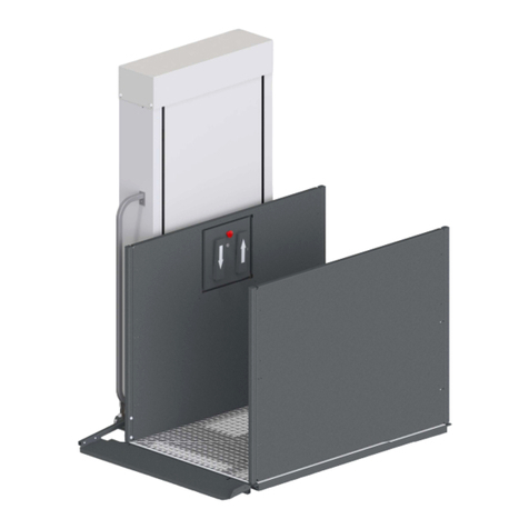
RAM Trus-T-Lift Owner's manual

0
TRUS-T-LIFT
SUPPLEMENTAL
MANUAL #2
LANDING DEVICES

RAM Elevators + Lifts 1-800-563-4382
1

1-800-563-4382 RAM Elevators + Lifts
2
Contents
Section 1: Introduction ...............................................................................................................................1
Section 2: Safety Information ...................................................................................................................1
2.1: Symbols and Definitions .................................................................................................................1
2.2: Additional Symbols .........................................................................................................................1
2.3: Safety Notes.....................................................................................................................................2
Section 3: Upper Landing Gate.................................................................................................................3
Section 4: Landing Door............................................................................................................................5
Section 5: Remote Call Station................................................................................................................. 5
Section 6: Interlock ....................................................................................................................................6

RAM Elevators + Lifts 1-800-563-4382
1
Section 1: Introduction
This supplemental manual has been provided to walk you through the safe and efficient
installation of Trus-T-Lift Landing Devices. Please read this manual, as well as the main
installation manual, thoroughly before installing and operating your lift. We recommend your
lift and any add-ons be installed and serviced by a qualified technician.
Section 2: Safety Information
2.1: Symbols and Definitions
The following notations will be used through this manual to indicate areas that may present
special risks or consideration.
DANGER
Danger messages indicate an imminently hazardous situation, which, if not avoided, could
result in serious injury or even death.
Caution!
Caution messages indicate a potentially hazardous situation which, if not avoided, could
result in serious injury, death, or damage to equipment.
Note
Note messages provide information, such as reminders, general information or additional
guidelines that may provide guidance to the installer.
2.2: Additional Symbols
The following are additional symbols and conventions used through the manual:
A Detail callout, used to call attention
to a detailed mentioned in the body
of the instructions.
Step Callout, labels which step
the given diagram relates to
A
1

1-800-563-4382 RAM Elevators + Lifts
2
2.3: Safety Notes
Caution!
Read all instructions thoroughly before installation or use of this lift. Failure to follow the
instructions in this manual and the associated manuals for testing and operation could
result in serious injury or death. In addition, it will render RAM’s warranty null and void.
Do not connect or disconnect wiring while equipment power is on. Before servicing,
disconnect all power to the equipment. Failure to do so could result in significant injury or
even death.
System may start unexpectedly upon application of power. Unpredictable equipment
movement may result in serious injury or death. Use caution when applying power to the
unit during the installation process.
RAM Elevators + Lifts Inc. (RAM) disclaims any and all liability for any personal injury or
property damage resulting from the operation of a product that has been modified from the
original design. No person or company is authorized to change the design of the product
without written authorization by RAM.
Do not use an improper voltage source or a power source that provides poor quality power.
This may present a significant FIRE HAZARD and/or permanent damage to the equipment.
Do not override any of the safety devices provided with the lift. Doing so will likely lead to
serious injury or even death.
Ensure that there is nothing obstructing the carriage travel before operating the lift.
Ensure there is a minimum of 2in (50mm) and a maximum of 3in (75mm) clearance between
any part or edge of the carriage that could possibly be used as a supporting handhold and
any part of the fixed installation to prevent the trapping of a hand during the travel of the
carriage. See RAM installation drawings for details.
The lift is intended for use by people and not to be used for cargo or other purposes. Lifting
capacity is up to a maximum of 750 lb. unless otherwise noted on the lift and in RAM’s
supplied documentation. (DO NOT OVERLOAD THE LIFT). Overloading the lift will render
RAM’s warranty null and void.
This list of warnings may not be exhaustive, due care around equipment
should be observed

RAM Elevators + Lifts 1-800-563-4382
3
Section 3: Upper Landing Gate
A. Upper Landing Gate
Frame
B. Spring Hinge
C. 4”x4” Angle
D. Interlock & Bracket
E. Door Panel
A
B
C
D
E

1-800-563-4382 RAM Elevators + Lifts
4
Materials
Tools Components
Name #
Name #
Combination Screwdriver 1
Lift Assembly 1
Wire Strippers 1
Landing Gate & Interlock 1
Electric Hand Drill
o With bit and tap specifically
for your preferred fasteners
1
Nylon Tie Straps 1
Preferred Wire Terminators 7
Instructions
Note that these steps are to be carried out before moving the lift into position (Section 4.7 in
the main manual).
Note
These procedures are not the only method for installing an upper landing gate, just the
recommended procedure from RAM.
1) Mount the gate to your landing using one of two ways:
a. Drill through the 4”x4” angle on the bottom of the door
frame and use screws or lag bolts as shown in the
diagram on the right, or
b. Use a Polyurethane Adhesive to mount the threshold to
the upper landing.
2) Mount the Upper Gate Posts to the existing structure in one of
two ways:
a. Drill and tap four holes into the posts (two on each side), and use the provided gate
mounting flanges as shown in the left image, or
b. Use the Polyurethane Adhesive in conjunction with clamps to hold in place as
shown in the right image.
2a 2b
1a

RAM Elevators + Lifts 1-800-563-4382
5
DANGER
Ensure that before carrying out the next step, the lift has been disconnected from power.
Not doing so can damage the unit, and lead to injury and/or death.
3) Wire the gate’s interlock into the tower as per the provided electrical schematics and
wiring diagrams, using protective electrical conduit as per the applicable electrical codes.
Section 4: Landing Door
The installation of a Landing Door is very similar to the installation of a gate, just taller. Follow
the previous procedure to install a landing door, taking into consideration the greater height of
a landing door.
DANGER
Ensure that the lift has been disconnected from power before installing the following
components. Not doing so can damage the unit, and lead to injury and/or death.
Section 5: Remote Call Station
A Trus-T-Lift Remote Call Station can be used to call the carriage
to the landing, or also send the carriage to an alternate landing
when using a remote call/send. Each can be ordered with a
optional key switch to control use.
To install a call station, simply mount it in a suitable location, and
wire it into the lift’s top junction box as per the provided
electrical schematics and wiring diagrams, using protective
conduit as per the applicable electrical code requirements.
Note
If you have a call station with
a key switch, the lift will
not operate unless the key is in the on position
(horizontal).

1-800-563-4382 RAM Elevators + Lifts
6
Section 6: Interlock
Interlocks serve to keep landing doors and gates closed when the lift is not at that landing.
To install the interlock first locate the interlock & bracket on the door jamb as shown in view
#2. With the door closed position near the top of the door jamb with the actuator tab &
bracket inserted in the lock to determine the approximate position of lock and tab. Secure the
interlock bracket to the jamb and the tab bracket to the door using the wood screws provided.
Note that the interlock and actuator tab mounting brackets are slotted allowing for full three
axis adjustment.
Once the interlock and the interlock tab have been mounted, wire the interlock into the lift as
per the provided electrical schematics and wire diagrams using protective conduit as per the
applicable electrical codes.
Other manuals for Trus-T-Lift
4
Table of contents
Other RAM Lifting System manuals
Popular Lifting System manuals by other brands

Terex
Terex SmartPTO quick start guide

Ravaglioli
Ravaglioli RAV1110K instructions

AmeriGlide
AmeriGlide RAVE Installation service

Bohle
Bohle Liftmaster B1 operating instructions

Performance Tool
Performance Tool W1642 owner's manual

AussieCarHoists
AussieCarHoists High-Lift Equipment YL-350W Installation and operation manual

Bend-Pak
Bend-Pak HD-7PBX Installation and operation manual

Bend-Pak
Bend-Pak PL-14000 Installation and operation manual

VOGELS
VOGELS RISE A151 manual

PRO LIFTS
PRO LIFTS VMB TL-A500 Operating instructions & user manual

ARJO HUNTLEIGH
ARJO HUNTLEIGH Minstrel Instructions for use

Bend-Pak
Bend-Pak LR-60P Installation and operation manual