RAM Trus-T-Lift User manual

RESIDENTIAL
TRUS-T-LIFTT M
INSTALLATION MANUAL

RAM Elevators + Lifts 1-800-563-4382
This page is left intentionally blank.

1-800-563-4382 RAM Elevators + Lifts
Contents
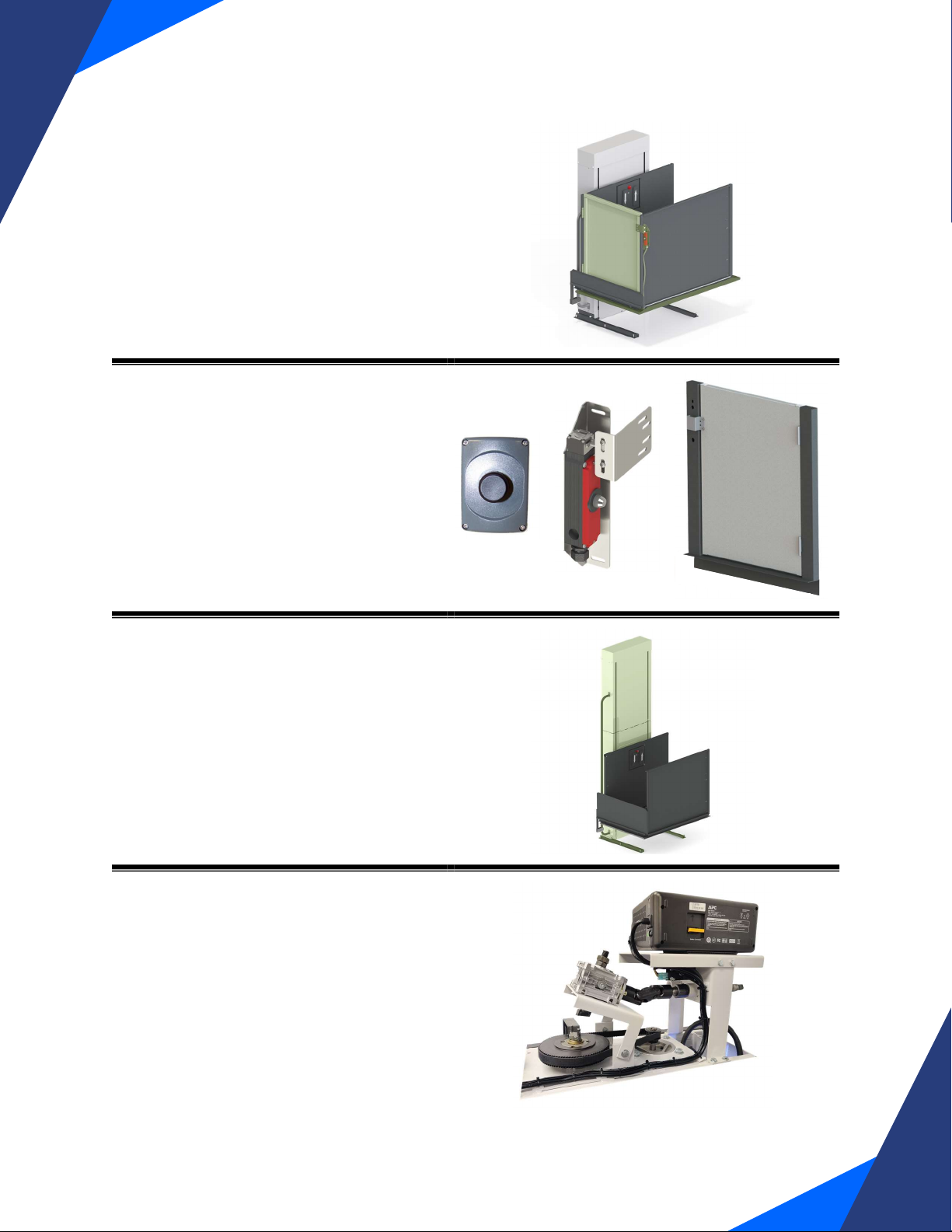
Lift Diagrams ...............................................................................................................................................................2
Section 1: Introduction ................................................................................................................................................4
1.1: Online Resources ............................................................................................................................................................4
1.2: Installer Contact Information......................................................................................................................................4
Section 2: Safety Information....................................................................................................................................5
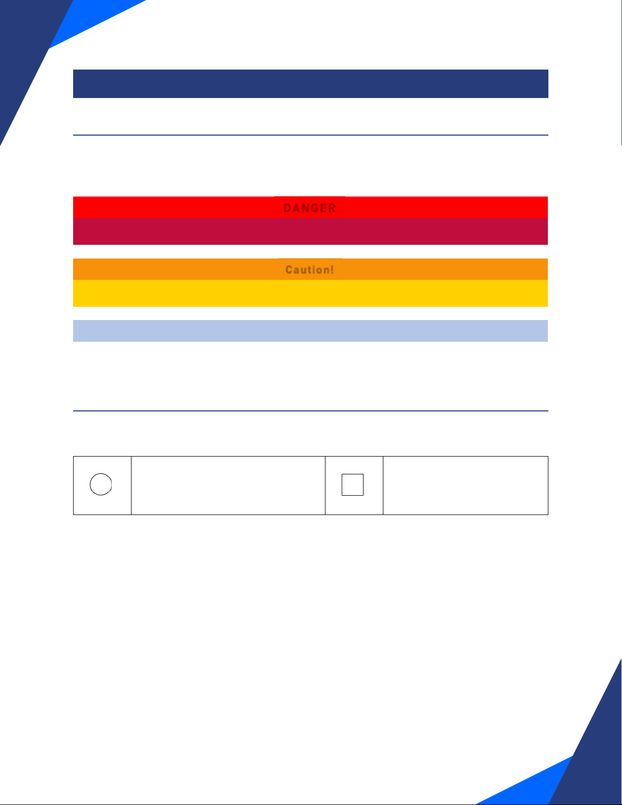
2.1: Safety Symbols and Definitions .................................................................................................................................5
2.2: Additional Symbols........................................................................................................................................................5
2.3: Safety Notes ....................................................................................................................................................................6
Section 3: Pre-Installation.........................................................................................................................................7
3.1: Tools....................................................................................................................................................................................7
3.2: Table of Provided Fasteners ......................................................................................................................................8
3.3: Site Preparation .............................................................................................................................................................9
3.4: Unpacking....................................................................................................................................................................... 10
Section 4: Installation...............................................................................................................................................12
4.1: Base Frame .................................................................................................................................................................... 12
4.2: Locating Lift Keys ........................................................................................................................................................ 13
4.3: Platform.......................................................................................................................................................................... 14
4.4: Plug in and Test Operation ....................................................................................................................................... 16
4.5: Toe Plate......................................................................................................................................................................... 17
4.6: Platform Walls ............................................................................................................................................................. 20
4.7: Final Positioning & Leveling..................................................................................................................................... 21
4.8: Platform Tilt...................................................................................................................................................................22
4.9: Setting the Upper Limit Bracket .............................................................................................................................23
4.10: Anchoring .....................................................................................................................................................................25
4.11: Installing Additional Components..........................................................................................................................25
Section 5: Testing......................................................................................................................................................26
5.1: Full Load Testing...........................................................................................................................................................26
5.2: Upper Limit and Upper Final Limit Switch...........................................................................................................26
5.4: Lower Limit Switch .....................................................................................................................................................27
5.5: Additional Testing Notes............................................................................................................................................27
5.6: Reinstalling the Front Cover ................................................................................................................................... 28
Section 6: Troubleshooting ......................................................................................................................................29

RAM Elevators + Lifts 1-800-563-4382
1
- For additional instructions on
installing a Carriage Gate or
Safety Pan, please see
“Trus-
T-Lift Supplemental Manual
#1 – Carriage Gate and Safety
Pan”.
- For additional instructions for
installing landing devices
such as an interlock or an
upper landing gate, please
see
“Trus-T-Lift
Supplemental Manual #2 –
Landing Devices”.
- For additional instructions for
installing a Tall Tower Trus-
T-Lift (<52” travel height),
please see
“Trus-T-Lift
Supplemental Manual #3 –
Tall Tower”.
- For additional instructions for
installing emergency
operation devices such as a
UPS or a Tower of Power,
please see
“Trus-T-Lift
Supplemental Manual #4 –
Emergency Operation
Devices”.

1-800-563-4382 RAM Elevators + Lifts
2
Lift Diagrams
C
A.
Top Cover
B. Grab Rail
C. Toe Plate Rocker Arm
D. Toe Plate
E. Front Cover
F. Control Wall
G. Control Box
H. Handrail Wall
A
B
D
E
F
G
H

RAM Elevators + Lifts 1-800-563-4382
3
A.
Lift Motor
B. Drive Screw
C. Guide Rail Tube
D. Upper Limit Bracket
E. Guide Frame
F. Upper Limit Switch
G. Lower Limit Switch
B
E
D
F
A
G
C

1-800-563-4382 RAM Elevators + Lifts
4
Section 1: Introduction
Thank you for selecting the Trus-T-Lift™. When operated properly, the Trus-T-Lift™ is designed
to provide years of trouble-free service. This manual is provided to walk you through
installation safely and efficiently. Please read this manual thoroughly before installing and
operating your lift for the first time. We recommend your lift be installed and serviced by a
qualified technician.
1.1: Online Resources
Additional resources for install such as product updates and installation videos, are available
online on our website trustram.com.
1.2: Installer Contact Information
Affiliated Company:
Phone Number:
Street Address:

RAM Elevators + Lifts 1-800-563-4382
5
Section 2: Safety Information
2.1: Safety Symbols and Definitions
The following notations will be used through this manual to indicate areas that may present
special risks or consideration.
DANGER
Danger messages indicate an imminently hazardous situation, which, if not avoided, could
result in serious injury or even death.
Caution!
Caution messages indicate a potentially hazardous situation which, if not avoided, could
result in serious injury, death, or damage to equipment.
Note
Note messages provide information, such as reminders, general information or additional
guidelines that may provide guidance to the installer.
2.2: Additional Symbols
The following are additional symbols and conventions used through the manual:
A Detail callout, used to call attention
to a detailed mentioned in the body
of the instructions.
Step Callout, labels which step
the given diagram relates to
A
1

1-800-563-4382 RAM Elevators + Lifts
6
2.3: Safety Notes
Caution!
Read all instructions thoroughly before installation or use of this lift. Failure to follow the
instructions in this manual and the associated manuals for testing and operation could
result in serious injury or death. In addition, it will render RAM’s warranty null and void.
Do not connect or disconnect wiring while equipment power is on. Before servicing,
disconnect all power to the equipment. Failure to do so could result in significant injury or
even death.
System may start unexpectedly upon application of power. Unpredictable equipment
movement may result in serious injury or death. Use caution when applying power to the
unit during the installation process.
RAM Elevators + Lifts Inc. (RAM) disclaims any and all liability for any personal injury or
property damage resulting from the operation of a product that has been modified from the
original design. No person or company is authorized to change the design of the product
without written authorization by RAM.
Do not use an improper voltage source or a power source that provides poor quality power.
This may present a significant FIRE HAZARD and/or permanent damage to the equipment.
Do not override any of the safety devices provided with the lift. Doing so will likely lead to
serious injury or even death.
Ensure that there is nothing obstructing the carriage travel before operating the lift.
Ensure there is a minimum of 2in (50mm) and a maximum of 3in (75mm) clearance between
any part or edge of the carriage that could possibly be used as a supporting handhold and
any part of the fixed installation to prevent the trapping of a hand during the travel of the
carriage. See RAM installation drawings for details.
The lift is intended for use by people and not to be used for cargo or other purposes. Lifting
capacity is up to a maximum of 750 lb. unless otherwise noted on the lift and in RAM’s
supplied documentation. (DO NOT OVERLOAD THE LIFT). Overloading the lift will render
RAM’s warranty null and void.
This list of warnings may not be exhaustive, due care around equipment
should be observed.

RAM Elevators + Lifts 1-800-563-4382
7
Section 3: Pre-Installation
3.1: Tools
The following is the list of tools that must be provided by the installer to complete the
installation.
Tools Sockets
Claw Hammer 7/16”
3/8” Socket Ratchet 1/2"
6” Socket Ratchet Extension 9/16”
12” Socket Ratchet Extension 3/4"
Side Cutters
Combination Screwdriver
o #2 Phillips and #2 Robertson
Bits
Combination Wrenches
3/8”
Large Flathead Screwdriver 7/16”
Utility Knife 1/2"
Concrete Drill with 3/8” Bit 9/16”
Tape Measure 3/4"
Manual Crank Components (These come with your lift)
3/8” Socket ratchet 15/16” Socket
Note
Keep the manual crank components in a safe place near the lift, as in the event of an emergency, you
may need them to manually lift or lower the platform.

1-800-563-4382 RAM Elevators + Lifts
8
3.2: Table of Provided Fasteners
Concrete Anchor
2-3/4” Long
Galvanised Steel
(1 : 1.5 Scale)
Front Cover Screw
Phillips Head, 10-32
Thread
1/2" Long
Stainless Steel
Platform
Mounting Bolt
1/2" Bolt
1-1/2” Long
Bronze-Coloured
Top Cover Screw
Phillips Head, 10-32
Thread
1” Long
Stainless Steel
Leveling & Toe
Plate Mounting Bolt
3/8” Bolt
1-1/4” Long
Galvanised Steel
Toe Plate Screw
Flathead/Robertson
Head (10-32
Thread)
5/8” Long
Galvanised Steel
Leg Mounting Bolt
(with washers)
1/2" Bolt
1-1/4" Long
Galvanised Steel
Toe Plate Washer
3/16” ID, 1/2" OD
Galvanised Steel
Wall Mounting Bolt
1/4" Bolt
3/4" Long
Galvanised Steel
Large Plastic
Washer
3/16” ID, 9/16” OD
White Plastic
Wall Mounting
Washers
1/4" ID, 5/8” OD
Galvanised Steel
Small Plastic
Washer
3/16” ID, 7/16” OD
White Plastic
All figures to scale unless otherwise noted.

RAM Elevators + Lifts 1-800-563-4382
9
3.3: Site Preparation
When preparing to install a Trus-T-Lift, there are a few things that you should consider.
The support base for the Trus-T-Lift must be solid and capable of anchoring and supporting
the base frame. We recommend a 60 by 60-inch concrete pad approximately 4 inches thick.
The pad should be level within a 1/2 inch and smooth with no projections.
The travel distance of a Trus-T-lift is measured
from the support base to the upper landing sill. Trus-T-
Lift is available in 7 different maximum lifting heights
from 28” to 14ft. Each tower can travel a maximum
distance indicated by the model number. The model
shown in this manual is a 52” tower and can be easily set
to automatically stop at any point up to a maximum of 52
inches lifting height.
The travel wall is a barrier that extends from the
upper landing sill to the support base and helps to keep
the user secure on the platform while operating the lift. This wall must be plumb, smooth, and
solid with no projections.
Another consideration is the power source for the lift. Make sure there is a standard
15A/110VAC outlet within 6 feet of the tower location.
DANGER
If the travel wall is not prepared in compliance with the above statement, possible crushing or
shearing hazards may be present and this will likely cause serious injury or harm.
The Trus-T-Lift is available in two different platform configurations, straight through
and 90-degree access. The straight through model has its entrance and exit on either side of
the lift, while the 90-degree access allows the user to exit 90-degrees opposite the tower on
the upper level. Note that the lower entrance side with the toeplate ramp can be changed from
the left or right side of the tower.
Straight Through
90-Degree Access
ELECTRICAL
OUTLET
SUPPORT BASE

1-800-563-4382 RAM Elevators + Lifts
10
3.4: Unpacking
Materials
Tools Components
Name #
Name #
Claw Hammer 1
Packaged Lift 1
Utility Knife 1
3/8” Socket Ratchet 1
3/4" Socket 1
3/4" Combination Wrench 1
Instructions
Note
When you receive your Trus-T-lift, be sure to carefully inspect the packaging for any damage. Note
any potential damage on the waybill from the shipper and take photos.
1) Remove the outer layers of packaging, careful to not damage any components
underneath.
2) Retrieve the plastic bag on the front of the unit containing the
following:
a. Fastener parts bag
b. Manual crank ratchet and socket
c. An envelope containing the following:
i. the installation manual,
ii. electrical diagrams,
iii. the owner’s manual, and
iv. any supplementary installation documents.

RAM Elevators + Lifts 1-800-563-4382
11
Caution!
Take care to not
damage the protective
powder coating on the
components, as
unprotected metal can
corrode causing the
paint to lift and separate
from the metal.
3) Carefully remove
the foam
wrapping the lift
and the
components. Set
these aside each
component. After
all the foam is
removed, you will be left with the lift tower bolted to the pallet.
Note
The packing foam your lift is wrapped in can also be used to cushion
components against a wall of the floor, to prevent damage to them and the
components.
4) Remove the section of the pallet shown in the below figure,
then remove the bolts fastening the tower to the pallet using
the 3/4" socket and combination wrench.
Caution!
Use best lifting practises when moving the lift. Not doing so can lead to serious injury.
5) Carefully move the lift off of the pallet, and put it near its final location.
Manual Crank Bag
Fastener Bag Installation Manual
Owner’s Manual
Electrical Diagrams

1-800-563-4382 RAM Elevators + Lifts
12
Section 4: Installation
4.1: Base Frame
Materials:
Tools Components
Name #
Name #
3/8” Socket Ratchet 1
Base Legs 2
3/4” Socket 1
Tower 1
Instructions
1) Retract each leveling bolt (3/8” Bolt) ( A ) so
the legs will sit completely flat on the floor,
with no support from the bolts.
2) Remove each mounting bolt (1/2” Bolt) with its
washers ( B ) and slide the legs into place.
3) Reinstall the mounting bolts.
4) Repeat for the other base leg.
A
B

RAM Elevators + Lifts 1-800-563-4382
13
4.2: Locating Lift Keys
Materials
Tools Components
Name #
Name #
Side Cutters 1
Tower and Base Leg Assembly (4.1) 1
Instructions
1) On the front of the tower, you will find the power cord
zip-tied to the guide frame. Cut this tie.
2) Locate the control box key zip tied to the end of the
power cord. Cut the tie and retrieve the key.
3) Insert the control box key retrieved in the last step into
the keyhole on the right of the control box and apply a
small amount of pressure on the lid as you turn the key
to open the box.
4) Retrieve the on-off keys zip tied to the inside of the
front of the control box, and close and lock the box.
5) Put the on-off key into the center key slot on the front
of the control box and turn it to the right.
Control Box Cover
Key
On/Off Control
Key

1-800-563-4382 RAM Elevators + Lifts
14
4.3: Platform
Materials
Tools Components
Name #
Name #
Phillips Head Screwdriver 1
Tower and Base Leg Assembly (4.1) 1
3/8” Socket Ratchet 1
Platform 1
15/16” Socket 1
Platform Mounting Bolts (1/2” Bolt) 2
3/4" Socket 1
Instructions
1) Use the Phillips head screwdriver to loosen the screws holding the top cover ( 1 ). Note
that they do not need to be removed, only loosened. Remove the top cover.
Note
The front panel of the tower is fastened with both screws and snap-together pads, so it may take a
small amount of pressure to remove once the screws have been removed.
2) Remove the front cover screws ( 2 ) using the Phillips head screwdriver and remove
the front panel ( 3 ).
3) Carefully slide the platform onto the base legs until it lines up with the guide frame.

RAM Elevators + Lifts 1-800-563-4382
15
4) Use the manual crank wrench and 15/16” socket to lower or raise the guide frame until
the bolt holes line up with the holes on the platform.
Caution!
Over-tightening the bolts in the next step can compromise the operation of the lift, so make sure they
are only tightened the specified amount
5) Fasten the platform to the guide frame using the Platform mounting bolts (1/2” bolts)
and the 3/4" socket. Ensure you do not over tighten these (only until one or two threads
are visible on the other side of the nut)

1-800-563-4382 RAM Elevators + Lifts
16
4.4: Plug in and Test Operation
Materials
Tools Components
Name #
Name #
Lift Assembly (4.3) 1
Instructions
1) Slide the top cover back onto the unit, until you hear the top cover switch activate. Note
that the smaller plastic washer goes inside the cover, and the larger washer on the
outside.
Note
You don’t need to re-tighten the screws on the top cover, as you will be
removing it again later in the installation.
Double check that the emergency stop button is not depressed before
carrying out the next steps, and the on/off key is in and turned clockwise.
2) Plug the lift into the wall (standard 110V 15A outlet)
DANGER
The rotating screw will be exposed when running the machine without the front cover. Keep hair,
loose clothing, or anything that could get caught in the screw away from the machine.
3) Test the lift’s operation by pressing the up and down paddles.
Click
Down Up
Emergency Stop

RAM Elevators + Lifts 1-800-563-4382
17
4.5: Toe Plate
Materials
Tools Components
Name #
Name #
3/8” Socket Ratchet 1
Lift Assembly (4.4) 1
9/16” Socket 1
Toe Plate 1
6” Extension 1
Toe Plate Mounting Bolt (3/8” Bolts) 2
Flathead Screwdriver 1
Utility Knife 1
Instructions
Note
On some units, the toe plate will come pre-installed. If your unit already has its toe plate connected to
the platform, skip to step 4.
Caution!
For power wheelchairs that can exert loads higher than 125 lb of force, a toe plate is insufficient
safety protection, and a carriage gate option would also be required.
1) Raise the platform to a good working height (about 2-3 ft off the ground)
2) Line the holes in the toe plate with the holes on the platform and flip the plate up. The
side these holes are on will change depending on what orientation you ordered your lift
in.
Note
In the next step, do not over-tighten the bolts, as the toe plate will not be able to operate correctly.
Other manuals for Trus-T-Lift
4
Table of contents
Other RAM Lifting System manuals
Popular Lifting System manuals by other brands

Bruno
Bruno JOEY VSL-4400G Operator's manual

Challenger Lifts
Challenger Lifts Versymmetric Installation, operation & maintenance manual

BlitzRotary
BlitzRotary Master Gear 1 operating instructions

Conquip
Conquip Goods Cage user guide

Harmar Mobility
Harmar Mobility Pinnacle SL600 Installation & service manual

Genie
Genie S-100 Service manual

RUTHMANN
RUTHMANN Steiger TB270 Operating and maintenance instructions

JLG
JLG 25AM Operation and safety manual

Palfinger
Palfinger MiniFix owner's manual

Skyjack
Skyjack SJ12 E Service manual

SCANCLIMBER
SCANCLIMBER SC500K instruction manual

PFlow Industries
PFlow Industries B Series Owner's, Installation and Maintenance Manual