R&S NRP Series User manual

R&S®NRP Series
Power Sensors
Getting Started
1419017002
Version 16
(>C1Ô2)

This manual gives an introduction to the R&S®NRP series power sensors:
●R&S®NRPxxA(N) average power sensors
●R&S®NRPxxS(N) three-path diode power sensors
●R&S®NRP18S-xx high-power three-path diode power sensors
●R&S®NRPxxT(N) thermal power sensors
●R&S®NRPxxTWG thermal waveguide power sensors
© 2022 Rohde & Schwarz GmbH & Co. KG
Muehldorfstr. 15, 81671 Muenchen, Germany
Phone: +49 89 41 29 - 0
Email: [email protected]
Internet: www.rohde-schwarz.com
Subject to change – data without tolerance limits is not binding.
R&S® is a registered trademark of Rohde & Schwarz GmbH & Co. KG.
Trade names are trademarks of the owners.
1419.0170.02 | Version 16 | R&S®NRP Series
Throughout this manual, products from Rohde & Schwarz are indicated without the ® symbol, for example
R&S®NRX is abbreviated as R&S NRX.

Contents
R&S®NRP Series
3Getting Started 1419.0170.02 ─ 16
Contents
1 Safety and regulatory information....................................... 5
1.1 Safety instructions................................................................................5
1.2 Labels on the product.......................................................................... 6
1.3 Warning messages in the documentation.......................................... 7
2 Welcome................................................................................. 8
2.1 Documentation overview..................................................................... 8
2.1.1 Getting started manual............................................................................8
2.1.2 User manuals..........................................................................................8
2.1.3 Tutorials.................................................................................................. 8
2.1.4 Instrument security procedures...............................................................9
2.1.5 Basic safety instructions......................................................................... 9
2.1.6 Data sheets and brochures.....................................................................9
2.1.7 Release notes and open source acknowledgment (OSA)...................... 9
2.1.8 Application notes, application cards, white papers, etc........................ 10
2.2 Key features........................................................................................ 10
3 Preparing for use................................................................. 11
3.1 Unpacking and checking....................................................................11
3.2 Choosing the operating site...............................................................11
3.3 Considerations for test setup............................................................ 12
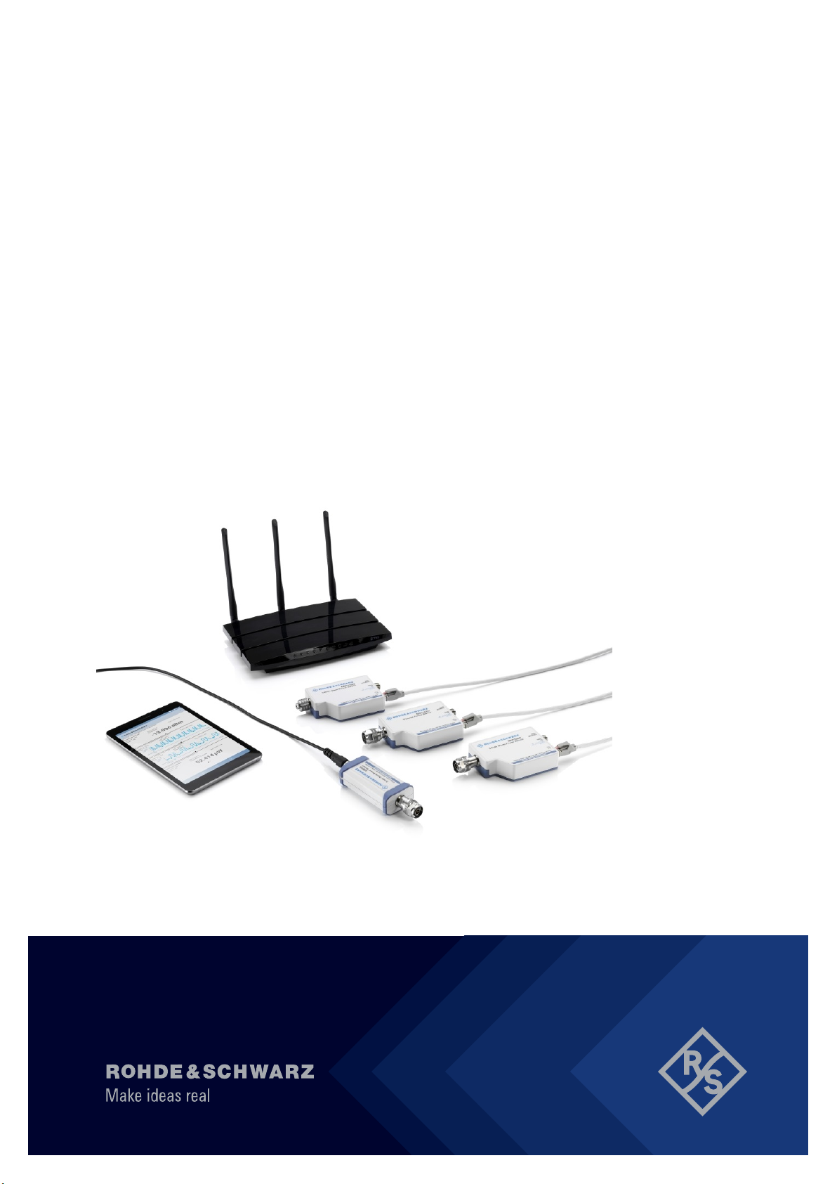
3.4 Connecting to a DUT.......................................................................... 13
3.5 Powering the power sensor............................................................... 14
3.6 Connecting a cable to the host interface..........................................15
3.7 Connecting to a controlling host.......................................................16
3.7.1 Computer.............................................................................................. 16
3.7.2 Base unit............................................................................................... 19

Contents
R&S®NRP Series
4Getting Started 1419.0170.02 ─ 16
3.7.3 Using a LAN connection....................................................................... 20
4 Power sensor tour............................................................... 27
4.1 RF connector.......................................................................................28
4.2 Status information.............................................................................. 30
4.3 Host interface...................................................................................... 30
4.4 Trigger I/O connector..........................................................................30
4.5 LAN PoE interface...............................................................................31
5 Operating concepts............................................................. 32
5.1 R&S NRP Toolkit................................................................................. 32
5.1.1 Versions and downloads....................................................................... 32
5.1.2 System requirements............................................................................ 33
5.1.3 R&S NRP Toolkit for Windows.............................................................. 33
5.2 Browser-based user interface........................................................... 35
5.3 Remote control....................................................................................37
5.4 R&S NRPV........................................................................................... 37
5.5 R&S Power Viewer.............................................................................. 39
5.6 R&S Power Viewer Mobile..................................................................41
5.7 R&S NRX..............................................................................................41
6 Remote control interfaces and protocols..........................44
6.1 USB interface...................................................................................... 44
6.2 Ethernet interface............................................................................... 47
6.2.1 VISA resource strings........................................................................... 47
7 Contacting customer support............................................ 50
Index..................................................................................... 51

Safety and regulatory information
R&S®NRP Series
5Getting Started 1419.0170.02 ─ 16
1 Safety and regulatory information
The product documentation helps you use the product safely and efficiently. Fol-
low the instructions provided here and in the following chapters.
Intended use
The power sensors are intended for accurate and uncomplicated power measure-
ments in production, R&D and calibration labs as well as for installation and main-
tenance tasks. The supported base units are listed in the data sheet. Observe the
operating conditions and performance limits stated in the data sheet.
Target audience
The target audience is developers and technicians. The required skills and expe-
rience in power measurements depend on the used operating concept.
The power sensors are suitable for numerous power measurement applications.
Their application depends on the power sensor type and the frequency range of
the power sensor. For details, see the user manual or the data sheet.
Where do I find safety information?
Safety information is part of the product documentation. It warns you of potential
dangers and gives instructions on how to prevent personal injury or damage
caused by dangerous situations. Safety information is provided as follows:
●In Chapter 1.1, "Safety instructions", on page 5. The same information is
provided in many languages as printed "Safety Instructions". The printed
"Safety Instructions" are delivered with the product.
●Throughout the documentation, safety instructions are provided when you
need to take care during setup or operation.
1.1 Safety instructions
Products from the Rohde & Schwarz group of companies are manufactured
according to the highest technical standards. To use the products safely, follow
the instructions provided here and in the product documentation. Keep the prod-
uct documentation nearby and offer it to other users.
Safety instructions

Safety and regulatory information
R&S®NRP Series
6Getting Started 1419.0170.02 ─ 16
Use the product only for its intended use and within its performance limits. Inten-
ded use and limits are described in the product documentation such as the data
sheet, manuals and the printed "Safety Instructions". If you are unsure about the
appropriate use, contact Rohde & Schwarz customer service.
Using the product requires specialists or specially trained personnel. These users
also need sound knowledge of at least one of the languages in which the user
interfaces and the product documentation are available.
Never open the casing of the product. Only service personnel authorized by
Rohde & Schwarz are allowed to repair the product. If any part of the product is
damaged or broken, stop using the product. Contact Rohde & Schwarz customer
service at http://www.customersupport.rohde-schwarz.com.
Choosing the operating site
Only use the product indoors. The product casing is not waterproof.
Observe the ambient conditions such as altitude, operating temperature and cli-
matic loads; see the data sheet.
Meaning of safety labels
Safety labels on the product warn against potential hazards.
Potential hazard
Read the product documentation to avoid personal injury or product damage.
Electrical hazard
Indicates live parts. Risk of electric shock, fire, personal injury or even death.
1.2 Labels on the product
Labels on the product inform about:
●Personal safety
See "Meaning of safety labels" on page 6.
●Environment safety
See Table 1-1.
●Identification of the product
See "Default hostname" on page 24.
Labels on the product

Safety and regulatory information
R&S®NRP Series
7Getting Started 1419.0170.02 ─ 16
Table 1-1: Labels regarding environment safety
Labeling in line with EN 50419 for disposal of electrical and electronic equipment after
the product has come to the end of its service life.
For more information, see the user manual.
1.3 Warning messages in the documentation
A warning message points out a risk or danger that you need to be aware of. The
signal word indicates the severity of the safety hazard and how likely it will occur
if you do not follow the safety precautions.
NOTICE
Potential risks of damage. Could result in damage to the supported product or to
other property.
Warning messages in the documentation

Welcome
R&S®NRP Series
8Getting Started 1419.0170.02 ─ 16
2 Welcome
This chapter provides an overview of the user documentation and an introduction
to the R&S NRP series power sensor.
2.1 Documentation overview
This section provides an overview of the R&S NRP series power sensor user doc-
umentation. Unless specified otherwise, you find the documents on the R&S NRP
series power sensor product page at:
www.rohde-schwarz.com/product/nrp-a-an
www.rohde-schwarz.com/product/nrp_s_sn
www.rohde-schwarz.com/product/nrp18s-xx
www.rohde-schwarz.com/product/nrp-t-tn
2.1.1 Getting started manual
Introduces the R&S NRP series power sensor and describes how to set up and
start working with the product. Includes basic operations and general information,
e.g. safety instructions, etc. A printed version is delivered with the power sensor.
2.1.2 User manuals
Contains the description of all instrument modes and functions. It also provides
an introduction to remote control, a complete description of the remote control
commands with programming examples, and information on maintenance and
interfaces. Includes the contents of the getting started manual.
2.1.3 Tutorials
Tutorials offer guided examples and demonstrations on operating the R&S NRP
series power sensor. They are provided on the product page of the internet.
Documentation overview

Welcome
R&S®NRP Series
9Getting Started 1419.0170.02 ─ 16
2.1.4 Instrument security procedures
Deals with security issues when working with the R&S NRP series power sensor
in secure areas. It is available for download on the Internet.
2.1.5 Basic safety instructions
Contains safety instructions, operating conditions and further important informa-
tion. The printed document is delivered with the instrument.
2.1.6 Data sheets and brochures
The data sheet contains the technical specifications of the R&S NRP series
power sensor. It also lists the firmware applications and their order numbers, and
optional accessories.
The brochure provides an overview of the instrument and deals with the specific
characteristics.
www.rohde-schwarz.com/brochure-datasheet/nrp-a-an
www.rohde-schwarz.com/brochure-datasheet/nrp_s_sn
www.rohde-schwarz.com/brochure-datasheet/nrp18s-xx
www.rohde-schwarz.com/brochure-datasheet/nrp-t-tn
2.1.7 Release notes and open source acknowledgment (OSA)
The release notes list new features, improvements and known issues of the cur-
rent firmware version, and describe the firmware installation.
The "Open Source Acknowledgment" is provided on the user documentation CD-
ROM, included in the delivery. It contains verbatim license texts of the used open
source software.
www.rohde-schwarz.com/firmware/nrp-a-an
www.rohde-schwarz.com/firmware/nrp_s_sn
www.rohde-schwarz.com/firmware/nrp-t-tn
Documentation overview

Welcome
R&S®NRP Series
10Getting Started 1419.0170.02 ─ 16
2.1.8 Application notes, application cards, white papers, etc.
These documents deal with special applications or background information on
particular topics.
www.rohde-schwarz.com/application/nrp_s_sn
www.rohde-schwarz.com/application/nrp18s-xx
2.2 Key features
The R&S NRP series power sensors are the successors of the established
R&S NRP‑Z series of RF power sensors.
They provide a high-speed USB interface that constitutes both the communication
port and the power supply connection.
Also, most power sensors are available with an additional Gigabit Ethernet inter-
face with Power-over-Ethernet (PoE) power supply. The power sensors with net-
working capabilities, the R&S NRP LAN power sensors, are marked with a trailing
N in their names:
●R&S NRPxxSN
●R&S NRPxxAN
●R&S NRPxxTN
The R&S NRP series power sensors are compatible with the R&S NRP‑Z power
sensors in both the interface (USB) and a common command subset. This com-
patibility makes the replacement of the old power sensors easy.
For a detailed specification, refer to the data sheet and the brochure.
Key features

Preparing for use
R&S®NRP Series
11Getting Started 1419.0170.02 ─ 16
3 Preparing for use
Here, you can find basic information about setting up the product for the first time.
●Unpacking and checking................................................................................. 11
●Choosing the operating site.............................................................................11
●Considerations for test setup.......................................................................... 12
●Connecting to a DUT.......................................................................................13
●Powering the power sensor.............................................................................14
●Connecting a cable to the host interface.........................................................15
●Connecting to a controlling host......................................................................16
3.1 Unpacking and checking
1. Unpack the product carefully.
2. Retain the original packing material. Use it when transporting or shipping the
product later.
3. Using the delivery notes, check the equipment for completeness.
4. Check the equipment for damage.
If the delivery is incomplete or equipment is damaged, contact
Rohde & Schwarz.
3.2 Choosing the operating site
Specific operating conditions ensure proper operation and avoid damage to the
product and connected devices. For information on environmental conditions
such as ambient temperature and humidity, see the data sheet.
Electromagnetic compatibility classes
The electromagnetic compatibility (EMC) class indicates where you can operate
the product. The EMC class of the product is given in the data sheet.
●Class B equipment is suitable for use in:
Choosing the operating site

Preparing for use
R&S®NRP Series
12Getting Started 1419.0170.02 ─ 16
– Residential environments
– Environments that are directly connected to a low-voltage supply network
that supplies residential buildings
●Class A equipment is intended for use in industrial environments. It can cause
radio disturbances in residential environments due to possible conducted and
radiated disturbances. It is therefore not suitable for class B environments.
If class A equipment causes radio disturbances, take appropriate measures to
eliminate them.
3.3 Considerations for test setup
Give particular attention to the following aspects when handling power sensors.
Handling the R&S NRP18S‑xx power sensor
►CAUTION! Hot surfaces. Under certain conditions, the maximum surface tem-
peratures of the power sensor can exceed the limits defined in the
EN 61010-1 standard, safety requirements for electrical equipment for mea-
surement, control and laboratory use.
Provide protection as follows:
a) Ensure that unintentional contact with the power sensor is impossible.
b) Wear heat-protective gloves when touching the power sensor after opera-
tion.
Handling the TVAC‑compliant power sensor
1. NOTICE! Avoid contamination.
Always wear clean protective gloves when handling the TVAC‑compliant
power sensor to protect the power sensor and its environment from contami-
nation.
2. NOTICE! Reduce outgassing to a minimum by following this bake-out proce-
dure.
Vacuum bake the TVAC‑compliant power sensor for 100 hours at 85 °C at a
pressure lower than 10-5 mbar.
EMI impact on measurement results
Electromagnetic interference (EMI) can affect the measurement results.
Considerations for test setup

Preparing for use
R&S®NRP Series
13Getting Started 1419.0170.02 ─ 16
To suppress electromagnetic radiation during operation:
●Use high-quality shielded cables, for example, double-shielded RF and inter-
face cables.
●Always terminate open cable ends.
●Ensure that connected external devices comply with EMC regulations.
Signal input and output levels
Information on signal levels is provided in the data sheet. Keep the signal levels
within the specified ranges to avoid damage to the product and connected devi-
ces.
The following applies only to the R&S NRP18S‑xx power sensors:
The test limits specified on the name plate apply only if the power sensor is oper-
ated together with the RF power attenuator supplied. If the power sensor is oper-
ated without attenuator, the lower test limits of the R&S NRP18S power sensor
apply, as specified in the data sheet.
Preventing electrostatic discharge (ESD)
Electrostatic discharge is most likely to occur when you connect or disconnect a
DUT.
►NOTICE! Electrostatic discharge can damage the electronic components of
the product and the device under test (DUT).
Ground yourself to prevent electrostatic discharge damage:
a) Use a wrist strap and cord to connect yourself to ground.
b) Use a conductive floor mat and heel strap combination.
3.4 Connecting to a DUT
For connecting the power sensor to a DUT, use the RF connector. See Chap-
ter 4.1, "RF connector", on page 28.
To connect to the DUT
1. Ensure that the RF connector of your DUT is compatible with the RF connec-
tor of the power sensor.
Connecting to a DUT

Preparing for use
R&S®NRP Series
14Getting Started 1419.0170.02 ─ 16
2. Inspect both RF connectors carefully. Look for metal particles, contaminants
and defects.
If either RF connector is damaged, do not proceed, because the risk of dam-
aging the mating connector is too high.
3. Insert the RF connector straight into the RF output of your DUT. Take care not
to tilt it.
180
NRP
3-Path Diode Power Sensor
MHz to GHz, 100 pW to 200 mW (−70 dBm to +23 dBm)
SMART SENSOR TECHNOLOGY
4. NOTICE! Risk of damaging the center pin of the RF connector. Only rotate the
hex nut of the RF connector. Never rotate the power sensor itself.
Tighten the RF connector manually.
5. Tighten the RF connector using a torque wrench with the nominal torque rec-
ommended in Chapter 4.1, "RF connector", on page 28 to ensure maximum
measurement accuracy.
To disconnect from the DUT
1. NOTICE! Risk of damaging the center pin of the RF connector. Only rotate the
hex nut of the RF connector. Never rotate the power sensor itself.
Carefully loosen the union nut at the front of the RF connector of the power
sensor.
2. Remove the power sensor.
3.5 Powering the power sensor
The electrical power for the R&S NRP series power sensor is supplied over one
of the following interfaces:
●Host interface
See Chapter 4.3, "Host interface", on page 30.
●LAN PoE interface
Available only for LAN power sensors. See Chapter 4.5, "LAN PoE interface",
on page 31.
Powering the power sensor

Preparing for use
R&S®NRP Series
15Getting Started 1419.0170.02 ─ 16
If you use the Ethernet interface of the LAN power sensors, you have to pro-
vide the electrical power by power over Ethernet (PoE). In this case, you
cannot provide the electrical power over the host interface instead.
Choose the PoE power sourcing equipment (PSE) with care
Only use PoE power sourcing equipment (PSE) as specified in the IEEE stand-
ards 802.3af or IEEE 802.3at. Otherwise, the following can happen:
●If too much power is supplied, the LAN power sensor can get overheated and
become damaged as a result.
●If the supplied power is not sufficient, the LAN power sensor does not work
properly or not at all.
3.6 Connecting a cable to the host interface
For connecting the power sensor to a USB host, use the host interface. See
Chapter 4.3, "Host interface", on page 30.
Depending on the USB host, use one of the following cables:
●Computer or R&S NRP‑Z5 sensor hub:
R&S NRP‑ZKU cable with a USB connector
See Chapter 3.7.1, "Computer", on page 16.
●Base units or other supported Rohde & Schwarz instruments:
R&S NRP‑ZK6 cable with a push-pull type connector
See Chapter 3.7.2, "Base unit", on page 19.
These cables can be obtained in different lengths up to 5 meters. The order num-
bers are provided in the data sheet.
To connect a cable to the host interface of the power sensor
1. Insert the screw-lock cable connector into the host interface connector of the
power sensor.
2. Tighten the union nut manually.
To disconnect the host interface of the power sensor
1. Loosen the union nut of the screw-lock cable connector.
Connecting a cable to the host interface

Preparing for use
R&S®NRP Series
16Getting Started 1419.0170.02 ─ 16
2. Remove the cable.
3.7 Connecting to a controlling host
As a controlling host, you can use:
●Computer
●Base unit
For operating the power sensor, you can choose from various possibilities. For
details, see Chapter 5, "Operating concepts", on page 32.
3.7.1 Computer
If the controlling host is a computer, you can operate the power sensor in several
ways. For details, see Chapter 5, "Operating concepts", on page 32.
► Establish the connection using:
● Host interface
See Chapter 3.7.1.1, "Simple USB connection", on page 16.
See Chapter 3.7.1.2, "R&S NRP‑Z5 sensor hub setup", on page 17.
● LAN interface, if the power sensor is a LAN power sensor
See Chapter 3.7.3, "Using a LAN connection", on page 20.
3.7.1.1 Simple USB connection
All R&S NRP power sensors can be connected to the USB interface of a com-
puter.
Required equipment
●R&S NRP power sensor
●R&S NRP‑ZKU cable
Connecting to a controlling host

Preparing for use
R&S®NRP Series
17Getting Started 1419.0170.02 ─ 16
Setup
NRP
3-Path Diode Power Sensor
MHz to GHz, 100 pW to 200 mW (−70 dBm to +23 dBm)
SMART SENSOR TECHNOLOGY
12
34
5
6
Figure 3-1: Setup with an R&S
NRP
‑
ZKU cable
1 = Signal source
2 = R&S NRP power sensor
3 = Host interface connector
4 = R&S NRP‑ZKU cable
5 = USB connector
6 = Computer with installed VISA driver or R&S NRP Toolkit
Set up as shown in Figure 3-1.
1. Connect the R&S NRP‑ZKU cable to the power sensor. See "To connect a
cable to the host interface of the power sensor" on page 15.
2. Connect the R&S NRP‑ZKU cable to the computer.
3. NOTICE! Incorrectly connecting or disconnecting the power sensor can dam-
age the power sensor or lead to erroneous results. Ensure that you connect or
disconnect the power sensor as described in Chapter 3.4, "Connecting to a
DUT", on page 13.
Connect the power sensor to the signal source.
4. On the computer, start a software application to view the measurement
results. See Chapter 5, "Operating concepts", on page 32.
3.7.1.2 R&S NRP‑Z5 sensor hub setup
The R&S NRP‑Z5 sensor hub (high-speed USB 2.0) can host up to four R&S
NRP power sensors and provides simultaneous external triggering to all connec-
ted sensors.
Required equipment
●1 to 4 R&S NRP power sensors
Connecting to a controlling host

Preparing for use
R&S®NRP Series
18Getting Started 1419.0170.02 ─ 16
●1 R&S NRP‑ZK6 cable per sensor
●R&S NRP‑Z5 sensor hub with external power supply unit and USB cable
●BNC cables to connect the trigger input and trigger output signals (optional)
Setup
1234
8
9
7
65
NRP
3-Path Diode Power Sensor
MHz to GHz, 100 pW to 200 mW (−70 dBm to +23 dBm)
SMART SENSOR TECHNOLOGY
Figure 3-2: Setup with an R&S NRP-Z5 sensor hub
1 = External power supply unit
2 = Connect to AC power supply.
3 = Connect to computer with USB host interface.
4 = Optional: Connect to trigger source.
5 = Optional: Connect to triggered device.
6 = R&S NRP‑Z5 sensor hub
7 = Signal source (DUT)
8 = R&S NRP power sensor
9 = R&S NRP‑ZK6 cable
Set up as shown in Figure 3-2.
1. Connect the R&S NRP‑ZK6 cable to the power sensor. See "To connect a
cable to the host interface of the power sensor" on page 15.
Connecting to a controlling host

Preparing for use
R&S®NRP Series
19Getting Started 1419.0170.02 ─ 16
2. Connect the power sensors to the R&S NRP‑Z5 sensor hub. You can connect
up to four sensors.
3. Connect the R&S NRP‑Z5 to the computer.
4. NOTICE! Incorrectly connecting or disconnecting the power sensor can dam-
age the power sensor or lead to erroneous results. Ensure that you connect or
disconnect the power sensor as described in Chapter 3.4, "Connecting to a
DUT", on page 13.
Connect the power sensors to the signal sources.
5. Connect the delivered external power supply unit to the R&S NRP‑Z5 and to
an AC supply connector.
6. Connect the trigger input of the R&S NRP‑Z5 with a BNC cable to the trigger
source (optional).
7. Connect the trigger output of the R&S NRP‑Z5 with a BNC cable to the trigger
device (optional).
8. On the computer, start a software application to view the measurement
results. See Chapter 5, "Operating concepts", on page 32.
3.7.2 Base unit
As a controlling host, you can use an R&S NRX base unit.
You can also operate the power sensor using other supported
Rohde & Schwarz instruments with a sensor connector. For details, see also
the user manual of the instrument.
► Establish the connection with the base unit using:
● Host interface, see Chapter 5.7, "R&S NRX", on page 41.
● LAN interface, if:
– Base unit is an R&S NRX
– Power sensor is a LAN power sensor
See Chapter 3.7.3, "Using a LAN connection", on page 20.
Connecting to a controlling host

Preparing for use
R&S®NRP Series
20Getting Started 1419.0170.02 ─ 16
3.7.3 Using a LAN connection
Requires a power sensor with networking capabilities, a LAN power sensor.
3.7.3.1 Connecting a LAN power sensor to the LAN
Depending on the available equipment, you can choose from different ways to
connect a LAN power sensor to a controlling host.
The Ethernet interface of a LAN power sensor requires PoE (power over
Ethernet). See Chapter 4.5, "LAN PoE interface", on page 31.
Electromagnetic interference (EMI) can affect the measurement results. To
avoid any impact, use category 5 cables or better.
Setup with a PoE Ethernet switch
3
1
2 4 6
HOST
INTERFACE
IN: 3 V or 5 V logic
OUT: min. 2 V into 50 Ω
max. 5.3 V
TRIG2
I/0
PoE
SMART SENSOR TECHNOLOGY
NRP 5
7
Figure 3-3: Setup with a PoE Ethernet switch
1 = Signal source
2 = LAN power sensor
3 = RJ-45 Ethernet connector
4, 6 = RJ-45 Ethernet cable
5 = Controlling host
7 = Ethernet switch supporting PoE power delivery, e.g. R&S NRP-ZAP1
1. NOTICE! Incorrectly connecting or disconnecting the power sensor can dam-
age the power sensor or lead to erroneous results. Ensure that you connect or
disconnect the power sensor as described in Chapter 3.4, "Connecting to a
DUT", on page 13.
Connecting to a controlling host
Other manuals for NRP Series
2
This manual suits for next models
42
Table of contents
Other R&S Accessories manuals
Popular Accessories manuals by other brands

Gewiss
Gewiss CHORUS GWA9531 Technical manual

LINDR
LINDR Pygmy 25-K Exclucive-us Green Line instruction manual

Galvin Engineering
Galvin Engineering Flowmatic TZ-FLOWSENC24B Product Installation

Honeywell Home
Honeywell Home 5 Series Installation and operation guide

Monoprice
Monoprice 13086 user manual

Promate
Promate polyMax-8 user guide