4
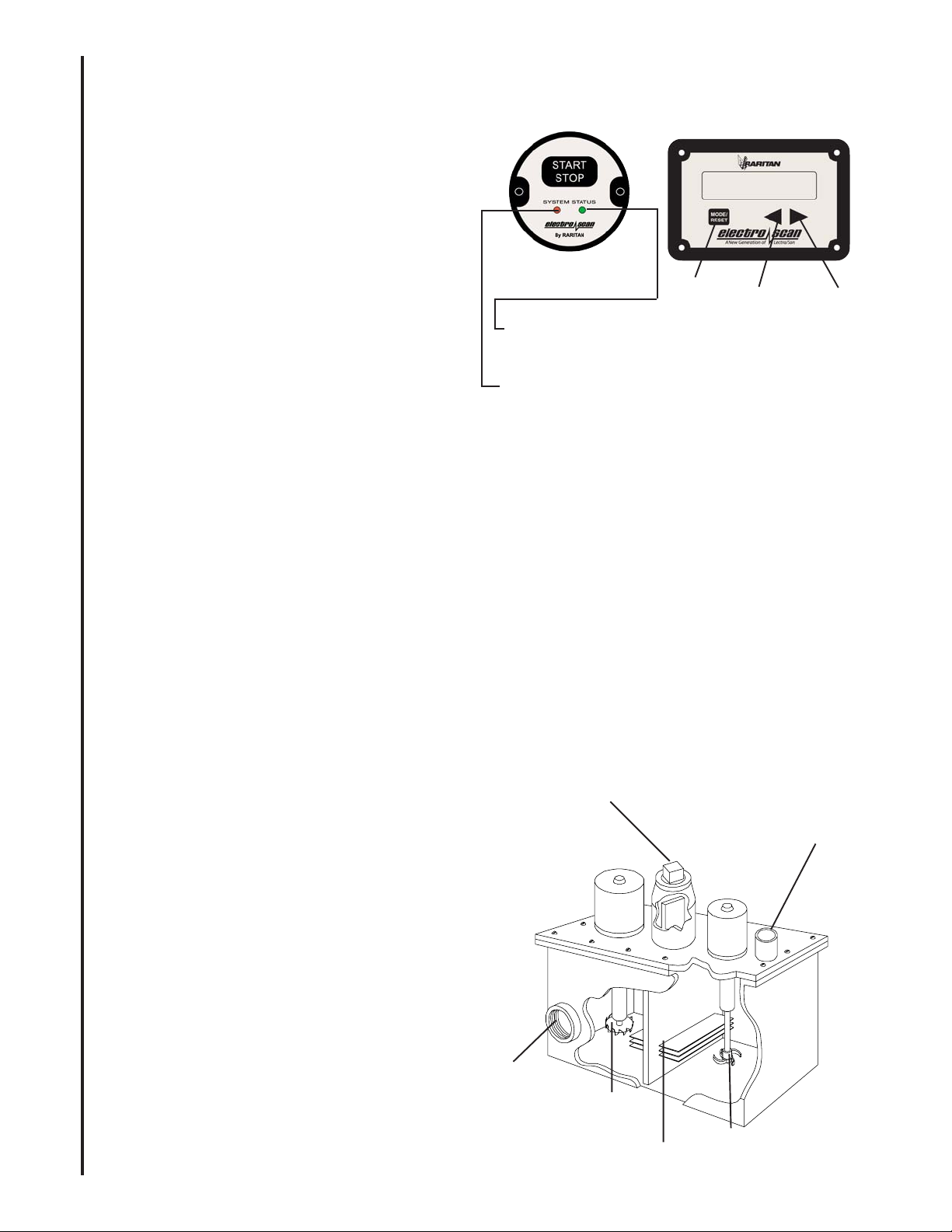
Most operation and troubleshooting information is displayed on the LCD display panel.
Following is the description of display screens and what they mean.
RED LED blinks for warning and is solid for errors
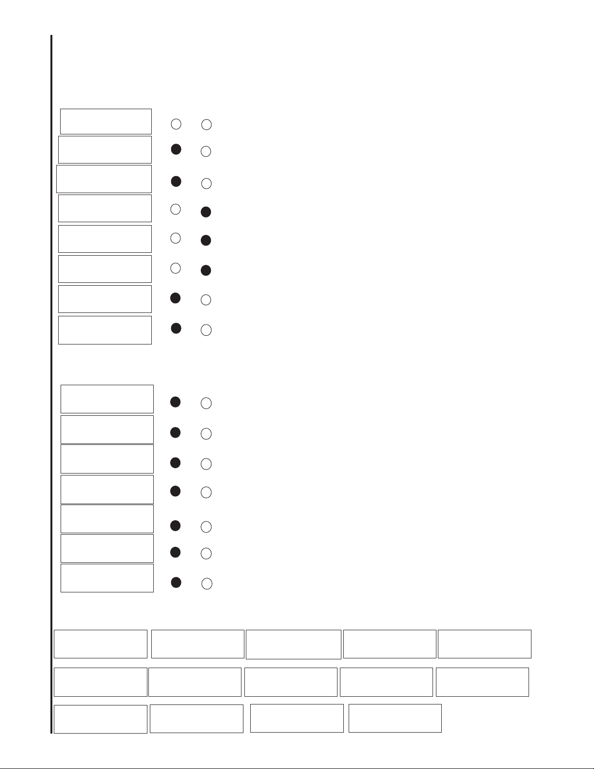
OPERATION
Treatment terminates in ERROR condition for reasons listed below. To clear error condition
after corrective action is taken, hold mode/reset button on display for four seconds.
Following screens can be seen by scrolling up (>) and down (<) keys. These screens display historical summaries of
the data and allow setting of clock and flush timers
TIME 00:00:00TIME 00:00:00
TIME 00:00:00TIME 00:00:00
TIME 00:00:00
DATE: 01/01/00DATE: 01/01/00
DATE: 01/01/00DATE: 01/01/00
DATE: 01/01/00
FLUSHTIME 1FLUSHTIME 1
FLUSHTIME 1FLUSHTIME 1
FLUSHTIME 1
0505
0505
05
FLUSHTIME 2FLUSHTIME 2
FLUSHTIME 2FLUSHTIME 2
FLUSHTIME 2
1010
1010
10
NUMBER OF CYCLESNUMBER OF CYCLES
NUMBER OF CYCLESNUMBER OF CYCLES
NUMBER OF CYCLES
0010000100
0010000100
00100
NUMBER OF RESETSNUMBER OF RESETS
NUMBER OF RESETSNUMBER OF RESETS
NUMBER OF RESETS
0000
0000
00
CYCLE W/O LSTCYCLE W/O LST
CYCLE W/O LSTCYCLE W/O LST
CYCLE W/O LST
000000
000000
000
LOW AMP 14-18LOW AMP 14-18
LOW AMP 14-18LOW AMP 14-18
LOW AMP 14-18
000000
000000
000
LOW AMPS 7-14LOW AMPS 7-14
LOW AMPS 7-14LOW AMPS 7-14
LOW AMPS 7-14
000000
000000
000
LOW AMP SHUT-LOW AMP SHUT-
LOW AMP SHUT-LOW AMP SHUT-
LOW AMP SHUT-
DOWNDOWN
DOWNDOWN
DOWN
000000
000000
000
LOW VOLTS < 90%LOW VOLTS < 90%
LOW VOLTS < 90%LOW VOLTS < 90%
LOW VOLTS < 90%
0505
0505
05
LOW VOLT < 83%LOW VOLT < 83%
LOW VOLT < 83%LOW VOLT < 83%
LOW VOLT < 83%
0101
0101
01
MIN TEMPERATUREMIN TEMPERATURE
MIN TEMPERATUREMIN TEMPERATURE
MIN TEMPERATURE
2020
2020
20
LOW VOLT SHUTDOWNLOW VOLT SHUTDOWN
LOW VOLT SHUTDOWNLOW VOLT SHUTDOWN
LOW VOLT SHUTDOWN
0505
0505
05
MAX TEMPERATUREMAX TEMPERATURE
MAX TEMPERATUREMAX TEMPERATURE
MAX TEMPERATURE
9090
9090
90
Display Panel LEDS Status
Green
Red
Voltage was less that 83% of full voltage during the cycle; check
battery , connections and wire sizes.
*****ERROR*********ERROR****
*****ERROR*********ERROR****
*****ERROR****
LOW VOLTAGELOW VOLTAGE
LOW VOLTAGELOW VOLTAGE
LOW VOLTAGE
*****ERROR**********ERROR*****
*****ERROR**********ERROR*****
*****ERROR*****
LOW ELECTROD AMPLOW ELECTROD AMP
LOW ELECTROD AMPLOW ELECTROD AMP
LOW ELECTROD AMP
*****ERROR**********ERROR*****
*****ERROR**********ERROR*****
*****ERROR*****
MIX MOTOR OVERLDMIX MOTOR OVERLD
MIX MOTOR OVERLDMIX MOTOR OVERLD
MIX MOTOR OVERLD
*****ERROR**********ERROR*****
*****ERROR**********ERROR*****
*****ERROR*****
MaC MOTOR OVERLDMaC MOTOR OVERLD
MaC MOTOR OVERLDMaC MOTOR OVERLD
MaC MOTOR OVERLD
*****ERROR**********ERROR*****
*****ERROR**********ERROR*****
*****ERROR*****
ELECTROD OVERLDELECTROD OVERLD
ELECTROD OVERLDELECTROD OVERLD
ELECTROD OVERLD
*****ERROR**********ERROR*****
*****ERROR**********ERROR*****
*****ERROR*****
POS FUSE BLOWNPOS FUSE BLOWN
POS FUSE BLOWNPOS FUSE BLOWN
POS FUSE BLOWN
Electrode amps were lower than 7 amps, check salt, clean electrode
with acid treatment, check all connections.
Mixer motor amps were high, Check for foreign material in mixer
chamber, seal leaks, motor shorts
Macerator motor amps were high, Check for foreign material in
macerator chamber, seal leaks, and motor shorts
Electrode amps were higher than 28 amps during fresh water
operation, check for excessive salt, shorted electrode, wiring.
Positive/Negative fuse on I/O connection board is blown due to
some external short, check toilet solenoid type, wiring to solenoid.
Solenoid (relay) to toilet must be isolated coil type or Raritan
solenoid.
*****ERROR**********ERROR*****
*****ERROR**********ERROR*****
*****ERROR*****
NEG FUSE BLOWNNEG FUSE BLOWN
NEG FUSE BLOWNNEG FUSE BLOWN
NEG FUSE BLOWN
READY TO FLUSHREADY TO FLUSH
READY TO FLUSHREADY TO FLUSH
READY TO FLUSH
****WARNING********WARNING****
****WARNING********WARNING****
****WARNING****
VOLTAGE LOWVOLTAGE LOW
VOLTAGE LOWVOLTAGE LOW
VOLTAGE LOW
**PRETREATMENT****PRETREATMENT**
**PRETREATMENT****PRETREATMENT**
**PRETREATMENT**
VOLTAGE= 100%VOLTAGE= 100%
VOLTAGE= 100%VOLTAGE= 100%
VOLTAGE= 100%
***TREATMENT******TREATMENT***
***TREATMENT******TREATMENT***
***TREATMENT***
VOLTAGE= 100%VOLTAGE= 100%
VOLTAGE= 100%VOLTAGE= 100%
VOLTAGE= 100%
***TREATMENT******TREATMENT***
***TREATMENT******TREATMENT***
***TREATMENT***
AMPS = 15AMPS = 15
AMPS = 15AMPS = 15
AMPS = 15
****WARNING********WARNING****
****WARNING********WARNING****
****WARNING****
AMP = 10AMP = 10
AMP = 10AMP = 10
AMP = 10
****WARNING*******WARNING***
****WARNING*******WARNING***
****WARNING***
VOLTAGE< 87%VOLTAGE< 87%
VOLTAGE< 87%VOLTAGE< 87%
VOLTAGE< 87%
Previous cycle ended normally Ready for next cycle
Previous cycle completed with low voltage, Ready for next
cycle, low voltage should be corrected
Previous cycle completed with low electrode amps, Ready for
next cycle, low amps should be corrected
Unit is in pretreatment cycle after start, voltage displayed,
Unit goes to treatment cycle after pretreatment for 120 seconds,
voltage and amps are displayed alternately.
During the treatment cycle if electrode amps drop below 14,
Warning is displayed, and cycle is extended up to 240 seconds
During the entire cycle if voltage drops below 89% of full battery
voltage, warning is displayed, cycle continues
****WARNING********WARNING****
****WARNING********WARNING****
****WARNING****
AMPS< 14 AMPS< 14
AMPS< 14 AMPS< 14
AMPS< 14