Rath JANUS SmartView User manual

N56W24720 N. Corporate Circle Sussex, WI 53089
800-451-1460 www.rathmicrotech.com
SmartView Visual
Communication System
Installation & Operations Manual
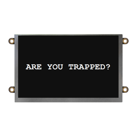
ARE YOU TRAPPED?
RP850001SV
Ver. 12
8/22
WARRANTY
2YEAR

Thank you for purchasing the SmartView Visual Communication System. We are the largest Emergency
Communication Manufacturer in North America and have been in business for over 35 years.
We take great pride in our products, service, and support. Our Emergency Products are of the highest
quality. Our experienced customer support teams are available to remotely assist with site preparation,
installation, and maintenance. It is our sincere hope that your experience with us has and will continue
to surpass your expectations.
Table of Contents
Pre-Installation Requirements . . . . . . . . . . . . . . . . . .
Installation . . . . . . . . . . . . . . . . . . . . . . . . . . . . . . . . . .
Operations and Testing . . . . . . . . . . . . . . . . . . . . . . .
Troubleshooting . . . . . . . . . . . . . . . . . . . . . . . . . . . . .
Controller Layout . . . . . . . . . . . . . . . . . . . . . . . . . . . .
LAN Setup . . . . . . . . . . . . . . . . . . . . . . . . . . . . . . . . . .
Appendix A . . . . . . . . . . . . . . . . . . . . . . . . . . . . . . . . .
Appendix B . . . . . . . . . . . . . . . . . . . . . . . . . . . . . . . . .
Page 3
Page 3
Page 4
Page 4
Page 5
Page 5
Page 7
Page 8
N56W24720 N. Corporate Circle Sussex, WI 53089
800-451-1460 www.rathmicrotech.com

Pre-Installation Requirements
1. Internet Connection:
• Routed internet connection using DHCP
(Network must use private IP address ranges 10.X.X.X or 192.X.X.X or 172.X.X.X)
OR
• Cellular modem with data (available from RATH®)
2. Laptop with a network connection for testing
3. Power Option: 2100-SVE Ethernet Extenders
4. SmartView Controller, SmartView Display, and SmartView Camera
5. YES and NO or DOOR OPEN and DOOR CLOSE buttons
Hardware Mounting
1. Mount the SmartView Controller in the elevator using the provided adapter plate or mounting kit.
2. Mount the Camera in the panel or ceiling of the elevator using the provided hardware. The Camera must be no
more than 15 feet from the Controller.
3. Connect the Camera to the Controller using the provided USB cable.
4. Mount the SmartView Display in the elevator panel. The Display must be no more than 20 feet from the Controller.
Note: Reference Appendix A for Display part numbers and window thickness.
5. Connect the Display to the Controller using the provided HDMI cable.
6. Connect the Display power output (J10) to the SmartView Display power input using the provided cable.
Note: The Controller output power (J10) is only compatible with the SmartView Display.
Note: For use with the CE Elite Pi Display, you must order the Display with the proper software and also the correct
SmartView Controller part number.
7. Connect the button designated for “YES” to the Controller terminal labeled “YES”.
8. Connect the button designated for “NO” to the Controller terminal labeled “NO”.
Note: Use 24AWG wire minimum and 18AWG wire maximum.
Powering Options
1. 2100-SVE Ethernet Extenders
a. Reference diagram on page 5 as a guide.
b. Place the main injector unit and UPS in the machine room or network room.
c. Connect the provided Ethernet cable from a routed network switch to the LAN/PoE port on the main injector.
d. Plug the included power supply into the UPS.
e. Use an existing single pair or run a single pair of wire from the main injector unit to the remote extender unit.
Note: 18AWG wire is recommended.
f. Using the provided RJ45 adapters, wire to pins 1 and 2 and connect the adapters to the Interlink port on the main
injector and Interlink port on the remote extender.
g. Connect the provided Ethernet cable from the PoE Out port on the remote extender to the Ethernet port on the
Controller Board.
Installation
Page 3
N56W24720 N. Corporate Circle Sussex, WI 53089
800-451-1460 www.rathmicrotech.com

Compatible Internet Browsers: Google Chrome, Mozilla Firefox, Microsoft Edge, or Safari
Note: A laptop or computer with a network connection is required for testing.
1. Plug the provided ash drive into your laptop or computer.
2. Open the SmartView link located on the ash drive.
Note: If you have lost the provided ash drive, contact RATH®.
3. Enter one of the IDs associated with your job. A new tab will open automatically.
4. In the new tab you will see the camera feed from the ID.
5. Send a message to the Display by typing into the dialog box and press Enter.
Note: YES and NO responses will be shown adjacent to the dialog box.
6. To test other IDs, close the tab or navigate back to the Rescue Services tab and enter the remaining IDs.
Troubleshooting
Problem Possible Cause & Solutions
The Display is blank: • The display will only power when the system is accessed via the
SmartView Software. Follow the steps in the Operations and
Testing section to verify.
• Verify the polarity from the Display Power Port on the Smartview
Controller to the display. The display is polarity sensitive.
• Verify when accessed by the SmartVIew software, the Display Power Port
on the SmartView controller has 5vdc.
• Verify the HDMI cable from the controller to the display is connected and
fully seeded.
The Software says device is oine or
not connecting:
• Verify the Controller has a routed internet connection and a
minimum of 5MB/S.
• Verify building’s network starts with an IP address of 192, 10, or 172.
• Verify the Ethernet port on the Controller has an amber light and
ashing green light.
• Unplug the ethernet cable from the SmartView controller and plug it into a
laptop and verify web browsing capabilities on the connection.
• In some cases, a rewall will block the SmartView device. An exception
may need to be made for the device in rewall settings. Contact RATH®for
the MAC address of your device if necessary.
• Power cycle controller board by disconnecting ethernet cable for 20
seconds then reconnect.
The software says invalid SmartView
ID:
• Verify that the ID number was entered correctly into the software.
•Verify ID being entered matched ID on Smartview controller.
Finding device’s IP address: • Hold the Yes and No (or Door Open Door Closed if applicable) buttons
simultaneously for 7 seconds.
• The display will show the device’s IP address and server connection.
2100-SVE has no internet in elevator
car:
• Verify the PWR, ETH, and PCL LEDs are illuminated on Main and Remote
Extender.
• Connect remote unit to main unit using a short ethernet cable. Verify PWR
and PLC light are illuminated when connected.
• Verify wires to elevator car are on pins 1 and 2 of RJ-45 terminal
connectors on the Interlink Ports.
Operations and Testing
Page 4

Page 5
Controller Layout
Installation & Wiring Diagrams
RATH Components
2100-SVCB
Camera
(5V, 0.5A)
2100-SVD
Display
(5V, 0.59A)
YES
Machine Room
2100-SVE
(PoE Extender Main)
NO
YES NO
SOM
D PWR PWR
USB Ethernet
RS485
HDMI
RP7700104S
(Power Supply/UPS/Battery)
Elevator Car
2100-SVE
(PoE Extender Remote)
COP
CAT 5E
Outbound
Communication
Source
Single Pair
Wire to pins 1 and 2 of the RJ45 connector.
Extends power and communication up to 1,600 feet.
CAT 5E
When powering via PoE battery backup can be done remotely.
2100-SVC
Controller (PoE Powered)
Notes:
• 2-wire from main Extender to remote Extender
• Ethernet Patch Cable from communication source to main
Ethernet Extender
• Ethernet Patch Cable from remote Ethernet Extender to
SmartView Controller
Machine Room
Elevator Car COP
SmartView Components
Single Pair
Wire to pins 1 and 2 of the RJ45 connector
Extends power and communication up to 1,600 feet
When powering via PoE battery backup can be done remotely.
CAT5E
Ethernet
Patch
Cable 2100-SVE
(PoE Extender Main)
RP7700104S
(Power Supply/UPS/ Battery)
Outbound
Communication
Source
2100-SVE
(PoE Extender Remote)
YES NO
2100-SVD
Display
(5v, 0.59A)
2100-SVCB
Camera
(5v, 0.5A)
Wiring with Ethernet Extenders (2100-SVE) (Must be Supplied by RATH®)
Remote Extender
Main Extender
Battery backup can be done remotely.
Ethernet
Patch
Cable

Wiring Example (Preferred Option for Standard Travel Cable):
RJ45 Adapters Included
with 2100-SVE
• Extender Power: Supplies 1A to the SmartView Controller
• Extender Wiring:
• Extends up to 1,640 feet over single pair of wiring between Extenders (requires
single pair, 18-24ga, shielded or unshielded)
• Ethernet Patch Cable with RJ45 connectors required from network switch and the
SmartView Controller to each Extender
• Main Unit (Injector) has LAN/PoE (internet connection) and Interlink (two wire connection)
• Remote Unit (Extender) has Interlink (two wire connection from main unit) and LAN/PoE
(Ethernet connection to SmartView Controller
Page 6
Wiring to CE Elite Pi Display
Note: For use with the CE Elite Pi
Display, you must order the Display with
the proper software and also the correct
SmartView Controller part number.
SmartView
Camera
YES NO
To SmartView Camera
To PoE+ Network Switch
or
Ethernet Extender
12vdc Supplied from
Switch or Extender
SmartView Controller
(12V, 1A, or 24V 0.5A)
YES NO
InterlinkInterlink

Page 6 Page 7
Appendix A
SmartView Controller Specications:
• Power Requirements: 12v or 24v via Extender
• Curent Draw:
12v Active = 1A
12v Idle = 0.5A
24v Active = 0.5A
24v Idle = 0.25A
• Operating Temperature: 32°F to 158°F (0°C to 70°C)
• Dimensions: 4” H x 7” W x 1.2” D
SmartView Camera Specications (Powered by Controller):
• Power Requirements:
Active = 5v, 0.12A
Idle = 0v, 0A
• Operating Temperature: 32°F to 140°F (0°C to 60°C)
SmartView Display Specications (Powered by Controller):
• Power Requirements:
Active = 5v, 0.59A
Idle = 0v, 0A
• Operating Temperature: -4°F to 158°F (-20°C to 70°C)
• Screen Size: 5 inches
• Part Numbers:
2100-SVD (0.0625” window)
2100-SVDA (0.125” window)
2100-SVDB (0.109” window)
2100-SVDC (0.078” window)
2100-SVDE (0.118” window)

Page 8
SmartView ID Location/Description
10020 Elevator 1
10021 Elevator 2
SmartView ID Location/Description
ID Table:
Appendix B
Example ID Table:
Table of contents
Other Rath Conference System manuals
Popular Conference System manuals by other brands

Logitech
Logitech ConferenceCam Connect quick start guide

Mitel
Mitel Navigator 3300 ICP Technician's handbook

Shure
Shure MXW6W manual

StarTech.com
StarTech.com BEZ4MOD user manual

Polycom
Polycom Vortex EF2280 Programming guide

Alpha Technologies
Alpha Technologies GSM Lift Watch Voice Installation and programming manual